

CarNetix CNX-P1290 Installation And Operation Manual

CarNetix CNX-P1290 V1.0 Installation Manual
CarNetix CNX-P1290 DC-DC Power Supply
(applies to Version 1.0+ hardware)
Installation and Operation Manual
Version 1.0
June 12, 2005
- 1 -

CarNetix CNX-P1290 V1.0 Installation Manual
Table of Contents
1.0 CNX-P1290 Installation Instructions.............................................................................................. 4
1.1 Overview..................................................................................................................................... 4
1.2 Features....................................................................................................................................... 5
1.3 Before You Begin....................................................................................................................... 5
2.0 Installing Your CNX-P1290........................................................................................................... 7
2.1 Identifying the connection points................................................................................................ 7
2.2 Setting the Jumpers..................................................................................................................... 9
JP1 Jumper Settings....................................................................................................................10
JP3 Jumper Settings (+5V Always ON)..................................................................................... 10
JP4 Jumper Settings (Secondary Output Control)...................................................................... 10
2.3 Connecting the Wires................................................................................................................ 12
Power Connection Options:........................................................................................................12
3.0 Option 1: “Power-only” to CarPC through existing case power plug.......................................... 13
3.1 Making the Connections (Option 1): ........................................................................................ 15
Step 1. Run the Power Cable (+12V Battery Cable) .................................................................. 15
Step 2. Run the Ground Wire...................................................................................................... 15
Step 3. Run the Ignition Wire..................................................................................................... 16
Step 4. Connect the output C134 Power Cable........................................................................... 16
Step 5. Connect the LCD Screen (optional)................................................................................ 17
Step 6. Connect auxiliary device(s) (optional). .......................................................................... 17
3.2 Applying power to the system (Option 1): ............................................................................... 18
Step 1. Test your +12V battery cable. ........................................................................................ 18
Step 2. Apply power to the CNX-P1290 .................................................................................... 18
Step 3. Applying Power to your CarPC and Screen ................................................................... 19
Step 4. Turning off your system. ................................................................................................ 20
4.0 Option 2: Power and SSC connection to case using existing case power plug ............................ 21
4.1 Making the Connections (Options 2):....................................................................................... 23
Step 1. Run the Power Cable (+12V Battery Cable) .................................................................. 23
Step 2. Run the Ground Wire...................................................................................................... 23
Step 3. Run the Ignition Wire..................................................................................................... 23
Step 4. Connect the output C134 Power Cable........................................................................... 23
Step 5. Connect the LCD Screen (optional)................................................................................ 23
Step 6. Connect auxiliary devices (s) (optional)......................................................................... 23
Step 7. Connect the ACPI/PWRON to the motherboard............................................................23
4.2 Applying power to the system (Option 2): ............................................................................... 26
Step 1. Test your +12V battery cable. ........................................................................................ 26
Step 2. Apply power to the CNX-P1290 .................................................................................... 26
Step 3. Applying Power to your CarPC and Screen ................................................................... 26
Step 4. Turning off your system. ................................................................................................ 26
5.0 Option 3: Power and SSC connection to case using internal power and SSC connections.......... 28
5.1 Making the Connections (Option 3): ........................................................................................ 31
Steps 1 through 3 are identical to Option 2 above...................................................................... 31
Step 4. Connect the output Case Power Cable............................................................................ 31
Steps 5 & 6 are identical to Option 2 above. .............................................................................. 32
5.2 Applying power to the system (Option 3): ............................................................................... 33
- 2 -

CarNetix CNX-P1290 V1.0 Installation Manual
6.0 Using the Pulse Start Feature........................................................................................................ 34
6.1 Pulse Start Connections ............................................................................................................ 34
6.2 Pulse Start Operation ................................................................................................................ 34
6.2.1 What is a pulse?................................................................................................................. 34
6.2.2 Starting the PSU with a pulse ............................................................................................ 34
6.2.3 Stopping the PSU with a pulse........................................................................................... 35
6.2.4 Prolonging the Shutdown Delay State...............................................................................35
6.2.5 Shutting down the PSU with double pulses....................................................................... 35
6.2.6 Ignition Override................................................................................................................ 35
7.0 CNX-P1290 Startup/Shutdown Controller................................................................................... 36
7.1 Hibernate/Standby Operation.................................................................................................... 36
7.2 SSC Operation States................................................................................................................ 36
7.2.1 Idle State ............................................................................................................................ 36
7.2.2 RunDelay State .................................................................................................................. 36
7.2.3 Bootup Lockout State ........................................................................................................ 37
7.2.4 Run State............................................................................................................................ 37
7.2.5 Shutdown Delay State........................................................................................................ 37
7.2.6 Shutdown Sequence State.................................................................................................. 37
7.2.7 Forced Shutdown State...................................................................................................... 38
7.3 Fault Indicator LEDS................................................................................................................ 38
- 3 -
CarNetix CNX-P1290 V1.0 Installation Manual
1.0 CNX-P1290 Installation Instructions
NOTE: This manual and feature set apply to Rev 1.0 and above of the printed circuit board (PCB).
The PCB revision number is printed on the top of the PCB in white lettering. Please make sure you
are using the correct manual for the correct product revision.
1.1 Overview
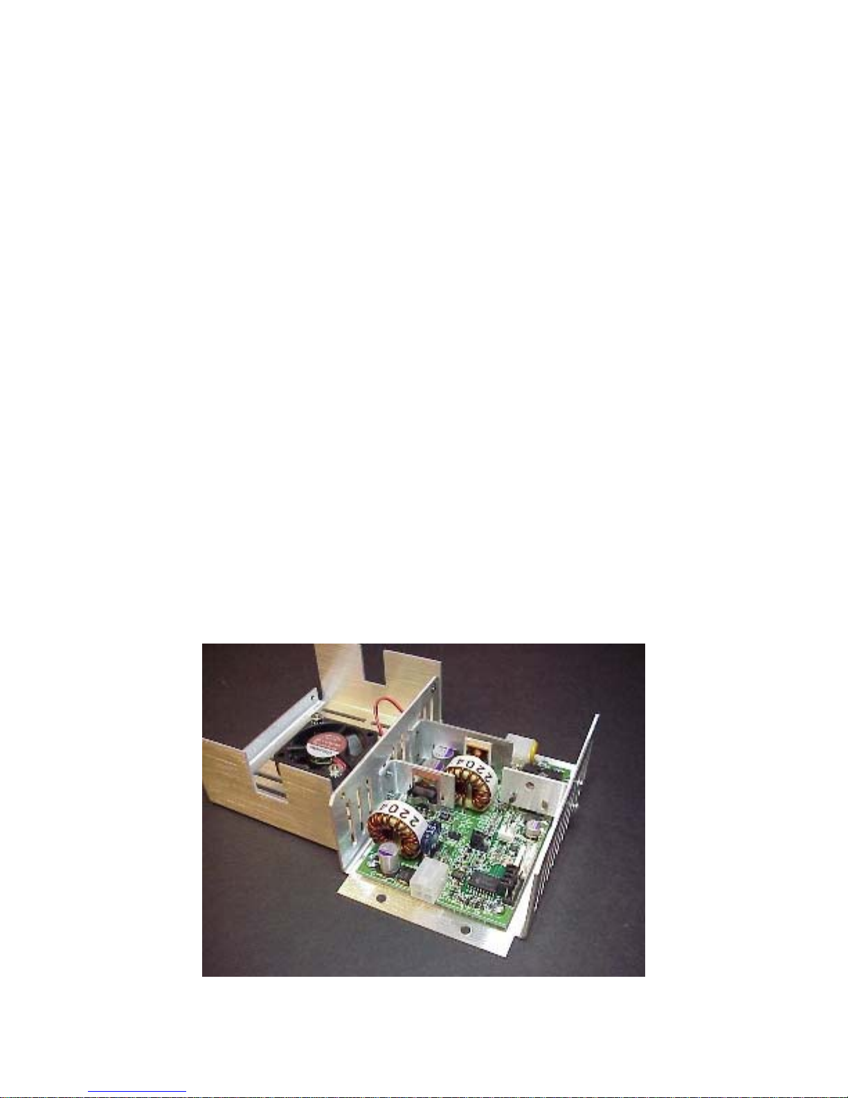
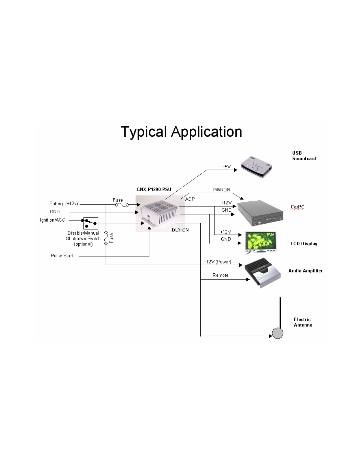
The CNX-P1290 is a 90 watt intelligent DC-DC power regulator designed to provide safe, reliable
power to today's newest CarPCs......including Travla & Morex cases, as well as many of the
Sumicom and Xenarc PC systems.
The P1290 provides two outputs. The primary output is +12V and can provide up to 6.3 amps (75
Watts). The secondary output is +5V to power USB devices (such as the Audigy 2NX sound USB
sound card) with up to 3 amps (15 Watts). The P1290 can accept battery input as low as 7 volts
under full load (90 watts) during cranking while providing a well-regulated output so that your
CarPC does not crash.
The P1290 now includes an internal relay to control the ACPI interface of the Sumicom and Xenarc
PCs. No more soldering an external relay between the P1290 and the PC!
The P1290 includes all of the sophisticated features of its predecessors (P1260 and P1280) such as
Startup/Shutdown controller, Pulse Start (remotely start the P1290 with door locks, car alarm, or
wireless device), and DelayON (prevents speaker "thump" during booting). The P1290 fully and
safely supports "Standby" mode and will automatically shut itself down (by detecting excess current
drain) if the CarPC fails to properly go into Standby mode.
- 4 -

CarNetix CNX-P1290 V1.0 Installation Manual
1.2 Features
• 90 Watt Dual Output Regulator
• Main output of +12V @ 6.3 Amps
• Secondary output of +5V @ 3 Amps
• Survives Engine Cranking under full load over entire temperature range
• Includes sophisticated Startup/Shutdown Controller
• Compatible with many of the Sumicom and Xenarc PC Systems.
• INCLUDES INTERNAL ACPI RELAY FOR SUMICOM AND XENARC PCs
• Includes sturdy aluminum chassis with variable speed fan suitable for car
environment
• Field upgradeable flash microprocessor
• Low battery monitor prevents drained battery, even during Standby/Sleep
• "Anti Thump" delayed remote control for audio amplifiers
• Remote "Pulse Start" from wireless device or car alarm/remote start system
• Over current protection on both outputs with graceful forced shutdown of main
output
• Powers both your CarPC AND your screen or USB devices
• Compatible with many of the Travla & Morex cases
• Full, safe support for Windows Standby mode including auto shutdown if PC fails to
shutdown
• Over voltage surge suppression on battery input for protection of harsh automotive
environment
• User replaceable fuse on battery input to protect your car from internal short circuits
• Very compact design measuring just 4.6" x 3.25" x 1.75" (L x W x H) or 117mm x
83mm x 45mm.
1.3 Before You Begin
Before you begin the installation, make sure you take the time to read through these instructions. The
CNX-P1290 is a sophisticated, microprocessor-based device. If the proper installation steps are not
followed, various types of problems could occur ranging from nuisance resets of your CarPC, to
“Car-B-Que” (ie flames). Please read these instructions carefully and contact us either in our Support
Forum (
or problems.
It is assumed that you have a basic to advanced understanding of electronics. It would be helpful,
and is highly recommended (especially if you plan to get much further involved in CarPCs) that you
purchase, as a minimum, a simple VOM (volt-ohm meter) or DMM (Digital Multi-Meter). These
devices are inexpensive (starting around $20) and will save you and me a great deal of time. They
can be purchase over the web or at your local retail electronics store (Radio Shack, Home Depot,
some hardware stores, some auto parts stores).
Whether you plan to use the on-board Startup/Shutdown Controller (SSC) or not, please read the
section describing its operation first, before attempting to install the CNX-P1290. The SSC will
affect the power turn-on and turn-off operation whether you use its features or not.
- 5 -
www.carnetix.com/forum) or via email (support@carnetix.com) if you have any questions
CarNetix CNX-P1290 V1.0 Installation Manual
- 6 -

CarNetix CNX-P1290 V1.0 Installation Manual
2.0 Installing Your CNX-P1290
Installing the CNX-P1290 involves 4 basic steps:
• Identifying the connection points:
• Setting the Jumpers:
• Connecting the wires:
• Turning on the system:
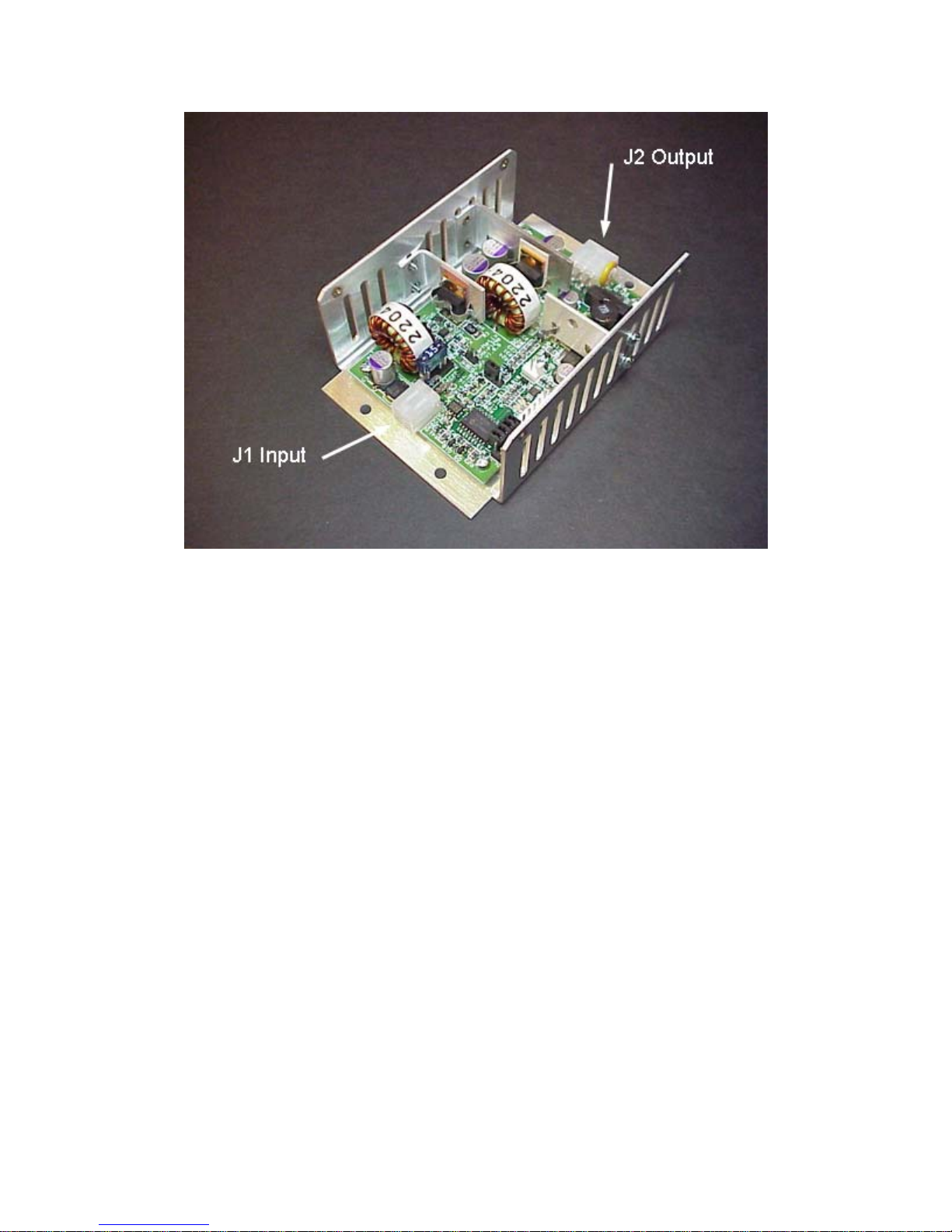
2.1 Identifying the connection points
Figure 3 shows the location of J1 (Input connector) and J2 (Output connector). Note that J1 has 4
pins, while J2 has 6 pins. The pin connections/functions are as follows:
Pin Wire Color Function
1 Blue Pulse Start Input (See Section 6)
2 Yellow Ingition/ACC input
3 Black Ground
4 Red +12V Battery Input
Figure 1 J1 Input Connector Pinouts
Pin Wire Color Function
1 White +5V Output
2 Black ACPI Return
3 Green ACPI/PWRON
4 Red +12V Output
5 Black Ground
6 Blue DLYON
Figure 2 J2 Output Connector Pinouts
- 7 -
CarNetix CNX-P1290 V1.0 Installation Manual
Figure 3 J1 and J2 Location
- 8 -
CarNetix CNX-P1290 V1.0 Installation Manual
2.2 Setting the Jumpers
Note: Before adjusting the jumpers from their default positions, read the section on the SSC at the
end of this document.
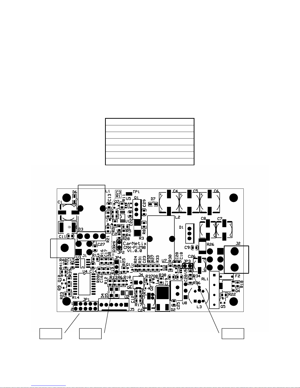
There are 3 jumpers on the CNX-P1290. Below is a picture of their location on the board. You will
need to remove the 4 screws that hold the lid, remove the lid, and disconnect the fan wire to get
access the jumpers. Once you have selected your desired jumper positions, replace the fan wire (note
polarity of connector), replace the lid, and replace the 4 lid screws. Be careful not to let the fan wire
touch the blades of the fan as your replace the lid.
Jumper Functions
JP1 Pulse Start Input
Shutdown Delay Time
Hibernate/Standby
DelayOn Option
JP3 +5V Always On
JP4 Secondary Output Control
- 9 -
Figure 4 Jumper Location
JP-3 JP-4 JP-1

CarNetix CNX-P1290 V1.0 Installation Manual
JP1 Jumper Settings
Below is a table with the jumper selectable options for JP1. To move a jumper from its factory
default position, use a pair of tweezers or needle nose pliers. Be careful to place the jumper in the
correct position or erratic behavior could result. Double-check your settings before replacing the lid.
JP1 Jumper Pin Assignments
Pins
1-2 3-4 5-6 7-8 9-10
Function
Open
(default)
Jumpered
Pulse Start
Input
Connect to
external
contact
closure
Connect to
external
contact
closure
Shutdown
Delay
Time
6 Seconds Hibernate Not Used
1 minutes Standby Not Used
Hibernate/
Standby
Not Used
DelayOn
Option
DLYON
follows IGN
DLYON
follows PSU
Table 1 JP1 Settings
Once the jumper selections have been made you may begin installing the wiring to connect the
CNX-P1290 to your car’s electrical system, and to your CarPC.
JP3 Jumper Settings (+5V Always ON)
For those users who want to keep +5V USB devices powered even when the CarPC is OFF or in
Standby, you can jumper Pin1 to Pin 2 on JP3. This will keep the +5V regulator ON at all times,
even if the P1290 is OFF. Use caution when using this jumper position since it may cause your
battery to drain quickly.
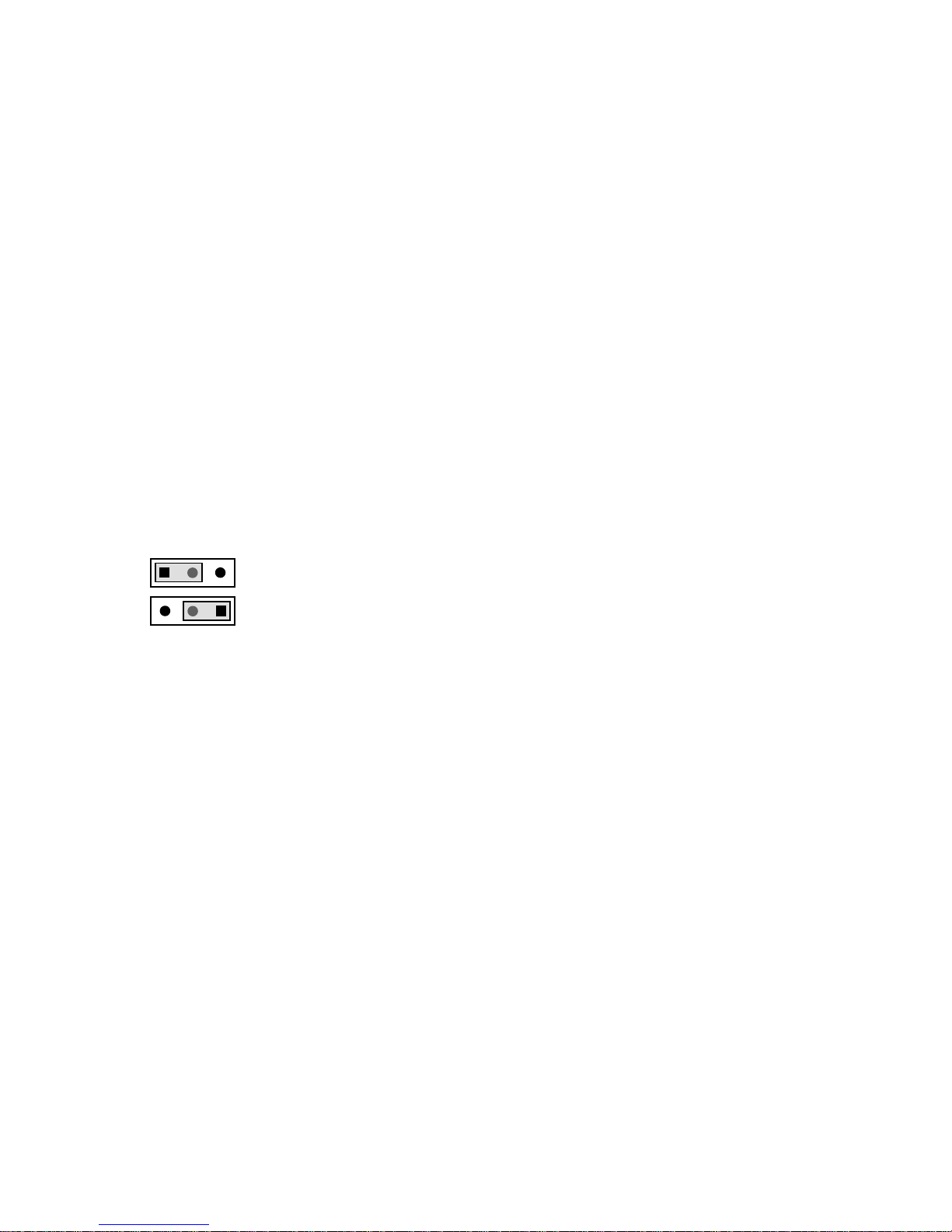
JP4 Jumper Settings (Secondary Output Control)
The JP4 jumper gives you the flexibility to use the Secondary Output in different ways depending
upon your CarPC system configuration. The Secondary Output can be turned on or off based on two
different control signals: 1) DLYON or, 2) the signal that controls the Primary Output (PRI OUT).
- 10 -
CarNetix CNX-P1290 V1.0 Installation Manual
• DLYON
Jumpering DLYON will turn your Secondary Output ON or OFF with the DLYON signal. This
means that your Secondary Output will come on 3 seconds after your Primary Output comes ON,
and will go off when you turn your ignition switch OFF.
• PRI OUT
Jumpering PRI OUT will make the Secondary Output follow the control used to turn ON and OFF
the Primary Output. Thus, when the Primary Output is ON, the Secondary Output will also be ON. If
the Primary Output is OFF, the Secondary Output will be OFF.
This setting is affected by the jumper setting of the Shutdown Delay jumper on JP1. If you have set
the Shutdown Delay jumper to the default position (6 seconds), both the Primary and Secondary
Outputs will be turned OFF 6 seconds after the Ignition is turned OFF. If you have set the Shutdown
Delay jumper for 1 minutes, both the Primary and Secondary Outputs will remain ON for 1 minutes
after the Ignition is turned off. This setting is useful for keeping certain USB devices powered during
the Shutdown Delay time. For example, if you use the Secondary Output to power your USB sound
card and you want to keep your sound card powered during the Shutdown Delay time (1minutes),
then set the jumper JP4 for PRI OUT. Another application might be to keep a USB WiFi card
powered during Shutdown Delay for file transfer.
Follows DLYON
Follows PRI OUT
- 11 -

CarNetix CNX-P1290 V1.0 Installation Manual
2.3 Connecting the Wires
The CarNetix CNX-P1290 can be installed in a variety of ways, depending upon the system
requirements. The primary target CarPC for the CNX-P1290 are the Casetronic (Travla) C13X series
and the Cubid 26XX and 36XX series, with an internal Morex 60 Watt DC-DC PSU. The Morex
PSU requires an input of +12V +/-5%, which is provided by Primary Output of the CNX-P1290.
The +5V Secondary Output is typically used to provide power to USB devices.
In addition, the CNX-P1290 includes an on-board Startup/Shutdown Controller (SSC) which may be
used if desired, but which is NOT required if all you want is power for your CarPC. The CNXP1290 also provides a delayed control signal to turn on auxiliary devices such as audio amplifiers,
after power has been applied to your CarPC. This helps prevent an audible “thump” in your speakers
when power is applied to both the CarPC and the audio amp at the same time.
Three different installation configurations are presented here. They are specific to the C134, but the
same techniques apply to other CarPC cases. If you have questions regarding a different type of
CarPC that is not addressed here, please visit our Support Forum and ask the specific question there.
Power Connection Options:
1) Option 1: Power-only to CarPC through existing case power plug.
• Does not use the SSC (Startup/Shutdown Controller) and does not require opening the
case
2) Option 2: Power and SSC connection using existing case power plug.
• Requires opening the case to attach SSC ACPI control to motherboard
• Uses existing case power plug
3) Option 3: Power and SSC connection using internal power connector and SSC connection.
• Requires opening case to attach SSC
• Requires removal of existing case power plug to connect to PSU
Note: Similar to the installation of any aftermarket electronic device (i.e. audio power
amplifier), battery power (+12V) cables, grounding cables, and fuses are NOT supplied as
part of the CNX-P1290 kit. These installation cable kits can be purchased from a variety of
on-line and retail locations such as auto-parts stores, Wal-Mart, and electronics outlets. The
CNX-P1290 does provide “pigtail” connectors for connecting to the CNX-P1290 (see
Identifying the Connecting Points above).
- 12 -

CarNetix CNX-P1290 V1.0 Installation Manual
3.0 Option 1: “Power-only” to CarPC through existing case
power plug
This is the simplest connection configuration, and also the least functional. It merely provides
regulated +12V to the CarPC and does not take advantage of the on-board SSC of the CNX-P1290.
However, for the beginner (or faint of heart), it may be a good starting point.
To install the CNX-P1290 in this configuration you will run 3 wires into the unit (+12v battery,
Ground, and Ignition), and one power cable consisting of two wires (+12VDC, Ground) out of the
unit to the C134. This installation requires the optional CNX-CA-134 wiring kit. Optionally, you can
connect your LCD display screen (i.e. Lilliput or Xenarc) and one or more auxiliary devices such as
your head-unit, audio amplifier, and electric antenna. Please note that these auxiliary devices DO
NOT get their supply power from the CNX-P1290. They only get a “remote turn-on” signal form the
CNX-P1290. This signal, called DLYON (delayed on) provides an UN-REGULATED +12VDC
control signal to these units. The capacity of this line is 500mA maximum and is current limited with
an internal, self-resetting fuse.
Below is a detailed connection diagram for the C134 case and Morex PSU.
- 13 -
 Loading...