

Page 1
RECEIVING, HANDLING AND STORAGE
1. Handle the fan with care. Avoid severe jarring or dropping of the unit.
2. Carefully inspect the unit for damage upon delivery. If the unit has been damaged in transit it is the responsibility of
the recipient to make all claims against the carrier.
3. Provide adequate, protected storage prior to installation. Upon unpacking, inspect the unit for any damage that
may have occurred in transit and check for loose or missing parts.
INSTALLATION
1. Upon unpacking, inspect the unit for any damage that may have occurred in transit. Check also for loose or
missing parts.
2. This fan is designed and manufactured for either supply or exhaust application. Fans cannot be reversed in the
field to provide airflow other than as designed.
3. CAUTION! This fan contains rotating parts and requires electrical service. Appropriate safety precautions should
be taken during installation, operation and maintenance.
4. WARNING! Do not install or operate this fan in environment or atmosphere where combustible or flammable
materials, gasses or fumes are present, unless it has specifically designed and manufactured for use in that
environment. Explosion or Fire could result!
5. This ventilator is designed to be mounted in a wall or other building opening.
6. A damper, if used, should be securely mounted within the ductwork or opening in a manner which allows free and
unobstructed operation. Allow a minimum of 8” of clearance from between the fan and damper.
7. CAUTION! All electrical work must be done in accordance with local and/or national electrical code as applicable.
If you are unfamiliar with methods of installing electrical wiring, secure the services of a qualified electrician.
8. WARNING! This product must be grounded.
9. DANGER! Make sure power is turned off and locked in the OFF position at the service entrance before installing,
wiring or servicing fan.
10. CAUTION! Before wiring the motor, check the supply voltage against the motor nameplate voltage. High or low
voltage can damage the motor and void the motor warranty.
11. WARNING! Be sure to keep all wiring clear of rotating or moving parts.
12. WARNING! Before starting the fan, turn the propeller to assure it rotates freely. If needed, adjust the
propeller/shaft/bearing/motor position as required to achieve necessary clearances.
13. WARNING! Check all set screws and keys. Tighten as necessary prior to fan startup.
14. Anchor the fan securely to the opening. Use a minimum of four lag bolts or other suitable fasteners.
OPERATION
1. CAUTION! Assure the fan inlet/ductwork/exhaust openings are clean and free of obstructions.
2. WARNING! This fan contains rotating parts. Appropriate safety precautions should be taken during operation.
3. Operate under power and check for correct rotation direction.
4. CAUTION! Incorrect rotation can damage the fan motor.
Form 1416-B, Page 1
CARNES COMPANY, 448 S. Main St., P. O. Box 930040, Verona, WI. 53593-0040 Phone: 608/845-6411 Fax: 608/845-6504 [email protected] www.carnes.com
INSTALLATION, OPERATING AND MAINTENANCE INSTRUCTIONS
DIRECT DRIVE PROPELLER WALL FANS
MODELS LYDK (Exhaust) and LZDK (Supply)
CAUTION!
DO NOT INSTALL, USE OR OPERATE THIS EQUIPMENT UNTIL THIS MANUAL HAD BEEN READ
AND UNDERSTOOD. READ AND SAVE THESE SHEETS FOR FUTURE USE.
FORM 1416-B
Page 2
MAINTENANCE
1. DANGER! Before performing any maintenance on the fan, be sure power is turned off and locked in the OFF
position at the service entrance before servicing the fan.
2. Ventilators should be carefully checked at least once a year. For critical or rugged applications, a routine check
every two or three months is suggested.
3. All motors supplied with CARNES ventilators carry a one year warranty from date of shipment. For repairs within
the warranty period, the motor must be taken to the motor manufacturer’s authorized service dealer. Contact your
CARNES representative for additional warranty details.
4. A periodic motor check should consist of spinning the motor shaft with the power off to be sure the motor turns
freely.
5. The propeller should not require maintenance except for removing foreign materials that may accumulate on the
blades. The balance weights should not be disturbed. If a propeller has to be removed from the shaft, do not apply
force that will damage the bearing or warp the propeller. Use a wheel puller.
2
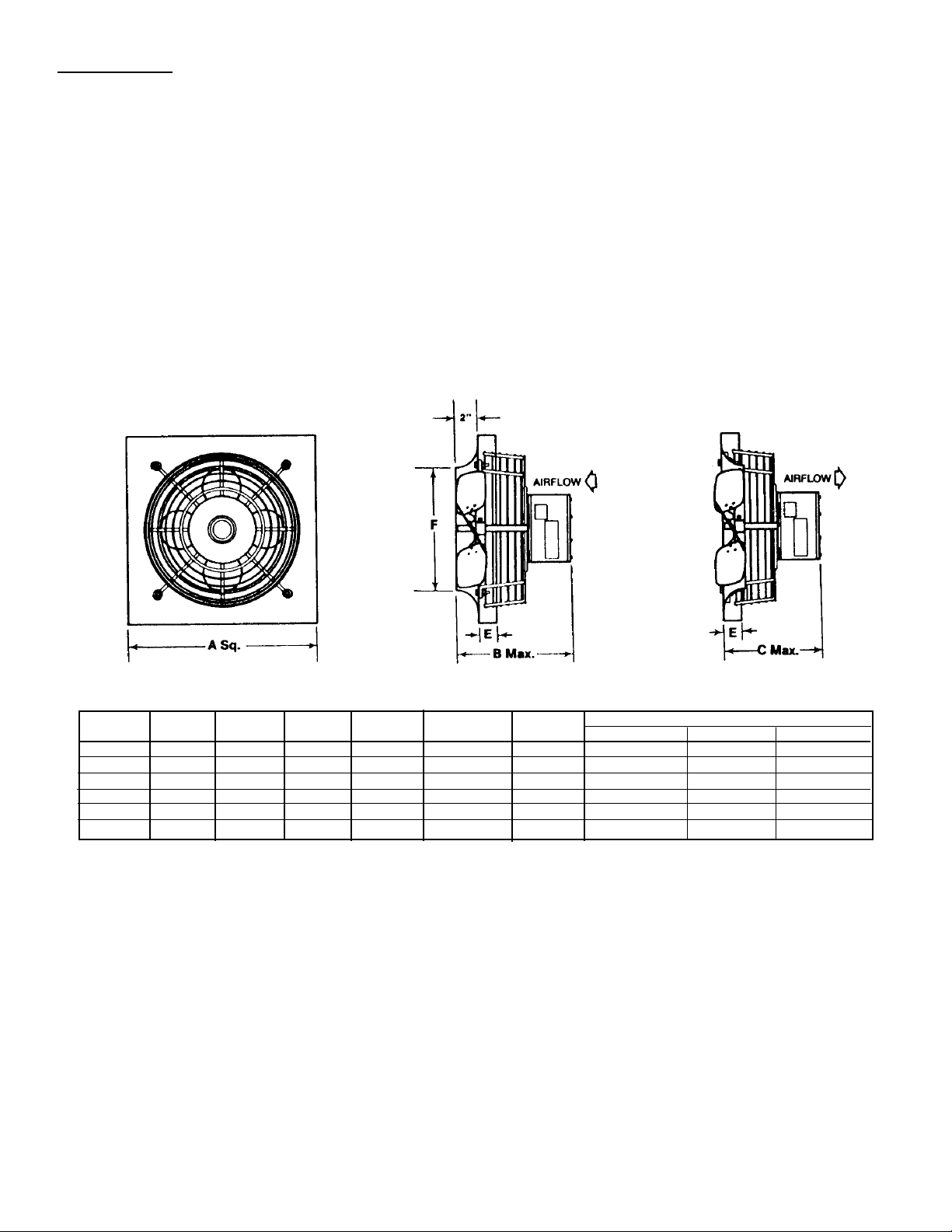
DIMENSIONS (Listed In Inches)
Fan A Weight Material Thickness
Size SQ. B C E F (LBS.) Panel/Venturi Wire Guard MotorSupport
9-10 16 11 10 1-1/2 10-1/4 20 16 ga. 12 ga. 1/4 in.
11-12 16 11 10 1-1/2 12-1/4 20 16 ga. 12 ga. 1/4 in.
13 20 12 11 1-1/2 14-1/4 25 16 ga. 12 ga. 1/4 in.
15-16 20 13 12 1-1/2 16-1/4 30 16 ga. 12 ga. 1/4 in.
17-18 24 13 12 1-1/2 18-1/4 35 16 ga. 12 ga. 1/4 in.
19-21 24 13 12 1-1/2 20-1/4 40 16 ga. 12 ga. 1/4 in.
MODEL LYDK
EXHAUST
MODEL LZDK
SUPPLY
DIRECT DRIVE WITH INTEGRAL MOTORSIDE GUARD - MEETS OSHA REQUIREMENTS.
ONE PIECE FAN PANEL/VENTURI WITH PREPUNCHED MOUNTING HOLES.
PANEL MATERIAL - GALVANEALED STEEL WITH ELECTROCOAT BAKED ENAMEL (GREY).
OSHA MOTORSIDE GUARD - WELDED STEEL WIRE, FINISH TO MATCH PANEL.
MOTORS - 115/1/60 ODP SPEED CONTROLABLE - PERMANENT SPLIT CAPACITOR.
NEOPRENE VIBRATION MOUNTS BETWEEN MOTOR MOUNTS AND FAN PANEL.
PROPELLER STATICALLY AND DYNAMICALLY BALANCED.
ALUMINUM 3 OR 4 BLADE PROPELLER WITH STEEL HUB AND SET SCREWS.
MOTORS FACTORY WIRED TO CONDUIT/WIRING BOX.
PANEL FLANGES TURNED TO THE MOTORSIDE (BOTH EXHAUST & SUPPLY) FOR EASY MOUNTING.
CONDUIT KNOCKOUT IN FAN PANEL FOR FIELD WIRING MOTORIZED DAMPER.
FACTORY RUN-TEST FOR DEPENDABLE OPERATION.
STANDARD SPECIFICATIONS AND CONSTRUCTION
Page 3
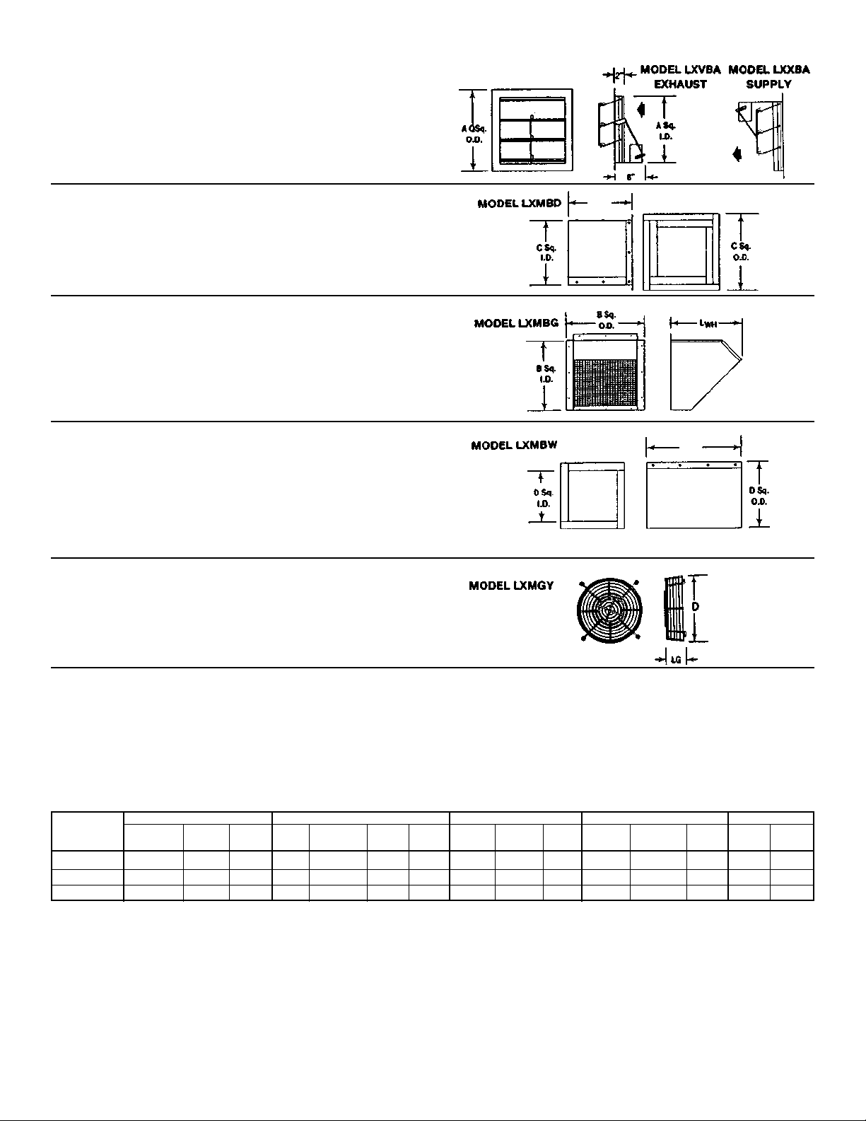
BACKDRAFT SHUTTER - Flanged frame style. .063
alum. frame and 24 ga. alum. blades with blade linkage.
Max. Velocity = 2500 FPM. Blade seals are felt and
polyurethane at sill. Mounts easily to wall collar or wall
box. Flanged frames recess into wall opening.
Motor Kit: 115-230/1/60 POSC (0.26 amps) Ships loose.
WALL COLLAR - 18 ga. galvanealed steel with
prepunched mounting holes for easy attachment of fan
and accessories.
Aluminum construction.
Painted finish (Baked enamel, acid resistant coating,
air dry heresite, other)
WEATHER HOOD - 18 ga. galvanealed steel with prepunched mounting holes. Attaches to wall collar or wall
box. Inlet birdscreen is 1/2” x .041 galvanized wire mesh.
Aluminum construction.
Painted finish (Baked enamel, acid resistant coating, air
dry heresite, other)
WALL BOX - Extends outside building. 18 ga. galvanealed steel - prepunched for attachment to fan and
accessories.
Aluminum construction.
Painted finish (Baked enamel, acid resistant coating, air
dry heresite, other)
Mounting angle flanges - pre-cut galvanized (field drilled)
for attachment of wall box to wall.
PROPELLER SIDE GUARD - (Motorside guard is
standard) welded 12 ga. steel wire meets OSHA
requirements. Use when propeller side is exposed.
Baked enamel finish. Bolts directly to fan panel.
Disconnect switch with junction box and cover (loose) - Model JXLA (NEMA 1), Model JXFA (NEMA 3R).
Electronic speed control with junction box and cover (loose) - Model JXUA (3A), JXVA (6A), or JXWA (10A).
UL 705/CUL 710 listing for electrical safety and reliability.
Factory assembled package - fan and accessories. Electrical accessories ship loose.
Birdscreen/wire guard (1/2” x .041 galv.) - Model LXMBE for wall collar and LXMBX for wall box.
Not to be used with backdraft damper.
DIMENSIONS (Inches) AND WEIGHTS
Shutter Weather Hood Wall Collar Wall Box Prop Guard
Fan A Sq. A Sq. Wt. B Sq. B Sq. Wt. C Sq. C Sq. Wt. D Sq. D Sq. Wt. Wt.
Size OD ID Lbs. L
WH OD ID Lbs. OD ID Lbs. OD ID Lbs. D Lbs.
9-12 15-1/4 12-1/4 2 14 15-1/2 14 11 19-1/4 16-1/4 16 16-1/4 13-1/4 20 15 2
13,15-16 19-1/4 16-1/3 4 18 19-1/2 18 15 23-1/4 20-1/4 19 20-1/4 17-1/4 24 19 3
17-21 23-1/4 20-1/4 6 20 23-1/2 22 20 27-1/4 24-1/4 23 24-1/4 21-1/4 29 23 4
24”
16”
3
Page 4
COMPANY
448 South Main Street
P. O. Box 930040
Verona, WI
53593-0040
Phone: 608/845-6411
Fax: 608/845-6504
E Mail: [email protected]
www.carnes.com
4
 Loading...