

Page 1
Volume Control Dampers
www.carnes.com F-75
Volume Control Dampers
Volume Control Dampers - Galvanized
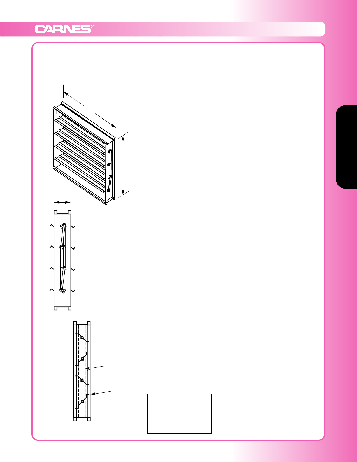
Model: FDNB Opposed Blade Channel Frame, FDQB Parallel Blade Channel Frame,
FDPB Opposed Blade Flanged Frame, FDRB Parallel Blade Flanged Frame
Model FDNB and FDQB
t Standard Specifications
Frame: roll formed galvanized steel
Blades: 4” - 7” wide, 16 gauge galvanized steel
Bearings: nylon
Linkage: concealed in frame
Axles: 3/8” square plated steel
Control Shaft: Ø1/2” x 4-1/2” long shaft supplied with all single
section dampers for field mounted actuators. Factory-installed
jackshaft supplied with all multiple section dampers.
Maximum Panel Size: 48”w x 60”h (single section)
Maximum multi-section: unlimited
Minimum Panel Size: 6”w x 6”h
9”h and under - single blade
Options
• Vinyl Blade Seals
• Compression Jamb Seals (stainless steel)
• Header Plates (end flange)
• Hand Quadrant
• Factory Installed Actuators
• Position Switch
• Face and By-pass Damper
• Chain Operator
• Single Flange
• Double Flange
• Bolt Holes in Flange
• Stainless Steel Bushings
• Heresite Coated (air dry)
• Epoxy Coated (powder coated)
• Stand Off Bracket, 2”
W
H
5”
Optional
Stainless steel
jamb seals
Vinyl blade seals
12” wide -3500 FPM
24” -2800
36” -2300
48” -2100
FPM Table
Page 2
Volume Control Dampers
Volume Control Dampers
F-76 www.carnes.com
Galvanized Volume Control Dampers
Model: FDNB and FDQB
Ratings shown are based on tests made in accordance with AMCA standard 500.
Damper
Width x Height
1 in. w.g. Class 4 in. w.g. Class 8 in. w.g. Class
*Torque
(per sq. ft.)
36” x 36” Class III Class III Class III 5.55 lbs-in
Imperial Units (Forward Flow)
*Torque applied to hold damper in closed position.
Damper
Width x Height
1 in. w.g. Class 4 in. w.g. Class 8 in. w.g. Class
*Torque
(per sq. ft.)
36” x 36” Class III Class III Class III 5.55 lbs-in
Imperial Units (Back Flow)
*Torque applied to hold damper in closed position.
Damper
Width x Height
(mm)
250 Pa Class 1 kPa Class 2 kPa Class *Torque
915 x 915 Class III Class III Class III 6,394 grams-cm
Standard International Units (Forward Flow)
*Torque applied to hold damper in closed position.
Damper
Width x Height
(mm)
250 Pa Class 1 kPa Class 2 kPa Class *Torque
915 x 915 Class III Class III Class III 6,394 grams-cm
Standard International Units (Back Flow)
*Torque applied to hold damper in closed position.
Air leakage is based on operation
between 50°F to 104°F. All data
corrected to represent air density
of 0.075 lbs/ft.
3
Air leakage is based on operation
between 10°C to 40°C. All data
corrected to represent air density
of 1.201 kg/m.
3
PL-1
PL-7 PL-X
PL-Y
M
AIRFLOW
AIRFLOW
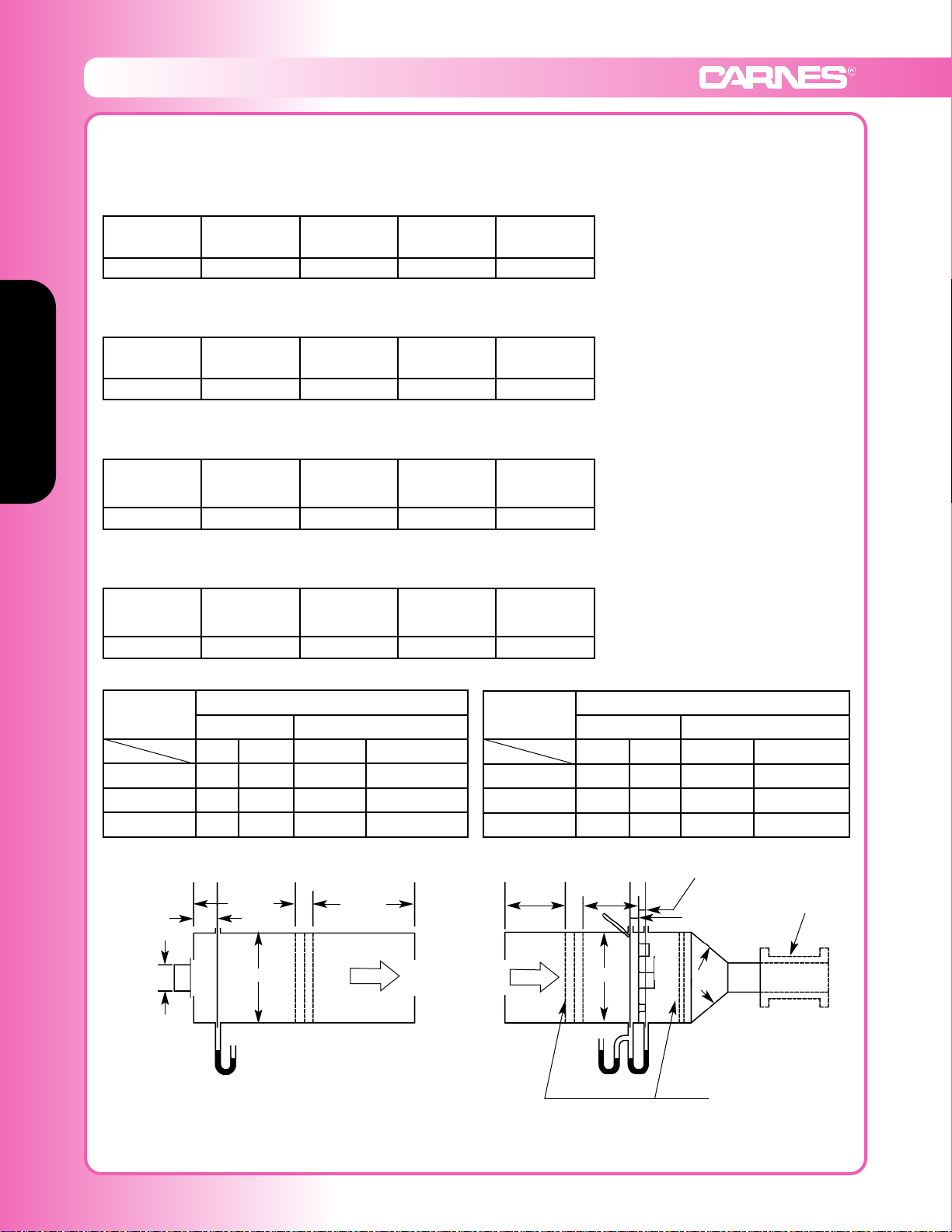
Figure 5.4 - Test Device Setup with Outlet Chamber
Note: For pressure drop testing an outlet
chamber shall have a cross sectional
area at least fifteen times the free
area of the device being tested.
P
s7
W + H
75mm ± 6mm
(3 in. ± .025 in.)
Device
being
tested
M/2 min.
M/2 min.
Figure 6.3 - Airflow Rate Measurement Setup -
Multiple Nozzle Chamber on Fan Inlet
M
M/2 min.
P
s7ΔPn
PL-A
PL-B PL-5 PL-6
Any
angle
Variable
exhaust
system
Settling means
M/2 min.
38mm ± 6mm
(1.5 in. ± .025 in.)
38mm ± 6mm
(1.5 in. ± .025 in.)
t
d5
Leakage, ft.3/min/ft.
2
Required Rating Extended Ranges (optional)
Class
Pressure
1” 4” 8” 12”
I 4 8 11 14
II 10 20 28 35
III 40 80 112 140
All data corrected to represent standard air at a density of 0.075 lbs/ft.
3
Leakage, L/s/m.
3
Required Rating Extended Ranges (optional)
Class
Pressure
0.25 kPa 1.0 kPa 2.0 kPa 3.0 kPa
I 20.3 40.6 55.9 71.1
II 50.8 102 142 178
III 203 406 569 711
D6= Throat dia. of largest nozzle
2.5 D
6
min.
Page 3
Volume Control Dampers
www.carnes.com F-77
Volume Control Dampers
PL-1
PL-2
PL-4
PL-Z
AIRFLOW
AIRFLOW
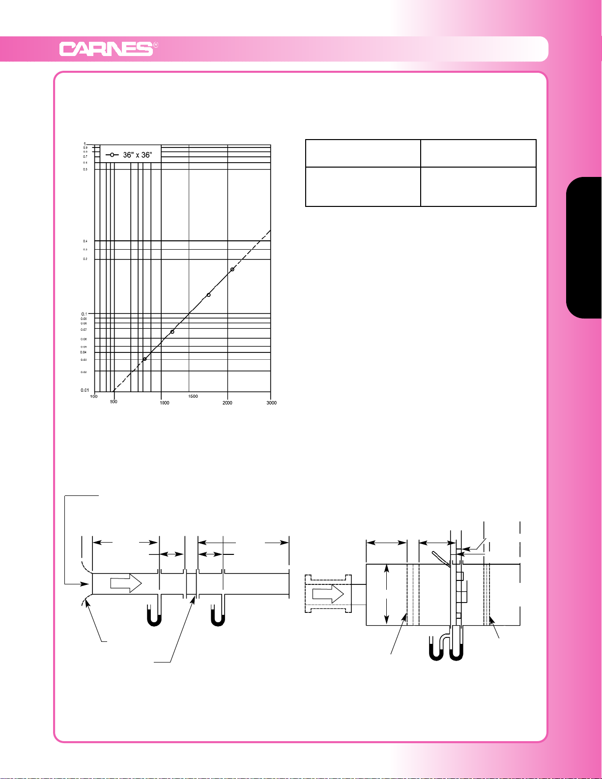
Figure 5.3 - Test Device Setup with Inlet and Outlet Ducts
P
s9
D ± 0.02D
Device being tested
6D min.
Figure 6.5 - Airflow Rate Measurement Setup -
Multiple Nozzle Chamber on Fan Inlet
M
M/5 min.
P
s5ΔPn
PL-A
PL-B
PL-5
PL-6
Variable
exhaust
system
Settling means
M/2 min.
38mm ± 6mm
(1.5 in. ± .025 in.)
38mm ± 6mm
(1.5 in. ± .025 in.)
t
d5
Galvanized Volume Control Dampers
Model: FDNB and FDQB
PL-9PL-YPL-X
P
s4
Inlet cone required
if attached to plenum
10D min.
D ± 0.02D
D
6
= Throat dia. of
largest nozzle
Settling means
2.5 D
6
min.
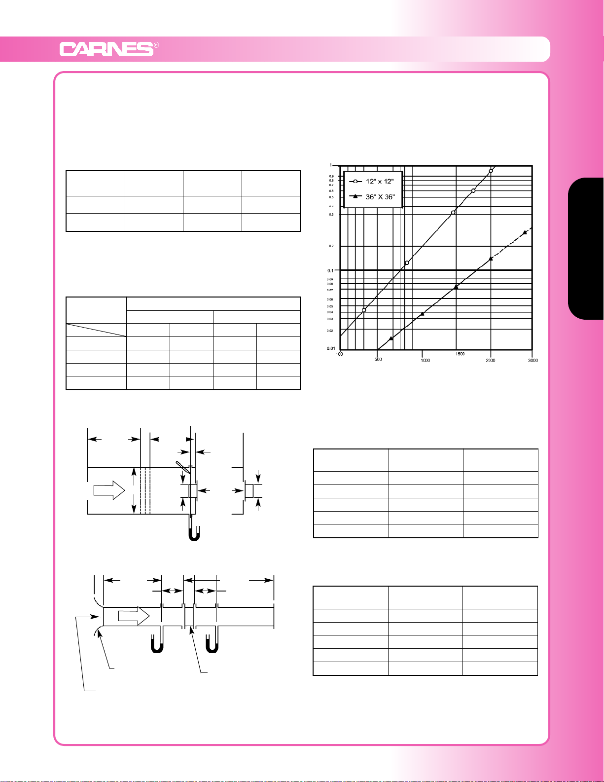
Pressure Drop
Static Pressure Drop (inches w.g.)
FREE AREA VELOCITY (FT/MIN)
Standard air - .075 lbs per cu ft
Ratings do not include the effects of a wire birdscreen
Test based on a 48” x 48” test size, 15 min test duration
Free Area Velocity
ft/min (m/s)
Pressure Drop
in w.g. (Pa)
1000 (5.08) 0.055
1500 (7.62) 0.100
2000 (10.16) 0.175
36 x 36
From supply system and
flow measuring section
Page 4
Volume Control Dampers
Volume Control Dampers
F-78 www.carnes.com
Low Leakage Volume Control Dampers - Aluminum
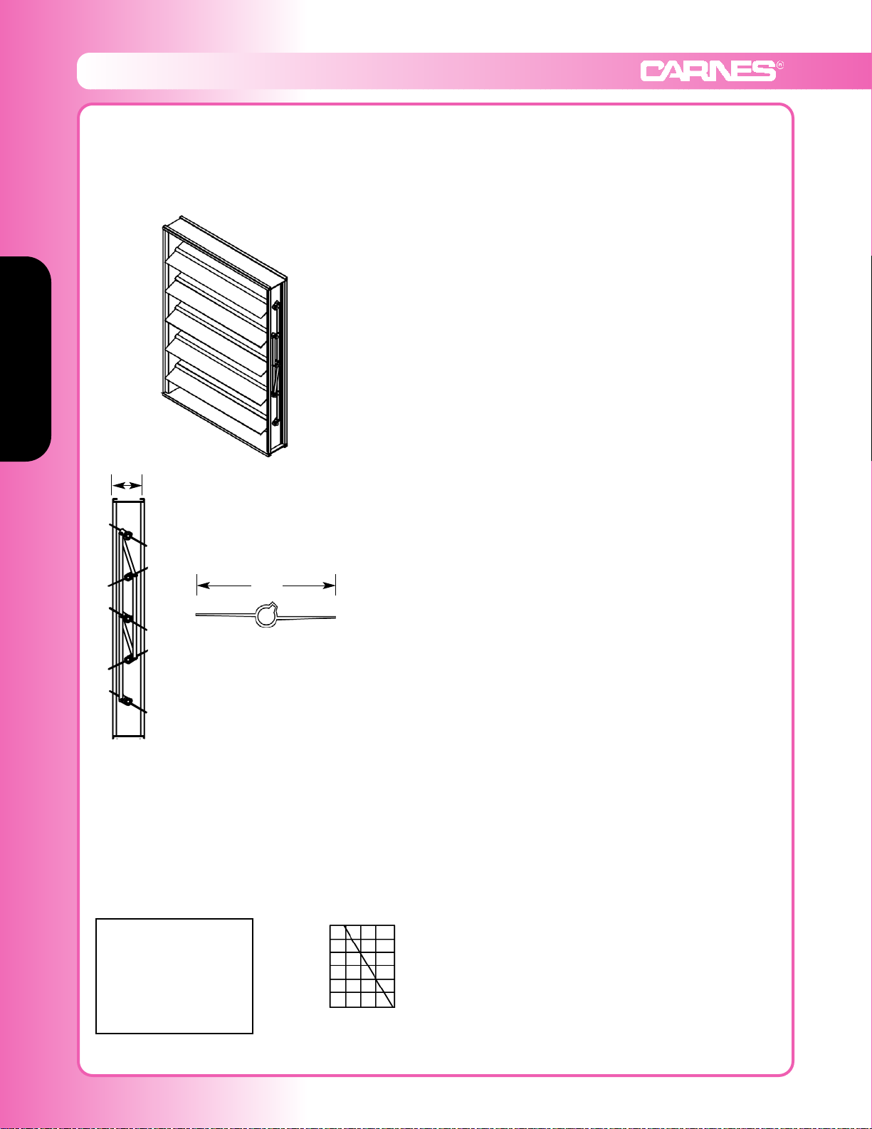
Model: FDCB Opposed Blade Channel Frame, FDHB Parallel Blade Channel Frame,
FDSB Opposed Blade Flanged Frame, FDTB Parallel Blade Flanged Frame
Model FDCB and FDHB
t Standard Specifications
Frame: .081 extruded aluminum
Blades: .125 extruded aluminum
Bearings: bronze oilite
Linkage: *concealed in frame
Axles: 1/2ӯ cast zinc with thrust bushing
Control Shaft: 1/2” x 6” long outboard support bearing supplied
with all single section dampers for field mounted actuators.
Factory-installed jackshaft supplied with all multi-section
dampers.
Maximum Size: 52”w x 72”h (single section)
Multi-section unlimited.
Minimum Size: 5”w x 4”h. 8” and under single blade.
*Over 36” wide or 48” high, blade linkage will be modified.
Options
• .125 Extruded Aluminum Frame (box frame)
• 1-1/2” .125 Extruded Aluminum Flanged Frame
• Blade Seals PVC (175°F)
• Blade Seals Silicone (400°F & #304 stainless steel bushing)
• Compression Jamb Seals (stainless steel)
• Hand Quadrant
• Factory Installed Pneumatic or Electric Actuators
• Position Switch
• Face and By-pass Damper
• Chain Operator
• Heresite Coated (air dry)
• Epoxy Coated (powder coated at 415°)
• Explosion-proof Enclosure for Actuator
Size Tested: 36”w x 36”h and 12”w x 12”h
12” wide -2600 FPM
24” -2200
36” -2000
48” -1700
52” -1600
FPM Table
4-1/2”
6-1/4”
Undersized 1/4”
Jackshafting provided over 52” wide
Pressure - up to 3” w.g. See pressure limit table
0 2 3
48”
36”
24”
12”
Maximum Damper
Section Width
Maximum Design Total Static
Pressure Inches Water Gage
Pressure Limitations
Page 5
Volume Control Dampers
www.carnes.com F-79
Volume Control Dampers
Aluminum Low Leakage Volume Control Dampers
Model: FDCB and FDHB
Damper
Width x Height
1 in. w.g. Class 4 in. w.g. Class 8 in. w.g. Class
12” x 12” 3.6 (Class 1A) 7.6 (Class 1A) 10.3 (Class 1A)
36” x 36” 0.5 (Class 1A) 5.6 (Class 1A) 20.8 (Class 1A)
Leakage Performance
Leakage - L/s/m² (ft³/min/ft²)
Note: At 1” w.g. 12” x 12” damper leaks 3.6 cfm per square foot.
Note: At 1” w.g. 36” x 36” damper leaks 0.5 cfm per square foot.
Note: Blade and jamb seals are required to meet the leakage
rates shown above.
AMCA Standards
Leakage Classification per AMCA publication 511-99.
Leakage,
ft³/min/ft²
Required Rating Extended Ranges (optional)
Class
0.25 kPa (1”) 1.0 kPa (4”) 2.0 kPa (8”) 3.0 kPa (12”)
1A 15.2 (3) 40.6 (8) 55.9 (11) 71.1 (14)
1 20.3 (3) 40.6 (8) 55.9 (11) 71.1 (14)
2 50.8 (10) 102 (20) 142 (28) 178 (35)
3 203 (40) 406 (80) 569 (112) 711 (140)
Pressure
Ratings shown are based on tests made in accordance with AMCA standard 500.
Free Area Velocity
ft/min (m/s)
Pressure drop
w.g. (Pa)
CFM
407 (2.0) .040 (1.24) 407
820 (4.1) .150 (4.97) 820
1234 (6.3) .340 (12.42) 1234
1641 (8.3) .610 (22.35) 1641
2057 (10.4) .950 (34.77) 2057
Pressure Drop
Static pressure drop (inches w.g.)
Free Area Velocity (ft/min)
Based on standard air - .075 lbs per cubic foot
FDCB, FDHB size tested: 36 x 36
Free Area Velocity
ft/min (m/s)
Pressure drop
w.g. (Pa)
CFM
392 (1.99) .005 (1.24) 3528
789 (4.01) .02 (4.97) 7100
1208 (6.14) .05 (12.42) 10,877
1598 (8.12) .09 (22.35) 14,382
2006 (10.19) .14 (34.77) 18,061
36” x 36” (914mm x 914mm)
12” x 12” (305mm x 305mm)
PL-2
AIRFLOW
Figure 5.5 - Test Device Setup with Inlet Chamber
P
s6
Device
being
tested
M/2 min.
PL-8
PL-Y
PL-X
PL-2
M/2 min.
W x H
W x H
PL-1
PL-2
PL-4
PL-Z
AIRFLOW
Figure 5.3 - Test Device Setup with Inlet and Outlet Ducts
P
s9
D ± 0.02D
Device being tested
6D min.
M
75mm ± 6mm
(3 in. ± .025 in.)
t
d5
PL-9
PL-YPL-X
P
s4
Inlet cone required
if attached to plenum
10D min.
D ± 0.02D
From supply system and flow measuring section
Page 6
Backdraft Dampers & Motorized Dampers
SECTION 8
F-80 www.carnes.com
Backdraft Dampers & Motorized Dampers
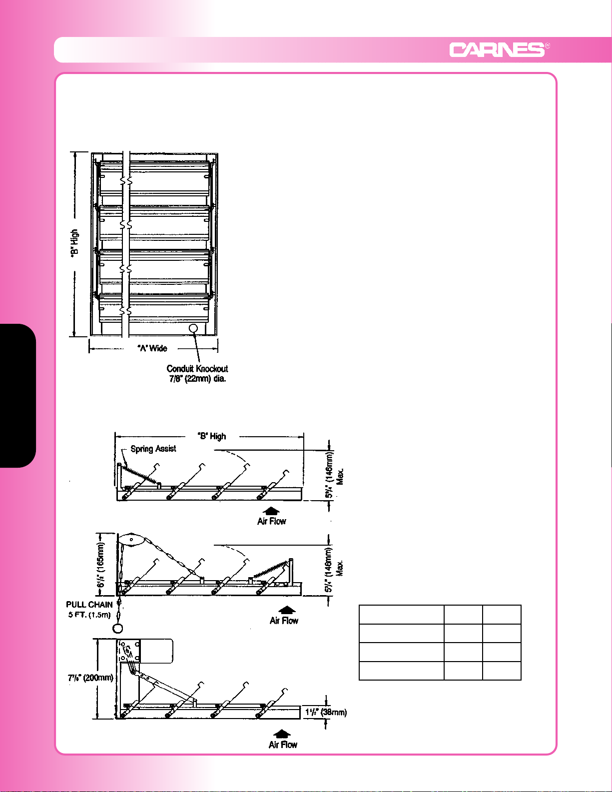
Horizontal or Vertical Exhaust Dampers; For All Models of Louvers and Penthouses
Model: JDHAA Automatic/Gravity, JDHAM Motorized, JDHAC Chain Operated
t Standard Specifications
Frame: .036” (1.6mm) 6063T6 aluminum
Blades: 24 gauge aluminum with double stiffening breaks
Finish: mill aluminum
Bearings: self lubricating nylon
Blade Pivots: 3/16” (5mm) plated steel
Linkage: galvanized steel; double linkage for width exceeding
20” (508mm)
Seals: felt between blades and polyurethane sponge at sill
Maximum Panel Size: 50”w x 72”h (1270mm x 1829mm)
Maximum Velocity: 1500 FPM (8 M/S)
Maximum Differential Pressure: 1” WG (250 N/M2)
Maximum Temperature: Damper 250°F (95°C); Motor 130°F (55°C)
Options
• POSC (Power Open-Spring Close)
• Standard Motor Voltage is 115-230/1/60
• Optional 24 VAC or 575 VAC
• Optional Transformers
• Optional Finishes
120V 240V
Idle Speed (RPM) 1.8 1.8
Idle Amps 0.244 0.137
Stall Amps 0.261 0.146
Face View
Model JDHAA Automatic
Model JDHAC Chain Operated
Model JDHAM Motor Operated
Spring Assist is field installed and is
recommended for face
velocity less than 600 FPM.
CAUTION: Motor kits are not suitable for
use in atmospheres or airflows containing
explosive or flammable products.
Actual Size = Nominal Size -1/4” (6mm)
Motor kits ship loose for field installation
Page 7
SECTION 9
www.carnes.com F-81
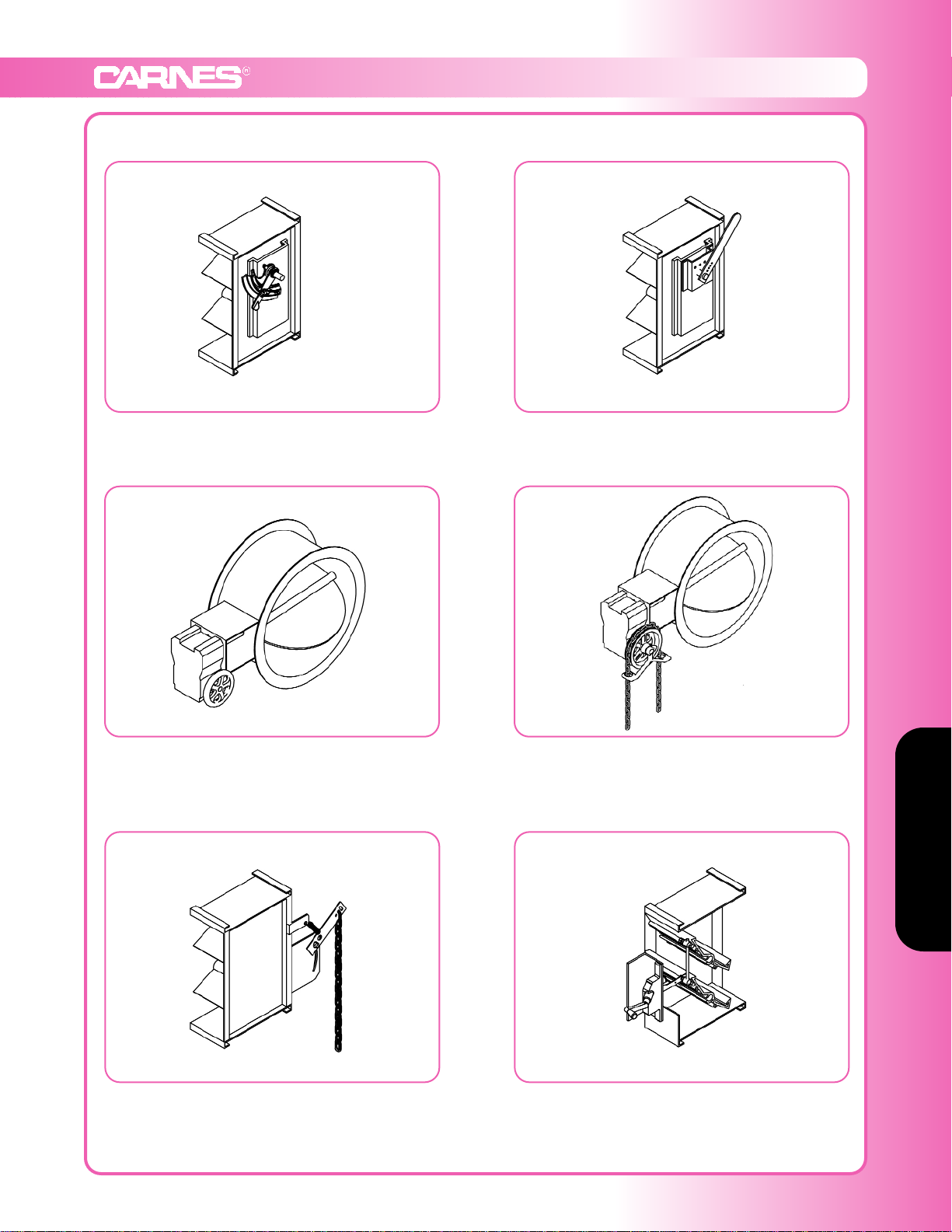
Manual Operators
Manual Operators for Louvers & Dampers
Hand Quadrant Operator #1
1/2” round shaft only
Hand Quadrant Operator #2
Heavy Duty
1/2” and 3/4” round shafts
Worm Gear with Hand Wheel
Operator #3
Heavy Duty
1/2” and 3/4” round shafts
Worm Gear with Chain Wheel
Operator #4
Heavy Duty
1/2” and 3/4” round shafts
Pull Chain
Operator #5
10 ft. chain standard
Heavy Duty Rotary
Hand Crank Operator #6
Mounted in the airstream
Primarily used on louvers
Page 8
Actuator Sizing Charts
SECTION 10
F-82 www.carnes.com
Actuator Sizing Chart
Opposed Blade Control Dampers
Options for Actuators:
1. End switch
2. Explosion-proof housing
CSA and UL Class I, II, III, Group C, D, E, F, G
Nema 7 Class 1, Group C and D
Nema 9 Class II, Group E, F, G
Consult Factory for other actuators.
Sq. ft. based on under 2” w.g. or 1200 FPM. For applications at 3” w.g. or 2500 FPM torque loading,
reduce sq. ft. by 25%. At 4” w.g. or 3000 FPM, reduce sq. ft. by 35%.
WITH JAMB SEALS WITHOUT JAMB SEALS
Type A Actuator
Models:
FXMBB (120V)
FXMBC (24V)
Max. Sq. Ft. - 3 S.F.
Spring Return
18# Torque
Type A Actuator
Models:
FXMBB (120V)
FXMBC (24V)
Max. Sq. Ft. - 7 S.F.
Spring Return
18# Torque
Type B Actuator
Models:
FXMBD (120V)
FXMBE (24V)
Max. Sq. Ft. - 6 S.F.
Spring Return
35# Torque
Type B Actuator
Models:
FXMBD (120V)
FXMBE (24V)
Max. Sq. Ft. - 14 S.F.
Spring Return
35# Torque
Type C Actuator
Models:
FXMBF (120V)
FXMBG (24V)
Max. Sq. Ft. - 14 S.F.
Spring Return
60# Torque
Type C Actuator
Models:
FXMBF (120V)
FXMBG (24V)
Max. Sq. Ft. - 30 S.F.
Spring Return
60# Torque
Type D Actuator
Models:
FXMBH (120V)
FXMBJ (24V)
Max. Sq. Ft. - 36 S.F.
Spring Return
133# Torque
Type D Actuator
Models:
FXMBH (120V)
FXMBJ (24V)
Max. Sq. Ft. - 65 S.F.
Spring Return
133# Torque
Type E Actuator
Models:
FXMBK (120V)
FXMBL (230V)
FXMBM (24V)
Max. Sq. Ft. - 50 S.F.
175# Torque
Type E Actuator
Models:
FXMBK (120V)
FXMBL (230V)
FXMBM (24V)
Max. Sq. Ft. - 85 S.F.
175# Torque
Page 9
Actuator Sizing Charts
www.carnes.com F-83
Actuator Sizing Charts
Actuator Sizing Chart
Parallel Blade Control Dampers & Louvers
Options for Actuators:
1. End switch
2. Explosion-proof housing
CSA and UL Class I, II, III, Group C, D, E, F, G
Nema 7 Class 1, Group C and D
Nema 9 Class II, Group E, F, G
Consult Factory for other actuators.
Sq. ft. based on under 2” w.g. or 1200 FPM. For applications at 3” w.g. or 2500 FPM torque loading,
reduce sq. ft. by 25%. At 4” w.g. or 3000 FPM, reduce sq. ft. by 35%.
WITH JAMB SEALS WITHOUT JAMB SEALS
Type A Actuator
Models:
FXMBB (120V)
FXMBC (24V)
Max. Sq. Ft. - 2.5 S.F.
Spring Return
18# Torque
Type A Actuator
Models:
FXMBB (120V)
FXMBC (24V)
Max. Sq. Ft. - 5 S.F.
Spring Return
18# Torque
Type B Actuator
Models:
FXMBD (120V)
FXMBE (24V)
Max. Sq. Ft. - 5 S.F.
Spring Return
35# Torque
Type B Actuator
Models:
FXMBD (120V)
FXMBE (24V)
Max. Sq. Ft. - 10 S.F.
Spring Return
35# Torque
Type C Actuator
Models:
FXMBF (120V)
FXMBG (24V)
Max. Sq. Ft. - 12 S.F.
Spring Return
60# Torque
Type C Actuator
Models:
FXMBF (120V)
FXMBG (24V)
Max. Sq. Ft. - 22 S.F.
Spring Return
60# Torque
Type D Actuator
Models:
FXMBH (120V)
FXMBJ (24V)
Max. Sq. Ft. - 25 S.F.
Spring Return
133# Torque
Type D Actuator
Models:
FXMBH (120V)
FXMBJ (24V)
Max. Sq. Ft. - 50 S.F.
Spring Return
133# Torque
Type E Actuator
Models:
FXMBK (120V)
FXMBL (230V)
FXMBM (24V)
Max. Sq. Ft. - 33 S.F.
175# Torque
Type E Actuator
Models:
FXMBK (120V)
FXMBL (230V)
FXMBM (24V)
Max. Sq. Ft. - 65 S.F.
175# Torque
Page 10
Louver and Damper Actuators
SECTION 11
F-84 www.carnes.com
Louver and Damper Actuators
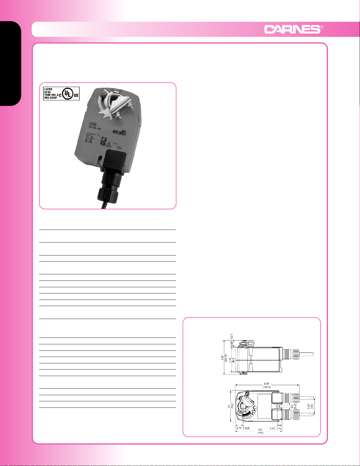
Model: FXMBB
Type A (120VAC) Belimo
On-off, spring return safety,
100 to 240 VAC Torque min. 18 in-lb,
for control of air dampers
t Application
For on-off, fail safe control of louvers and dampers in
HVAC systems. Actuator sizing should be done in accordance with the damper manufacturer’s specifications.
Control is on-off from an auxiliary contact, or a manual
switch.
The actuator is mounted directly to a damper shaft from
1/4” up to 1/2” in diameter by means of its universal clamp,
1/2” shaft centered at delivery. A crank arm and several
mounting brackets are available for applications where the
actuator cannot be direct coupled to the damper shaft.
Operation
The FXMBB series actuators provide true spring return
operation for reliable fail-safe application and positive
close off on air tight louvers and dampers. The spring
return system provides consistent torque to the damper
with, and without, power applied to the actuator. The
FXMBB series provides 95° of rotation and is provided with
a graduated position indicator showing 0° to 90°. The actuator may be stalled anywhere in its normal rotation without
the need of mechanical end switches. Power consumption
is reduced in holding mode. The actuator is double insulated so an electrical ground connection is not necessary.
Safety Note: Screw a conduit fitting into the actuator’s
bushing. Jacket the actuator’s input and output wiring with
suitable flexible conduit. Properly terminate the conduit in
a suitable junction box.
TECHNICAL DATA FXMBB
Power supply (nominal)
Power supply (tolerance)
100 to 240 VAC, 50/60 Hz
85 to 265 VAC, 50/60 Hz
Power consumption running: 2.5 W
holding: 1.3 W
Transformer sizing 4 VA (class 2 power source)
Electrical connection 3ft, 18 GA appliance cable
1/2” conduit connector
Overload protection electronic throughout 0° to 95° rotation
Electrical protection actuators are double insulated
Angle of rotation max 95°, adjust. with mechanical stop
Torque min. 18 in-lb [2 Nm]
Direction of rotation reversible with cw/ccw mounting
Position indication visual indicator, 0° to 95°
(0° spring return position)
Running time
(nominal)
motor: < 75 sec (0 to 18 in-lb)
spring: < 25 sec
@ -4°F to +122°F [-20°C to +50°C]
< 60 sec @ -22°F [-30°C]
Humidity 5 to 95% RH non-condensing
Ambient temperature -22°F to +122°F [-30°C to +50°C]
Storage temperature -40°F to +176°F [-40°C to +80°C]
Housing NEMA type 2 / IP42
Housing material UL94 - 5VA
Agency listings cULus listed acc. to UL 60730-1
Noise level max: running < 50 db (A)
spring return 62 db (A)
Servicing maintenance free
Quality standard ISO 9001
Weight 1.5 lbs (0.7 kg)
Dimensions (All numbers in brackets are mm)
Standard:
Ø 1/4” to 1/2”
1/4” to 5/16”
Page 11
Louver & Damper Actuators
www.carnes.com F-85
Louver and Damper Actuators
Louver and Damper Actuators
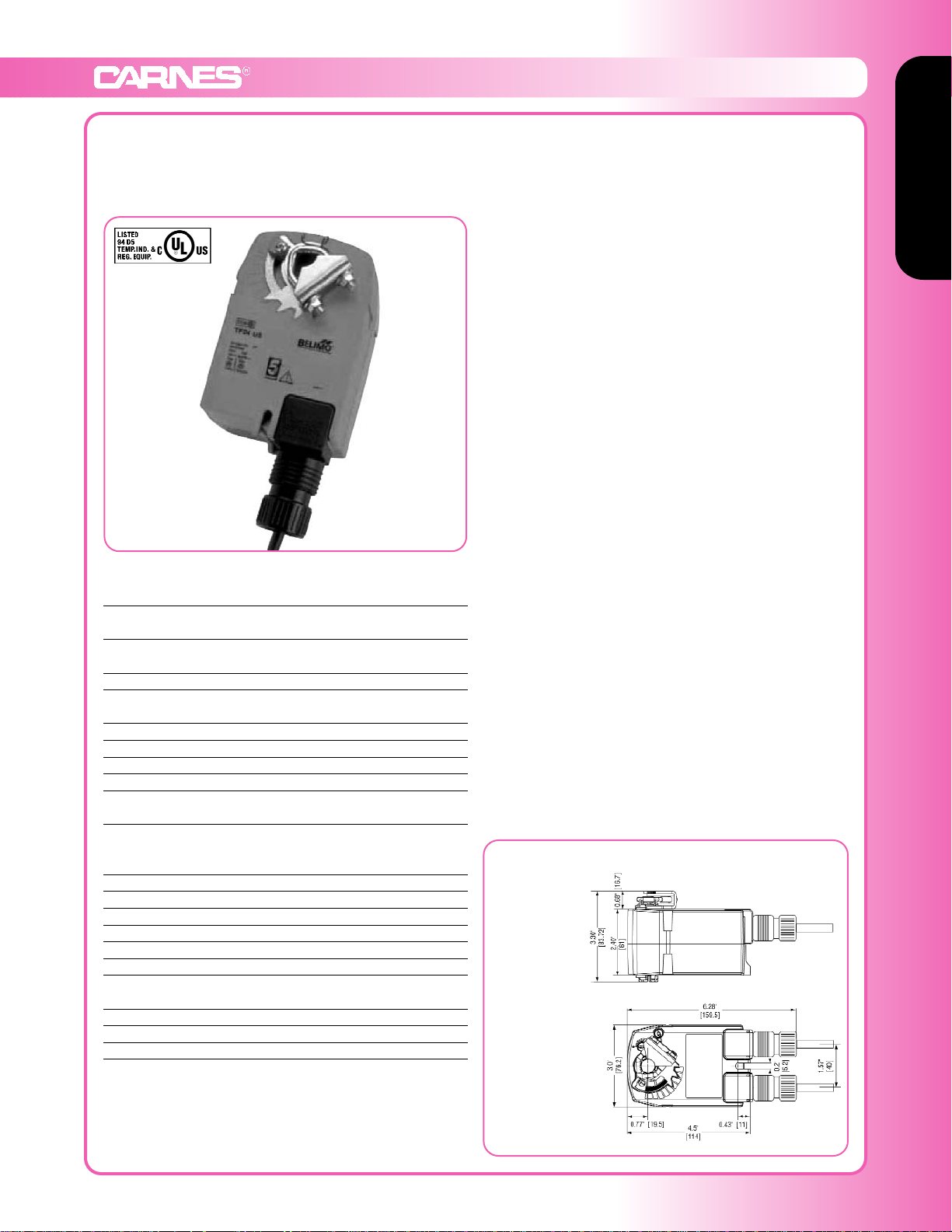
Model: FXMBC
Type A (24VAC) Belimo
On-off, spring return safety,
24V Torque min. 18 in-lb,
for control of air dampers
t Application
For on-off, fail safe control of louvers and dampers in
HVAC systems. Actuator sizing should be done in accordance with the damper manufacturer’s specifications.
Control is on-off from an auxiliary contact, or a manual
switch.
The actuator is mounted directly to a damper shaft from
1/4” up to 1/2” in diameter by means of its universal clamp,
1/2” shaft centered at delivery. A crank arm and several
mounting brackets are available for applications where the
actuator cannot be direct coupled to the damper shaft.
Operation
The FXMBC series actuators provide true spring return
operation for reliable fail-safe application and positive close
off on air tight louvers and dampers. The spring return
system provides consistent torque to the damper with, and
without, power applied to the actuator. The FXMBC series
provides 95° of rotation and is provided with a graduated
position indicator showing 0° to 90°. The actuator may be
stalled anywhere in its normal rotation without the need of
mechanical end switches. Power consumption is reduced
in holding mode.
Safety Note: Screw a conduit fitting into the actuator’s
bushing. Jacket the actuator’s input and output wiring with
suitable flexible conduit. Properly terminate the conduit in a
suitable junction box.
TECHNICAL DATA FXMBC
Power supply 24VAC ± 20%, 50/60 Hz
24VDC ± 10%
Power consumption running: 2.5 W
holding: 1.3 W
Transformer sizing 4 VA (class 2 power source)
Electrical connection 3ft, 18 GA appliance cable
1/2” conduit connector
Overload protection electronic throughout 0° to 95° rotation
Angle of rotation max 95°, adjust. with mechanical stop
Torque min. 18 in-lb [2 Nm]
Direction of rotation reversible with cw/ccw mounting
Position indication visual indicator, 0° to 95°
(0° spring return position)
Running time
(nominal)
motor: < 75 sec (0 to 18 in-lb)
spring: < 25 sec
@ -4°F to +122°F [-20°C to +50°C]
< 60 sec @ -22°F [-30°C]
Humidity 5 to 95% RH non-condensing
Ambient temperature -22°F to +122°F [-30°C to +50°C]
Storage temperature -40°F to +176°F [-40°C to +80°C]
Housing NEMA type 2 / IP42
Housing material UL94 - 5VA
Agency listings cULus listed acc. to UL 60730-1
Noise level max: running < 50 db (A)
spring return 62 db (A)
Servicing maintenance free
Quality standard ISO 9001
Weight 1.5 lbs (0.7 kg)
Dimensions (All numbers in brackets are mm)
Standard:
Ø 1/4” to 1/2”
1/4” to 5/16”
Page 12
Louver and Damper Actuators
Louver & Damper Actuators
F-86 www.carnes.com
Louver and Damper Actuators
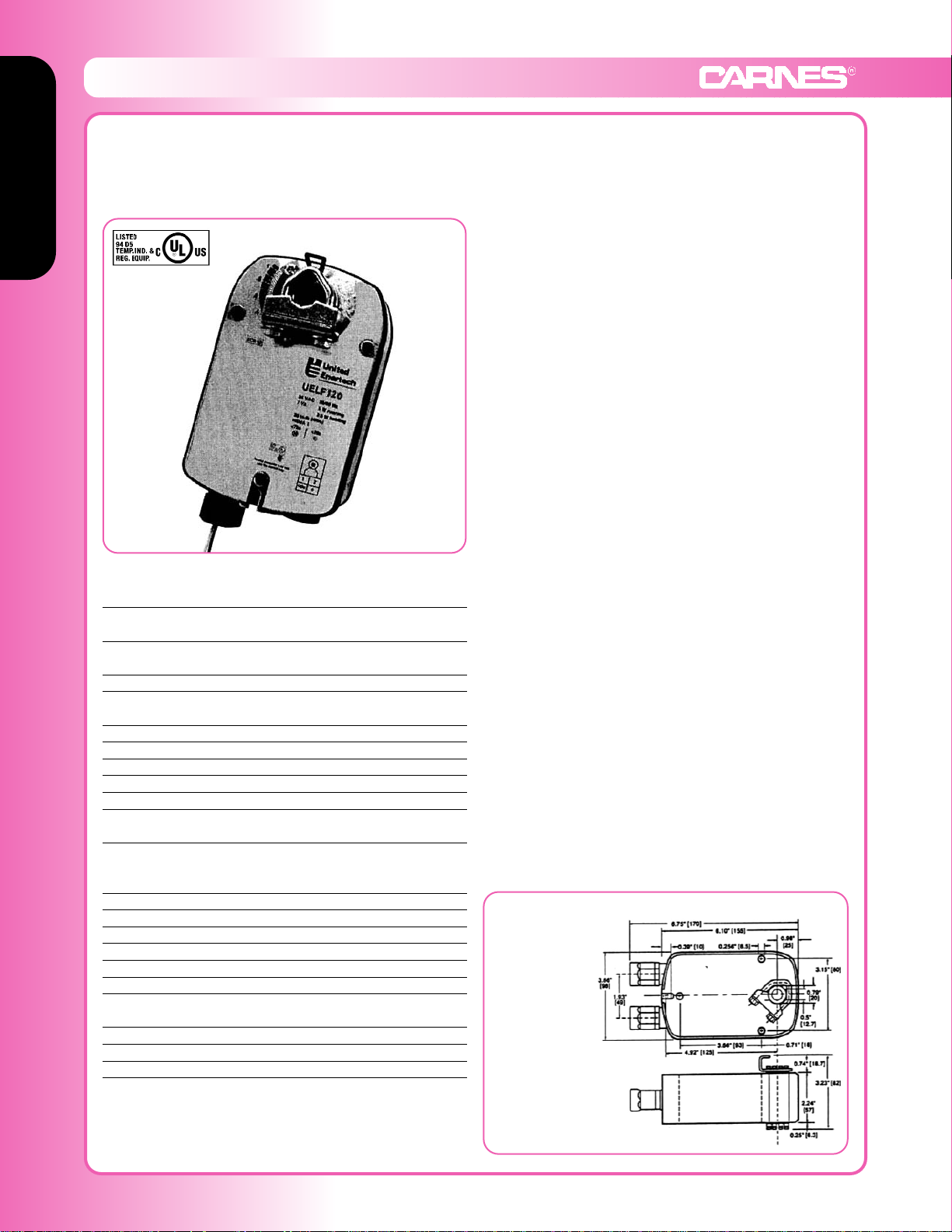
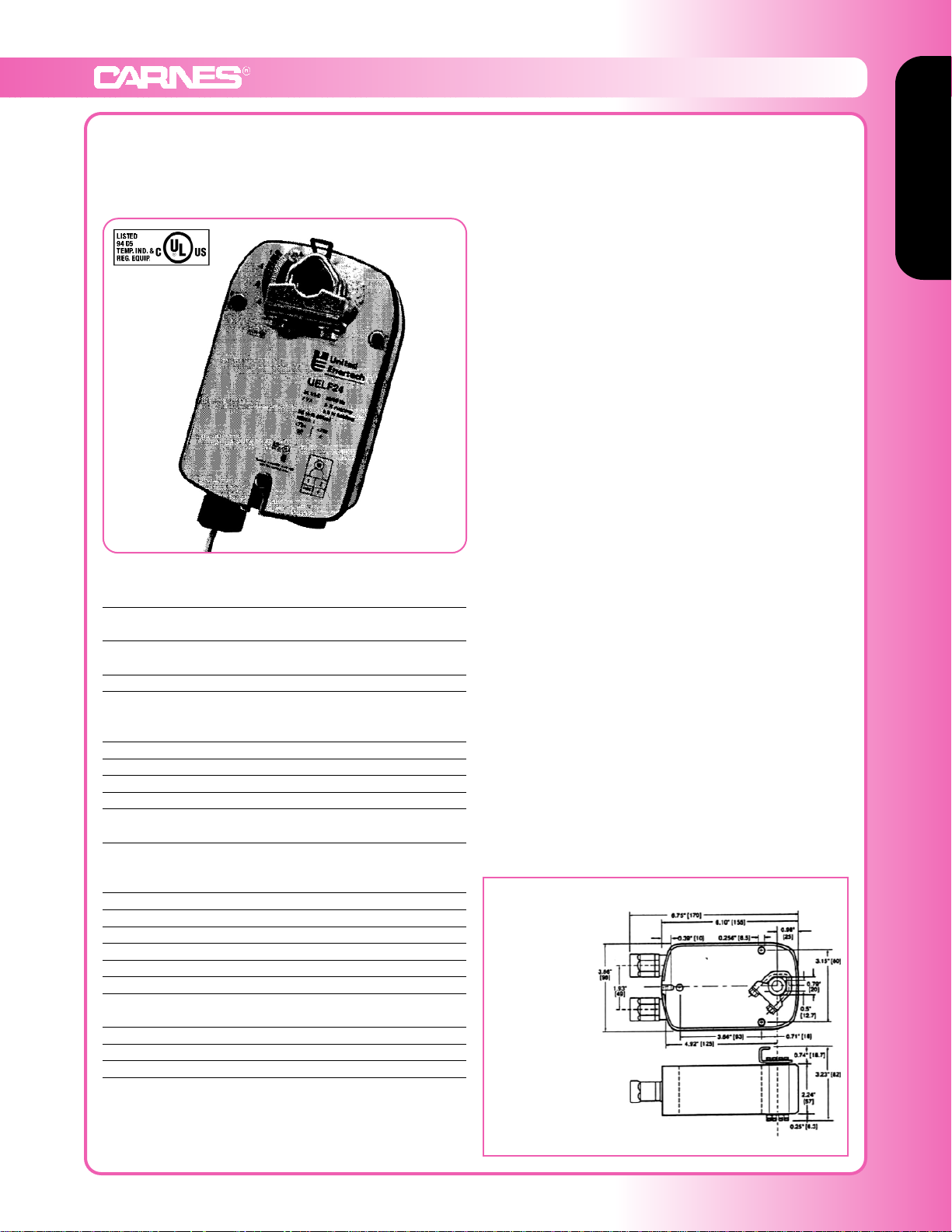
Model: FXMBD
Type B (120VAC)
On-off, spring return safety,
120 VAC Torque min. 35 in-lb,
for control of air dampers
t Application
For on-off, fail safe control of louvers and dampers in
HVAC systems. Actuator sizing should be done in accordance with the damper manufacturer’s specifications.
Control is on-off from an auxiliary contact, or a manual
switch.
The actuator is mounted directly to a damper shaft from
3/8” up to 1/2” in diameter by means of its universal clamp,
1/2” shaft centered at delivery. For shafts up to 3/4” use
K6-1 accessory. A crank arm and several mounting brackets are available for applications where the actuator cannot
be direct coupled to the damper shaft.
Operation
The FXMBD series actuators provide true spring return
operation for reliable fail-safe application and positive close
off on air tight louvers and dampers. The spring return
system provides consistent torque to the damper with, and
without, power applied to the actuator. The FXMBD series
provides 95° of rotation and is provided with a graduated
position indicator showing 0° to 90°. The actuator may be
stalled anywhere in its normal rotation without the need of
mechanical end switches. Power consumption is reduced
in holding mode. The actuator is double insulated so an
electrical ground connection is not necessary.
Five Year Warranty
Two Year “unconditional” warranty from date of installation. For the following three years,
a conditional warranty applies. Under this conditional warranty, the consequences of
ordinary wear and tear, damage due to negligence or improper use, or other causes
beyond our control are excluded from warranty coverage. Attempts at field repair or
modifications will null and void warranty. Products found defective will be replaced or
repaired at seller’s discretion. Seller is not responsible for any field labor.
TECHNICAL DATA FXMBD
Power supply 120 VAC ±10%
50/60 Hz
Power consumption running: 5.5 W
holding: 3.5 W
Transformer sizing 7.5 VA (class 2 power source)
Electrical connection (2) 18”, 18 GA single conductors
1/2” conduit connector
Overload protection electronic throughout 0° to 95° rotation
Electrical protection actuators are double insulated
Angle of rotation max 95°, adjust. with mechanical stop
Torque 35 in-lb [4 Nm] constant torque
Direction of rotation reversible with cw/ccw mounting
Position indication visual indicator, 0° to 95°
(0° spring return position)
Running time
(nominal)
motor: < 40 to 75 sec
spring: < 25 sec
@ -4°F to +122°F [-20°C to +50°C]
< 60 sec @ -22°F [-30°C]
Humidity 5 to 95% RH non-condensing
Ambient temperature -22°F to +122°F [-30°C to +50°C]
Storage temperature -40°F to +176°F [-40°C to +80°C]
Housing NEMA type 2 / IP54
Housing material zinc coated steel
Agency listings UL 873, CSA 4813 02
Noise level max: running < 50 db (A)
spring return 62 db (A)
Servicing maintenance free
Quality standard ISO 9001
Weight 3.4 lbs (1.54 kg)
Dimensions
(All numbers in brackets are mm)
Standard:
Ø 3/8” to 1/2”
1/4” to 5/16”
Optional:
Ø 1/2” to 3/4”
w/K6-1 accessory
Page 13
Louver & Damper Actuators
www.carnes.com F-87
Louver and Damper Actuators
Louver and Damper Actuators
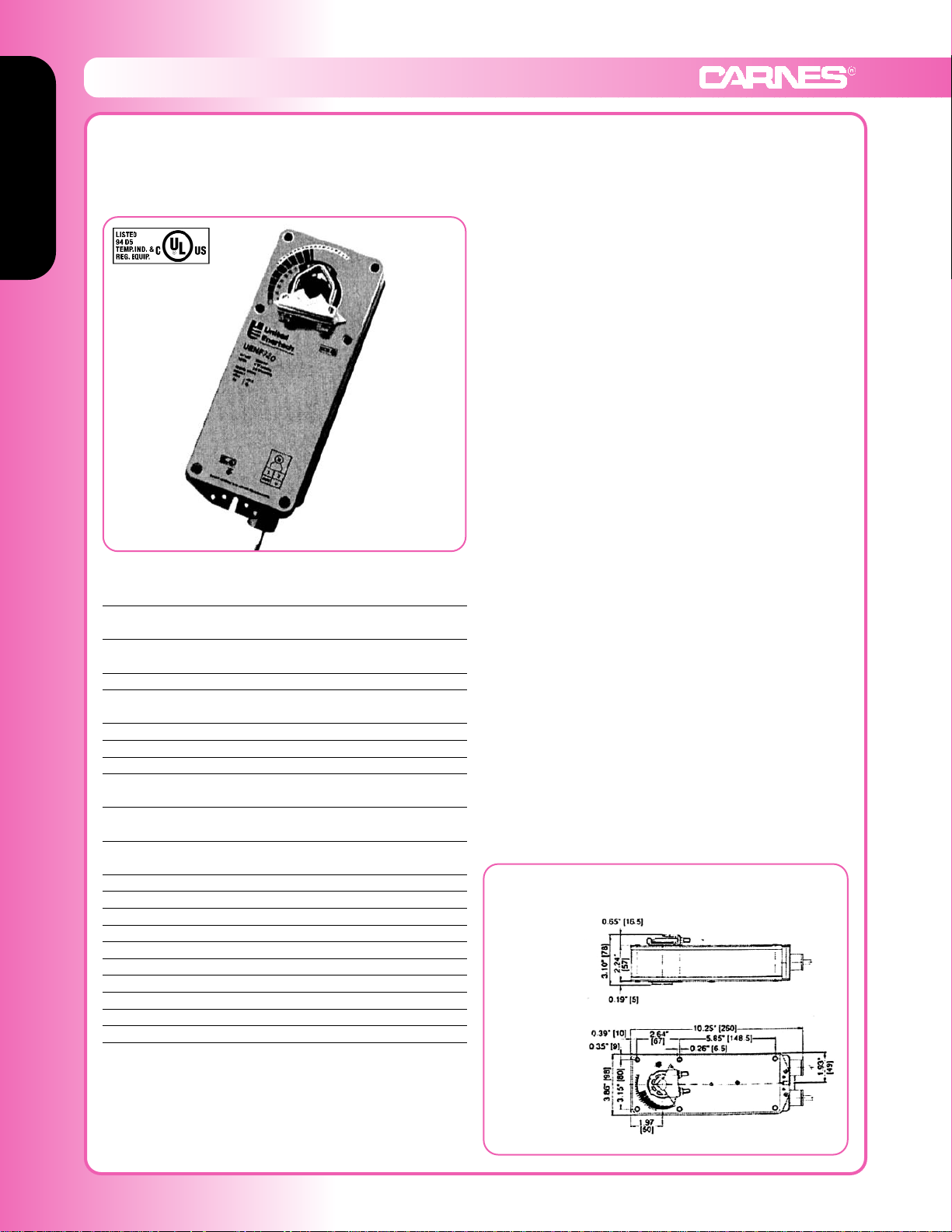
Model: FXMBE
Type B (24VAC)
On-off, spring return safety,
24V Torque min. 35 in-lb,
for control of air dampers
t Application
For on-off, fail safe control of louvers and dampers in
HVAC systems. Actuator sizing should be done in accordance with the damper manufacturer’s specifications.
Control is on-off from an auxiliary contact, or a manual
switch.
The actuator is mounted directly to a damper shaft from
3/8” up to 1/2” in diameter by means of its universal clamp,
1/2” shaft centered at delivery. For shafts up to 3/4” use
K6-1 accessory. A crank arm and several mounting brackets are available for applications where the actuator cannot
be direct coupled to the damper shaft.
Operation
The FXMBE series actuators provide true spring return
operation for reliable fail-safe application and positive close
off on air tight louvers and dampers. The spring return
system provides consistent torque to the damper with, and
without, power applied to the actuator. The FXMBE series
provides 95° of rotation and is provided with a graduated
position indicator showing 0° to 90°. The actuator may be
stalled anywhere in its normal rotation without the need of
mechanical end switches. Power consumption is reduced
in holding mode.
Five Year Warranty
Two Year “unconditional” warranty from date of installation. For the following three years,
a conditional warranty applies. Under this conditional warranty, the consequences of
ordinary wear and tear, damage due to negligence or improper use, or other causes
beyond our control are excluded from warranty coverage. Attempts at field repair or
modifications will null and void warranty. Products found defective will be replaced or
repaired at seller’s discretion. Seller is not responsible for any field labor.
TECHNICAL DATA FXMBE
Power supply 24 VAC ±20% 50/60 Hz
24 VDC ±10%
Power consumption running: 5 W
holding: 2.5 W
Transformer sizing 7 VA (class 2 power source)
Electrical connection (2) 18”, 18 GA single conductors (-S models
use appliance cable for switch)
1/2” conduit connector
Overload protection electronic throughout 0° to 95° rotation
Angle of rotation max 95°, adjust. with mechanical stop
Torque 35 in-lb [4 Nm]
Direction of rotation reversible with cw/ccw mounting
Position indication visual indicator, 0° to 95°
(0° spring return position)
Running time
(nominal)
motor: < 40 to 75 sec
spring: < 25 sec
@ -4°F to +122°F [-20°C to +50°C]
< 60 sec @ -22°F [-30°C]
Humidity 5 to 95% RH non-condensing
Ambient temperature -22°F to +122°F [-30°C to +50°C]
Storage temperature -40°F to +176°F [-40°C to +80°C]
Housing NEMA type 1
Housing material zinc coated steel
Agency listings UL 873 listed, CSA 4813 02 certified
Noise level max: running < 50 db (A)
spring return 62 db (A)
Servicing maintenance free
Quality standard ISO 9001
Weight 3.1 lbs (1.40 kg)
Dimensions (All numbers in brackets are mm)
Standard:
Ø 3/8” to 1/2”
1/4” to 5/16”
Optional:
Ø 1/2” to 3/4”
w/K6-1 accessory
Page 14
Louver and Damper Actuators
Louver & Damper Actuators
F-88 www.carnes.com
Louver and Damper Actuators
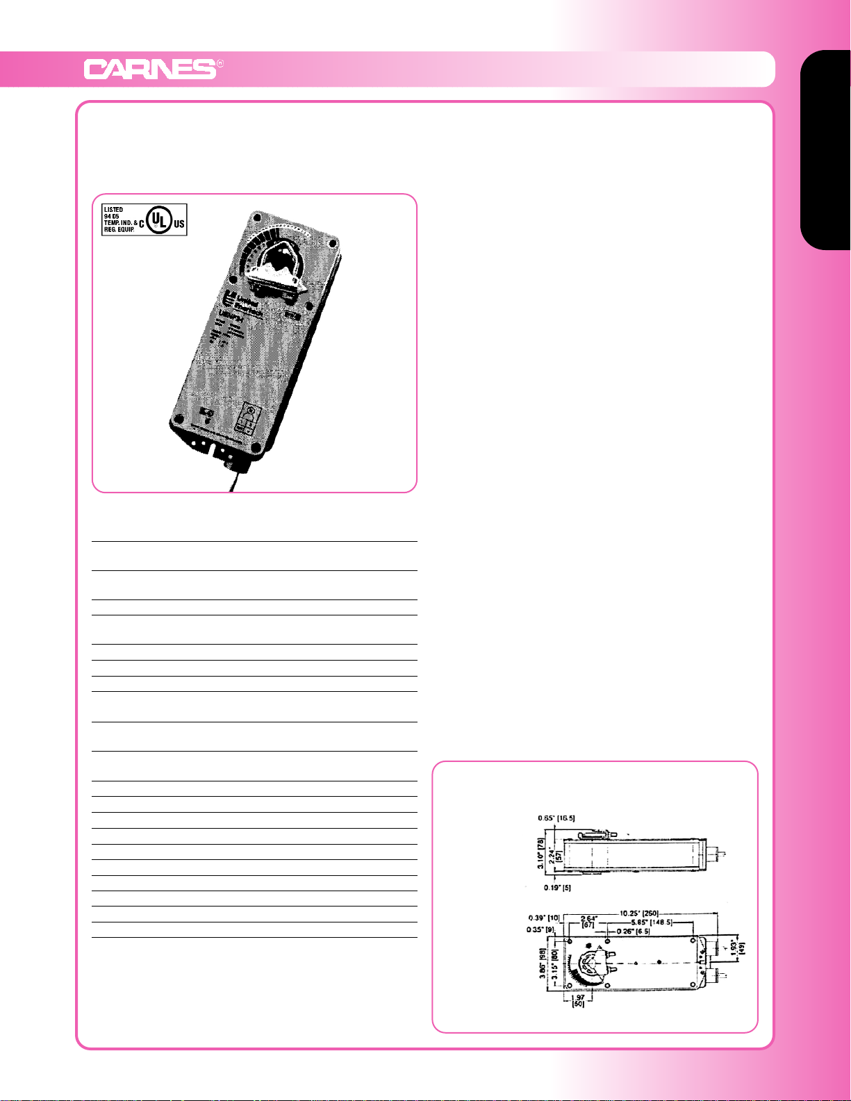
Model: FXMBF
Type C (120VAC)
On-off, spring return safety,
120 VAC Torque min. 60 in-lb,
for control of air dampers
t Application
For on-off, fail safe control of louvers and dampers in
HVAC systems. Actuator sizing should be done in accordance with the damper manufacturer’s specifications.
Control is on-off from an auxiliary contact, or a manual
switch.
The actuator is mounted directly to a damper shaft up to
1/2” in diameter by means of its universal clamp, or up to a
1.05” jackshaft by removing the clamp insert. A crank arm
and several mounting brackets are available for applications where the actuator cannot be direct coupled to the
damper shaft.
Operation
The FXMBF series actuators provide true spring return
operation for reliable fail-safe application and positive close
off on air tight louvers and dampers. The spring return
system provides consistent torque to the damper with, and
without, power applied to the actuator. The FXMBF series
provides 95° of rotation and is provided with a graduated
position indicator showing 0° to 95°. The actuator may be
stalled anywhere in its normal rotation without the need of
mechanical end switches.
Five Year Warranty
Two Year “unconditional” warranty from date of installation. For the following three years,
a conditional warranty applies. Under this conditional warranty, the consequences of
ordinary wear and tear, damage due to negligence or improper use, or other causes
beyond our control are excluded from warranty coverage. Attempts at field repair or
modifications will null and void warranty. Products found defective will be replaced or
repaired at seller’s discretion. Seller is not responsible for any field labor.
TECHNICAL DATA FXMBF
Power supply 120 VAC ±10%
50/60 Hz
Power consumption running: 6 W
holding: 3.5 W
Transformer sizing 7 VA (class 1 power source)
Electrical connection (3) 18”, 18 GA single conductors
1/2” conduit connector
Overload protection electronic throughout 0° to 95° rotation
Angle of rotation 95°, adjust. 30 to 95° w/accessories
Torque 60 in-lb [7 Nm] constant torque
Direction of rotation spring return can be selected by
cw/ccw mounting
Position indication visual indicator, 0° to 95°
(0° spring return position)
Running time
(nominal)
motor: < 75 sec
spring: < 60 sec
Humidity 5 to 95% RH non-condensing
Ambient temperature -22°F to +122°F [-30°C to +50°C]
Storage temperature -40°F to +176°F [-40°C to +80°C]
Housing NEMA type 1
Housing material zinc coated steel
Agency listings UL 873 listed, CSA 4813 02 certified
Noise level max: 45 db (A)
Servicing maintenance free
Quality standard ISO 9001
Weight 7.3 lbs (3.3 kg)
Dimensions (All numbers in brackets are mm)
Standard:
Ø 1/2” to 1.05”
Optional:
Ø 3/8” to 3/4”
w/K4 US clamp
Page 15
Louver & Damper Actuators
www.carnes.com F-89
Louver and Damper Actuators
Louver and Damper Actuators
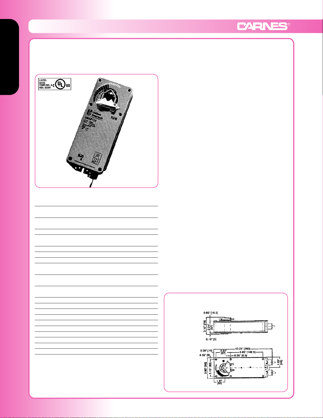
Model: FXMBG
Type C (24VAC)
On-off, spring return safety,
24 V Torque min. 60 in-lb,
for control of air dampers
t Application
For on-off, fail safe control of louvers and dampers in
HVAC systems. Actuator sizing should be done in accordance with the damper manufacturer’s specifications.
Control is on-off from an auxiliary contact, or a manual
switch.
The actuator is mounted directly to a damper shaft up to
1/2” in diameter by means of its universal clamp, or up to a
1.05” jackshaft by removing the clamp insert. A crank arm
and several mounting brackets are available for applications where the actuator cannot be direct coupled to the
damper shaft.
Operation
The FXMBG series actuators provide true spring return
operation for reliable fail-safe application and positive close
off on air tight louvers and dampers. The spring return
system provides consistent torque to the damper with, and
without, power applied to the actuator. The FXMBG series
provides 95° of rotation and is provided with a graduated
position indicator showing 0° to 95°. The actuator may be
stalled anywhere in its normal rotation without the need of
mechanical end switches.
Five Year Warranty
Two Year “unconditional” warranty from date of installation. For the following three years,
a conditional warranty applies. Under this conditional warranty, the consequences of
ordinary wear and tear, damage due to negligence or improper use, or other causes
beyond our control are excluded from warranty coverage. Attempts at field repair or
modifications will null and void warranty. Products found defective will be replaced or
repaired at seller’s discretion. Seller is not responsible for any field labor.
TECHNICAL DATA FXMBG
Power supply 24 VAC ±20% 50/60 Hz
24 VDC ±10%
Power consumption running: 5 W
holding: 2.6 W
Transformer sizing 8 VA (class 1 power source)
Electrical connection (2) 18”, 18 GA single conductors
1/2” conduit connector
Overload protection electronic throughout 0° to 95° rotation
Angle of rotation max 95°, adjust. with mechanical stop
Torque 60 in-lb [7 Nm] constant torque
Direction of rotation spring return can be selected by cw/ccw
mounting
Position indication visual indicator, 0° to 95°
(0° spring return position)
Running time
(nominal)
motor: < 75 sec
spring: < 60 sec
Humidity 5 to 95% RH non-condensing
Ambient temperature -22°F to +122°F [-30°C to +50°C]
Storage temperature -40°F to +176°F [-40°C to +80°C]
Housing NEMA type 1
Housing material zinc coated steel
Agency listings UL 873 listed, CSA 4813 02 certified
Noise level max: 45 db (A)
Servicing maintenance free
Quality standard ISO 9001
Weight 6.6 lbs (3.0 kg)
Dimensions (All numbers in brackets are mm)
Standard:
Ø 1/2” to 1.05”
Optional:
Ø 3/8” to 3/4”
w/K4 US clamp
Page 16
Louver and Damper Actuators
Louver & Damper Actuators
F-90 www.carnes.com
Louver and Damper Actuators
Model: FXMBH
Type D (120VAC)
On-off, spring return safety,
120 VAC Torque min. 133 in-lb,
for control of air dampers
t Application
For on-off, fail safe control of louvers and dampers in
HVAC systems. Actuator sizing should be done in accordance with the damper manufacturer’s specifications.
Control is on-off from an auxiliary contact, or a manual
switch.
The actuator is mounted directly to a damper shaft up to
1/2” in diameter by means of its universal clamp, or up to a
1.05” jackshaft by removing the clamp insert. A crank arm
and several mounting brackets are available for applications where the actuator cannot be direct coupled to the
damper shaft.
Operation
The FXMBH series actuators provide true spring return
operation for reliable fail-safe application and positive close
off on air tight louvers and dampers. The spring return
system provides consistent torque to the damper with, and
without, power applied to the actuator. The FXMBH series
provides 95° of rotation and is provided with a graduated
position indicator showing 0° to 95°. The actuator may be
stalled anywhere in its normal rotation without the need of
mechanical end switches.
The FXMBH uses a brushless DC motor which is
controlled by an Application Specific Integrated Circuit
(ASIC). The ASIC monitors and controls the actuator’s
rotation and provides a digital rotation sensing function to
prevent damage to the actuator in a stall condition. The
actuator may be stalled anywhere in its normal rotation
without the need of mechanical end switches.
TECHNICAL DATA FXMBH
Power supply 120 VAC ±10%
50/60 Hz
Power consumption running: 6 W
holding: 2.3 W
Transformer sizing 10 VA (class 1 power source)
Electrical connection (3) 18”, 18 GA single conductors
1/2” conduit connector
Overload protection electronic throughout 0° to 95° rotation
Angle of rotation 95°, adjust. 30 to 95° w/accessories
Torque 133 in-lb [7 Nm] constant torque
Direction of rotation spring return can be selected by
cw/ccw mounting
Position indication visual indicator, -0° to 95°
(-0° spring return position)
Running time 150 sec. constant, independent of load,
spring return < 20 sec
Humidity 5 to 95% RH non-condensing
Ambient temperature -22°F to +122°F [-30°C to +50°C]
Storage temperature -40°F to +176°F [-40°C to +80°C]
Housing NEMA type 1
Housing material zinc coated steel
Agency listings UL 873 listed, CSA 4813 02 certified
Noise level max: 45 db (A)
Servicing maintenance free
Quality standard ISO 9001
Weight 6.9 lbs (3.1 kg)
Dimensions
(All numbers in brackets are mm)
Standard:
Ø 1/2” to 1.05”
Optional:
Ø 3/8” to 3/4”
w/K4 US clamp
Five Year Warranty
Two Year “unconditional” warranty from date of installation. For the following three years,
a conditional warranty applies. Under this conditional warranty, the consequences of
ordinary wear and tear, damage due to negligence or improper use, or other causes
beyond our control are excluded from warranty coverage. Attempts at field repair or modifications will null and void warranty. Products found defective will be replaced or repaired
at seller’s discretion. Seller is not responsible for any field labor.
Page 17
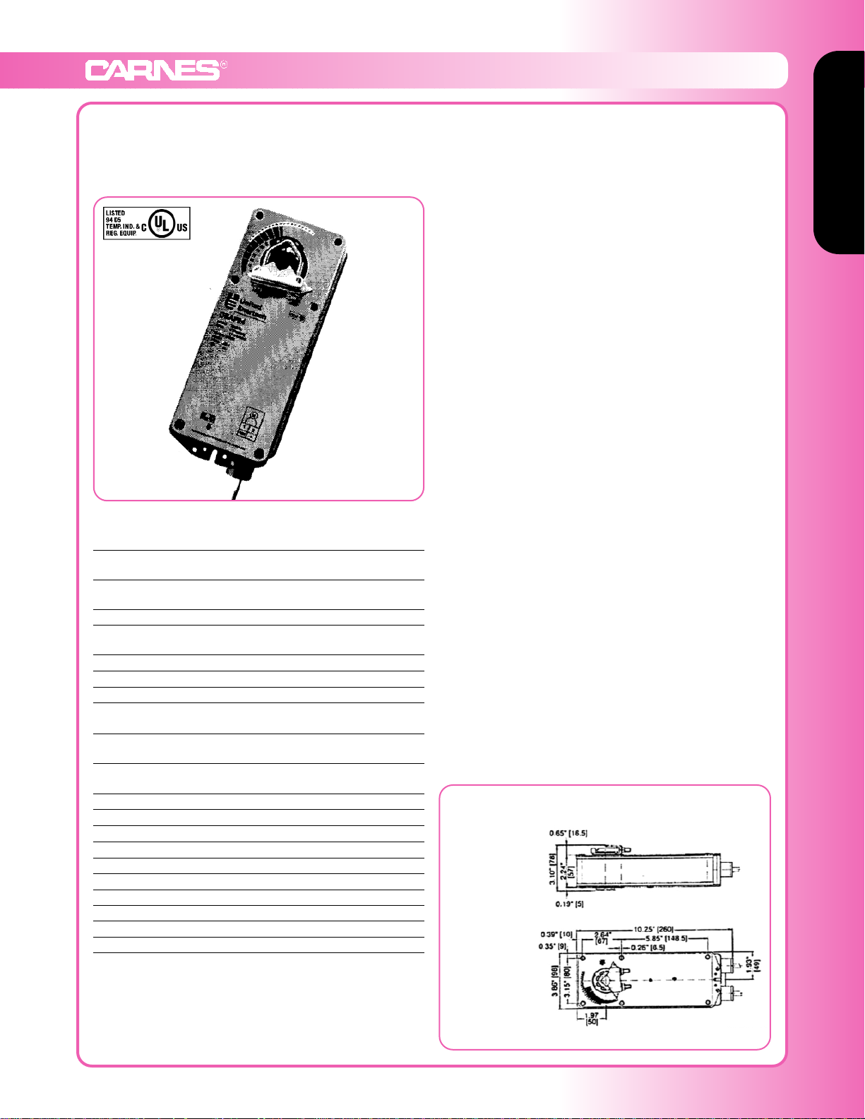
Louver & Damper Actuators
www.carnes.com F-91
Louver and Damper Actuators
Louver and Damper Actuators
Model: FXMBJ
Type D (24VAC)
On-off, spring return safety,
24V Torque min. 133 in-lb,
for control of air dampers
t Application
For on-off, fail safe control of louvers and dampers in
HVAC systems. Actuator sizing should be done in accordance with the damper manufacturer’s specifications.
Control is on-off from an auxiliary contact, or a manual
switch.
The actuator is mounted directly to a damper shaft up to
1/2” in diameter by means of its universal clamp, or up to a
1.05” jackshaft by removing the clamp insert. A crank arm
and several mounting brackets are available for applications where the actuator cannot be direct coupled to the
damper shaft.
Operation
The FXMBJ series actuators provide true spring return
operation for reliable fail-safe application and positive close
off on air tight louvers and dampers. The spring return
system provides consistent torque to the damper with, and
without, power applied to the actuator. The FXMBJ series
provides 95° of rotation and is provided with a graduated
position indicator showing 0° to 95°. The actuator may be
stalled anywhere in its normal rotation without the need of
mechanical end switches.
The FXMBJ uses a brushless DC motor which is controlled
by an Application Specific Integrated Circuit (ASIC). The
ASIC monitors and controls the actuator’s rotation and
provides a digital rotation sensing function to prevent
damage to the actuator in a stall condition. The actuator
may be stalled anywhere in its normal rotation without the
need of mechanical end switches.
TECHNICAL DATA FXMBJ
Power supply 24 VAC ±20% 50/60 Hz
24 VDC ±10%
Power consumption running: 5 W
holding: 1.5 W
Transformer sizing 10 VA (class 1 power source)
Electrical connection (2) 18”, 18 GA single conductors
1/2” conduit connector
Overload protection electronic throughout 0° to 95° rotation
Angle of rotation 95°, adjust. 30 to 95° w/accessories
Torque 133 in-lb [7 Nm] constant torque
Direction of rotation spring return can be selected by cw/ccw
mounting
Position indication visual indicator, -0° to 95°
(-0° spring return position)
Running time 150 sec. constant, independent of load,
spring return < 20 sec
Humidity 5 to 95% RH non-condensing
Ambient temperature -22°F to +122°F [-30°C to +50°C]
Storage temperature -40°F to +176°F [-40°C to +80°C]
Housing NEMA type 1
Housing material zinc coated steel
Agency listings UL 873 listed, CSA 4813 02 certified
Noise level max: 45 db (A)
Servicing maintenance free
Quality standard ISO 9001
Weight 6.0 lbs (2.7 kg)
Dimensions (All numbers in brackets are mm)
Standard:
Ø 1/2” to 1.05”
Optional:
Ø 3/8” to 3/4”
w/K4 US clamp
Five Year Warranty
Two Year “unconditional” warranty from date of installation. For the following three years,
a conditional warranty applies. Under this conditional warranty, the consequences of
ordinary wear and tear, damage due to negligence or improper use, or other causes
beyond our control are excluded from warranty coverage. Attempts at field repair or
modifications will null and void warranty. Products found defective will be replaced or
repaired at seller’s discretion. Seller is not responsible for any field labor.
Page 18
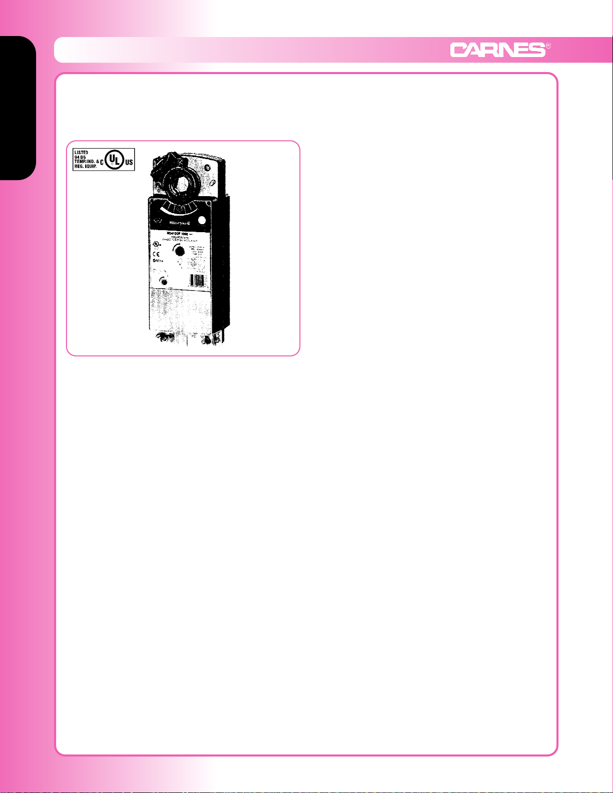
Louver and Damper Actuators
Louver & Damper Actuators
F-92 www.carnes.com
Louver and Damper Actuators
Model: FXMBK (120V), FXMBL (230V), FXMBM (24V)
Type E Honeywell
Fast-acting, two position actuators
t Application
The FXMBK, FXMBL and FXMBM Fast-Acting, Two
Position Actuators are spring return direct coupled actuators (DCA) for on/off signal from a single-pole, single-throw
(spst) controller. Reversible mounting allows actuator to be
used for either clockwise (cw) or counterclockwise (ccw)
spring rotation.
The FXMBK, FXMBL and FXMBM DCA are designed to
operate reliable in smoke control systems requiring
Underwriter’s Laboratories Inc. UL555S ratings up to
350°F.
Features
• 175 lb-in. (20 N•m) minimum driving torque at 350°F
(176°C)
• Reversible mounting facilitates use in either clockwise
(cw) or counterclockwise (ccw) spring rotation
• Integral spring return ensures level of return torque
• Stainless steel internal sprint
• Fifteen-second spring return timing
• No special cycling required during long-term holding
(See operation section)
• No audible noise during holding
• Patent pending design eliminates need for limit
switches to reduce power consumption
• Models available for 24, 120, and 230 Vac applications
• Ninety-five degree angle of rotation
• Actuator holds rated torque at reduced power level
• Die-cast aluminum housing
• Housing design allows flush mounting to damper
• High-temperature indicator included
• Self-centering shaft adapter (SCSA), patent pending
FXMBK and FXMBL
• High temperature Teflon® lead wires
• Designed to operate reliable in smoke control systems
requiring Underwriter’s Laboratories Inc. UL555S
ratings up to 350°F
• Models available with integral high temperature (350°F)
SPST position-indicating switches (7°, 85° stroke)
FXMBM
• Double-insulation rating
• Halogen-free, silicone-free leadwires
• Models available with integral high temperature (350°F)
SPST position-indicating switches (7°, 85° stroke)
 Loading...