

Page 1
FORM 40001
INSTALLATION, OPERATING AND MAINTENANCE INSTRUCTIONS
Fire Dampers - Static and Dynamic
CAUTION! DO NOT INSTALL, USE OR OPERATE THIS EQUIPMENT UNTIL THIS
MANUAL HAS BEEN READ AND UNDERSTOOD. READ AND SAVE THESE INSTRUCTIONS FOR FUTURE USE.
GENERAL NOTES:
When UL is referred to in this document, it represents UL/ULC. This installation instruction
applies to Fire Dampers (static, dynamic, curtain, single, and multi blade types) mounted in the plane
of an UL approved fire partition. The dampers are designed for operation in the vertical or horizontal position with blades running horizontal. The dampers shall not be compressed or stretched into
the opening. Transportation and installation of the dampers shall be handled with the sleeve or
frame. Do not lift the damper with the blades or actuator. Special care shall be given to the damper
before installation and after to insure it is protected against dirt, weather, mortar and drywall dust, wall textures, and paint. Any of these
conditions could cause the damper not to operate correctly and void the warranty. Suitable access to inside duct is to be provided for
inspection and replacement of parts such as heat response devices and actuators per NFPA 90A and local authority having jurisdiction.
As with all joints, contractor must seal duct collar connections in the field after installation.
1. Opening Preparation/Clearances:
The fire barrier opening shall be larger than the damper to allow for thermal expansion and ease of installation. When steel stud/
gypsum or wood stud/gypsum partitions are being used then refer to Fig. 1-3 for additional information and details.
A. Dampers Assemblies Using Two Angles Methods (see note 4a) shall be a minimum of 1/8” (3mm) per linear foot
(305mm) of height and width of sleeved assembly up to a maximum of 1-1/2” (38mm) and a minimum of 1/4” (6mm). For Static Systems
the maximum single section curtain damper is 60” x 60” (1524mm x 1524mm) vertical and 40” x 40” (1016mm x 1016mm) or 48” x 48”
(1219mm x 1219mm) in vertical or horizontal mountings. For Dynamic Systems the maximum single section curtain damper is
36” x 36” (914mm x 914mm) in horizontal mountings, based on type “A” dampers. The maximum single section curtain damper is
36” x 48” (914mm x 1219mm) in vertical mountings and 24” x 24” (610mm x 610mm) in horizontal mountings, based on type “A”
dampers. The maximum single section multi blade damper is 36” x 48” (914mm x 1219mm) in vertical or horizontal mountings. This
method is acceptable for 1-1/2 and 3 hour fire dampers. See Underwriters Laboratories Listings for maximum multiple assembly sizes.
B. Dampers Assemblies Using One Angle Methods (see note 4b) shall be minimum of 1/8” (3mm) per linear foot (305mm)
of height and width of sleeved assembly up to a maximum of 1-1/2” (38mm) and a minimum of 1/4” (6mm). The maximum single
section is the same as in A above. The maximum multi-section is 108” wide or 108” height up to 36 square feet. This method is
acceptable for 1-1/2 hour fire dampers mounted in a masonry/concrete or steel stud/gypsum wall only.
C. Dampers Assemblies Using No Angles Methods (see note 4c) shall be a minimum of 1/4” (6mm) and a maximum of
1/2” (13mm). The maximum single section is the same as in A above. The maximum multi-section is 42” wide x 48” high. This method
is acceptable for 1-1/2 hour fire dampers mounted in a masonry/concrete or steel stud/gypsum wall only.
2. Sleeves shall be of the SAME GAUGE or heavier as the duct to which it is attached, if one of the breakaway connection is used as
defined in the SMACNA Fire, Smoke, and Radiation Damper Guide for HVAC Systems (Fig. 4-6) and in NFPA 90A. Gauges shall
conform to SMACNA or ASHRAE duct standards. Sleeves shall not extend beyond the fire barrier more than 6” (152mm) unless an
actuator or factory installed access door is supplied, then the sleeve may extend up to 16” (406mm). Sleeve shall terminate at both sides
of wall within dimensions shown. If a rigid connection is used, then the sleeve shall be minimum of 16 gauge for dampers up to
36” (914mm) wide by 24” (610mm) high and 14 gauge for dampers exceeding 36” (914mm) wide by 24” (610mm) high.
Round and oval breakaway connections must use either a 4” (102mm) wide draw band or #10 (M5) sheet metal screws spaced equally around the circumference of the duct as follows: 3 screws for duct sizes 22” (559mm) and smaller; 5 screws for duct sizes greater
than 22” (559mm) and up to and including 36” (914mm); 8 screws for duct sizes greater than 36” (914mm). Refer to SMACNA Fire,
Smoke, and Radiation Damper Guide for HVAC Systems for information on Ductmate, Nexus, Ward, TDC and TDF systems and any
additional information (Fig. 5-6). A sleeve may not be required if the damper frame is of sufficient size and shape so the mounting angles
can be directly fastened to it.
FORM 40001, Page 1
CARNES COMPANY 448 S. Main St., P. O. Box 930040, Verona, WI 53593-0040 Phone: (608)845-6411 Fax: (608)845-6470 www.carnes.com
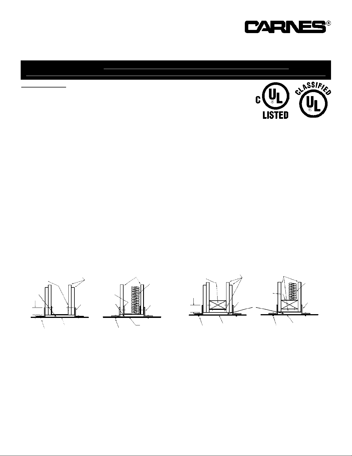
Fig. 1: Metal Stud/Gypsum Wall Design
1” Min.
Thermal
Gap
Thermal
Gap
2-1/2” Min. Stud
or Runner
1/2” Min. Gypsum
Wallboard
2-1/2” Min. Stud
or Runner
1/2” Min. Gypsum
Wallboard
Retaining
Angle
Damper Sleeve
Fasten with a 1/4” bolt/nut
1/2” welds, #10 sheet metal
screws, or 3/16” pop rivets
on 10” centers.
Damper Sleeve
Fasten with a 1/4” bolt/nut
1/2” welds, #10 sheet metal
screws, or 3/16” pop rivets
on 10” centers.
Retaining
Angle
1-1/2” Mineral
Fiber Blanket
In Cavity, If
Required
Fig. 2: Wood Stud/Gypsum Wall Design
1” Min.
Thermal
Gap
2-1/2” Min. Stud
or Runner
1/2” Min. Gypsum
Wallboard
2-1/2” Min.
Stud or
Runner
1/2” Min. Gypsum
Wallboard
Retaining
Angle
Damper Sleeve
Fasten with a 1/4” bolt/nut
1/2” welds, #10 sheet metal
screws, or 3/16” pop rivets
on 10” centers.
Damper Sleeve
Fasten with a 1/4” bolt/nut
1/2” welds, #10 sheet metal
screws, or 3/16” pop rivets
on 10” centers.
Retaining
Angle
1-1/2” Mineral
Fiber Blanket
In Cavity, If
Required
WALL RATING - 2 HR.
WALL RATING - 1 HR.
WALL RATING - 2 HR.
WALL RATING - 1 HR.
Page 2
4. Methods of Securing Damper in Opening:
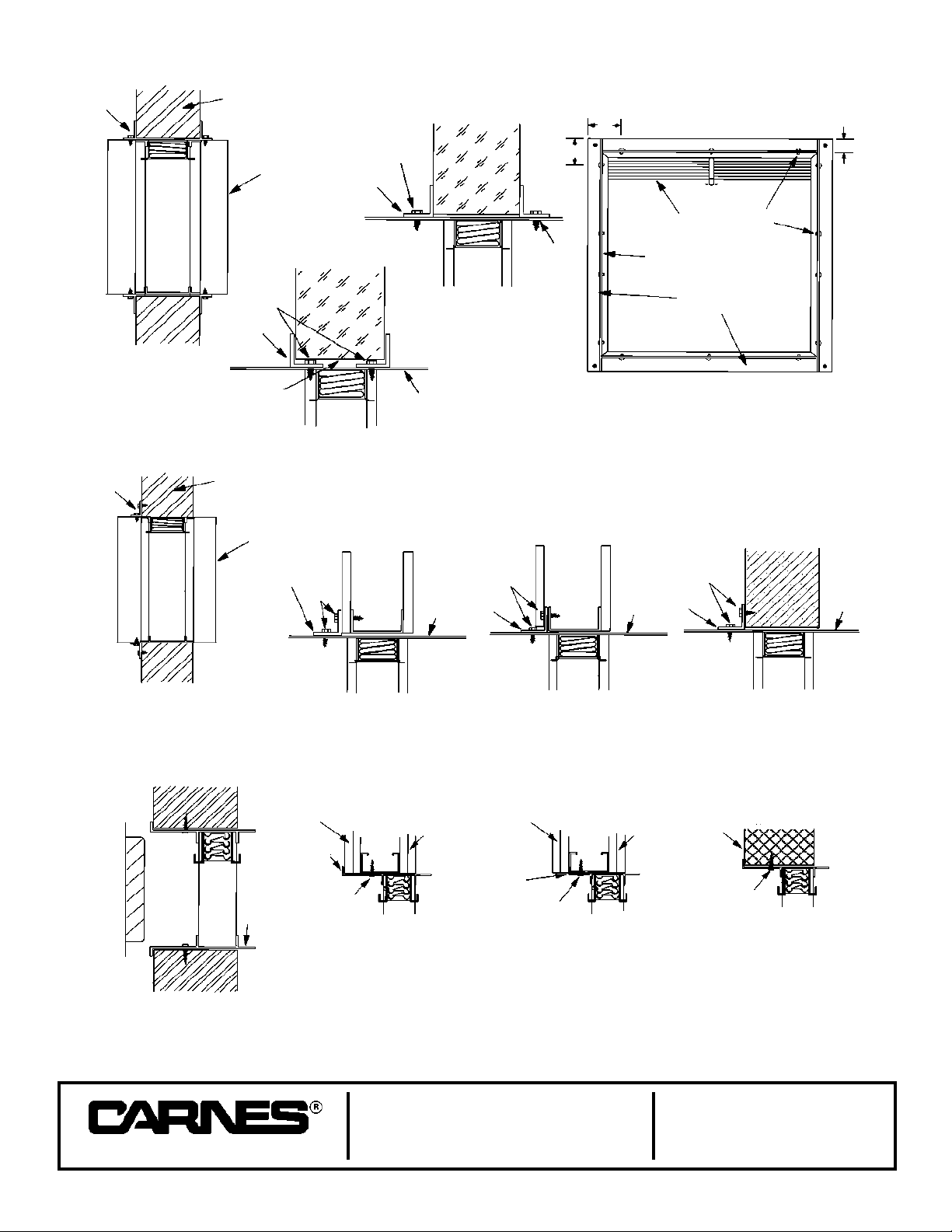
A. Two Angle (Two Sided) Method: This method is the oldest and commonly used. This method is approved for use in UL
approved concrete/masonry partitions, steel stud/gypsum walls, and wood stud/gypsum walls. In this method 2 sets of angles are used
to secure the damper in the opening, one on each side of the partition (see Fig. 7). Two Angle Method is approved for 1-1/2 and 3 hour
dampers, vertical or horizontal orientation, and any maximum size multi-section UL approved damper (see Underwriters Laboratories
Listings for maximum assembly sizes). Angles shall be minimum of 1-1/2” x 1-1/2” (37mm x 37mm) by 16 gauge. Angles are to be
fastened to the sleeve on 6” centers with #10 (M5) sheet metal screws, 3/16” (5mm) steel pop rivets, 1/2” (13mm) tack welds, or 1/4”
(6mm) diameter nut and bolts with not more than 2” (51mm) from each end with a minimum of two connections per side/leg.
The angles are to overlap the partition a minimum of 1” (25mm). These angles may be of a unit type construction and may or may not
be fastened to each other at the corners. When the duct work terminates at the damper or installation prohibits angles from turning
out/away from the wall, the retaining angle shall be reversed (leg turned into the opening) providing the size of the opening is increased
by an amount equal to twice the combined thickness of the angle and the height of the screw or bolt head to maintain expansion
clearances. See note 1A for information on clearances. See Fig. 7 for detailed drawings of installations.
B. One Angle (Single Sided) Method: In this method one set of angles are used to secure the damper in the opening. This
method is approved for use in UL approved concrete/masonry partitions and steel stud/gypsum walls. Only one side of the fire partition
will have the angles installed (see Fig. 8). One Angle Method is approved for 1-1/2 hour dampers only, vertical and horizontal (angles
on top side only) orientations, and the maximum size shall be 108” wide or 108” high up to 36 square feet and up to the maximum multisection UL approved damper size (see Underwriters Laboratories Listings for maximum assembly sizes). Angle shall be a minimum of
1-1/2” x 1-1/2” (37mm x 37mm) by 16 gauge. Angles are to be fastened to the sleeve on 6” centers with #10 (M5) sheet metal screws,
3/16” (5mm) steel pop rivets, 1/2” (13mm) tack welds, or 1/4” (6mm) diameter nut and bolts with not more than 2” (51mm) from each
end with a minimum of two connections on each side/leg top and bottom. The angles are also to be fastened to the fire partition with: in
concrete/masonry partitions with #10 (M5) self-tapping concrete anchors or concrete screws on 6” (152mm) centers and must engage
the fire partition a minimum of 1-1/2” (38mm); in steel stud/gypsum partitions secure the angles to the partition with #10 (M5) screws
long enough to penetrate the J-Runners and E-Stud by a minimum of 3/8” (10mm). Use a minimum of two fasteners per side. The angles
are to overlap the partition a minimum of 1” (25mm). These angles may be of a unit type construction and may or may not be fastened
to each other at the corners. When the duct work terminates at the damper or installation prohibits angles from turning out/away from
the wall, the retaining angle shall be reversed (leg turned into the opening) providing the size of the opening is increased by an amount
equal to twice the combined thickness of the angle and the height of the screw or bolt head to maintain expansion clearances. Angles
can be placed in front of or behind the drywall attaching directly to the steel studs or masonry. Carnes’ Frame Retaining Angles can be
used in place of the angle mentioned above. See note 1B for information on clearances. See Fig. 8 for detailed drawings of
installations.
C. No Angles Method: In this method No Angles are used to secure the damper in the opening. This method is approved for
use in UL approved concrete/masonry partitions and steel stud/gypsum walls. This method uses a minimum 3/4” (19mm) flange on one
end of the sleeve. The damper/sleeve assembly is placed in the opening so that the flange rest flush up to the partition, then the
fasteners are placed through the sleeve into the partition (see Fig. 9). No Angle Method is approved for 1-1/2 hour dampers only,
vertical and horizontal (flange on top side only) orientations, and the maximum size shall be 42” (1067mm) wide by 48” (1219mm) high
up to the maximum multi-section UL approved damper size (see Underwriters Laboratories Listings for maximum assembly sizes). The
sleeve flange shall be a minimum of 3/4” (19mm) high by 20 gauge steel. If a flange/angle is added, it shall be a minimum of 1” x 1”
(25mm x 25mm) by 18 gauge steel and fastened with #10 (M5) bolts or screws, 1/2” (13mm) welds, or 3/16” (5mm) rivets to the sleeve,
at a maximum spacing of 6” (152mm) o.c., not more than 2” (51mm) from each end with a minimum of two fasteners per side. The sleeve
is to be fastened to the fire partition with: in concrete/masonry partitions with #10 self-tapping concrete anchors or concrete screws on
6” (152mm) centers and must engage the fire partition a minimum of 1-1/2” (38mm); in steel stud/gypsum partitions secure the angles
to the partition with #10 (M5) screws long enough to penetrate the J-Runners and E-Stud by a minimum of 3/8” (10mm). Use a
minimum of two fasteners per side. The sleeve flange can be placed in front of or behind the drywall attaching directly to the steel studs
or masonry. Be sure to not stretch the damper when securing it into the partition. Stretching the damper can cause it to bind up and
prevent it from operating properly. Carnes’ Frame Retaining Angles can be used in place of the angle mentioned above. See note 1C
for information on clearances. See Fig. 9 for detailed drawings of installations.
FORM 40001, Page 2
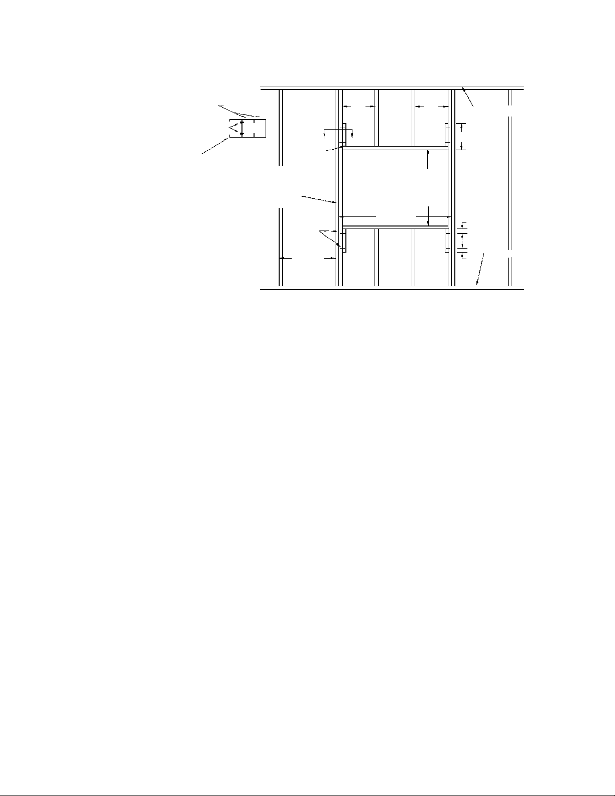
Fig. 3: Metal or Wood Stud Wall
24” O.C.
Max.
2 Panhead
Screws
Floor
Runner
Ceiling Runner
Runner
90 Blend
Width
Height
See UL Directory for
Maximum Allowable
Opening Size Per
Fire Damper Model.
12”
2”
2”
16”
16”
A
A
Double Stud Not
Required on
Penetrations
36” x 36”
Or Smaller
2-1/2” Min. Runner
2-1/2” Min. Stud
Screws
Section A-A
Note: Gypsum panels screwed to all
studs and runner flanges, 12”
o.c. maximum surrounding
opening. All fasteners are to be
UL approved per UL design.
3. Multi-Section and “Damper to Sleeve” Connections:
Damper shall be secured to the sleeve and to each other (when joined to make multiple damper assemblies) with #10 sheet metal
screws, 1/4” (6mm) nut and bolts, 1/4” (6mm) tack welds, 3/16” (5mm) steel rivets, or clinching (toggle) on 6” (152mm) centers.
Page 3
BREAKAWAY CONNECTIONS
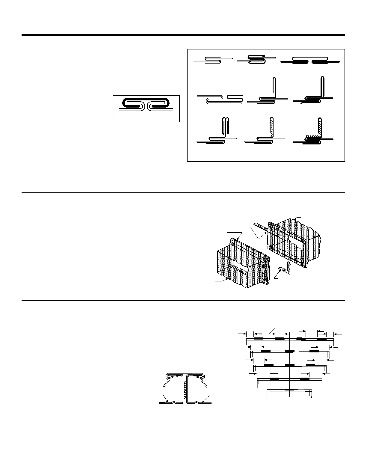
Traditional Breakaway Style Transverse Joints
Transverse joints illustrated at right have always been approved
as breakaway connections. SMACNA testing has also approved
the following variations as breakaway connections.
• Standing “S” joints can be applied with #10 sheet metal screws
(through joint and duct) subject to the following limitations:
maximum 2 screws in each side and in bottom joint.
• Transverse joints illustrated can
be applied as top and bottom joints
with Drive Slip - side joints in duct
heights up to 20” (508mm).
Round and Oval Duct Breakaway Connections
Round or flat oval ducts connected to Type R, CR or CO damper
collars may use #10 sheet metal screws as follows:
• Ducts to 22” (558mm) wide (or diameter) and smaller may use
3 screws.
• Ducts larger than 22” (558mm) wide (or diameter) and up to 36”
(914mm) diameter may use 5 screws.
• Ducts larger than 36” (914mm) wide (or diameter) may use 8 screws.
NOTE: All breakaway connections described may have duct sealant applied in accordance with SMACNA recommendations.
FORM 40001, Page 3
Fig. 4
Plain “S” Slip Hemmed “S” Slip Double “S” Slip
Inside Slip Joint Standing “S” Standing “S” (Alt.)
Standing “S” (Alt.) Standing “S”
(Bar Reinforced)
Standing “S”
(Angle Reinforced)
Drive Slip Joint
Fig. 5
Fig. 6
Neoprene Gasket
between all angles
Do Not Bolt Corners
Fire Damper Sleeve
Duct
6” long 1/16” max.
thickness plastic
cleats 12” c-c
(min. 1 per side).
Flanged
System Angles
(Attach per
manufacturers’
instructions.)
Sleeve
Duct
Typical TDC/TDF Joint
Std. Clip Length
60” Duct
4 Req’d
48” Duct
3 Req’d
36” Duct
3 Req’d
24” Duct
2 Req’d
18” Duct &
Smaller
1 Req’d
6”
6”
6”
9”
7” 7”
5” 5”
5” 5”
C
Duct
L
Clip Spacing
Manufactured Flanged System
Breakaway Connections
Flanged connection systems manufactured by Ductmate, Ward,
and Nexus are approved as breakaway connections when
installed as illustrated.
Proprietary Flanged System
Breakaway Connections
TDC and TDF systems are approved as breakaway
connections when installed as described in the
TDC or TDF addendum to the SMACNA Duct
Construction Standards except the corners may not
be bolted. Standard 6” (152mm) metal clip may be
used with spacing as shown in diagram.
Page 4
COMPANY
448 South Main Street
P. O. Box 930040
Verona, WI
53593-0040
Fig. 7: Two Angle (Two Sided) Method
Fig. 8: One Angle (Single Sided) Method
Fig. 9: No Angle (Grill Mount) Method
FORM 40001, Page 4
Retaining
Angle
Fire
Damper
Fire Wall
Steel/Wood/Gypsum or Masonry
As Found in the UL Fire
Resistance Directory
Sleeve
Retaining
Angle
Fasteners
Sleeve
Sleeve
Sleeve
Fire Damper
Damper
Damper
Fasteners
Fasteners
Retaining
Angle
Additional
Expansion
Gap
Retaining Angle
Min. 1” Overlap
Turned In Angles
Fire Rated Partition
Standard Turned Out Angles
Fire Rated Partition
1-1/2”
2”
3-1/2”
Typ. 4
Sides
Retaining
Angle
Retaining
Angle
Retaining
Angle
Retaining
Angle
Fire
Damper
Fire Wall
Steel/Wood/Gypsum or Masonry
As Found in the UL Fire
Resistance Directory
Sleeve
Sleeve
Sleeve
Sleeve
Fasteners
Fasteners
Fasteners
Damper
Damper Damper
Steel/Gypsum Wall
UL Approved
Wall
Design
Steel/Gypsum Wall
UL Approved
Wall
Design
Masonry Wall
Grille Mount
UL Approved
Wall Design
Fire
Damper
Fire
Damper
Fire
Damper
Fire
Damper
Grille
Steel
Sleeve
Gypsum
Gypsum
Gypsum
Gypsum
Grille Mount “Out”
Steel/Gypsum
UL Approved
Wall Design
Grille Mount “In”
Steel/Gypsum
UL Approved
Wall Design
Grille Mount
Masonry
UL Approved
Wall Design
3/4” Flange
(Typ. 4 Sides)
20 Ga. Steel
3/4” Flange
(Typ. 4 Sides)
20 Ga. Steel
3/4” Flange
(Typ. 4 Sides)
20 Ga. Steel
#10 Sheet
Metal Screws,
6” o.c.
#10 Sheet
Metal Screws,
6” o.c.
Masonry Walls
#10 Self-Tapping
Concrete Anchors
6” o.c.
Manufacturer’s Recommendations
All moving parts of the damper must be inspected and cycled at intervals not greater than every 12 months or in accordance with the
latest edition of NFPA 90A, 92A, local codes, and the actuator manufacturer. In addition, fuse links shall be removed and inspected for
corrosion. Dry lubricants are recommended.
When UL is referred to in this document, it represents UL/ULC.
The multi blade type fire damper installation is the same as the curtain blade type fire damper shown.
This instruction sheet has been reviewed and accepted by Underwriters Laboratories.
 Loading...