

Carmanah G Series, SC315-G, R820-G, R829-G, R247-G User Manual
G Series
87667_MANUAL_TRA_G-Series_RevA
TRAFFIC BEACON USER MANUAL
For the SC315-G, R820-G, R829-G, and R247-G flashing beacons
Carmanah Technologies Corp. | 250 Bay St, Victoria, BC V9A 3K5, Canada | 1.250.380.0052 | customerservice@carmanah.com | carmanahtraffic.com

G SERIES USER MANUAL
TABLE OF CONTENTS
Table of Contents
Table of Contents .....................................................................................................................................................2
1.0 Warnings and Precautions ................................................................................................................................4
1.1 Warranty Disclaimer ...................................................................................................................................4
1.2 Standards ...................................................................................................................................................4
1.3 Safety and Usage Precautions ...................................................................................................................4
1.4 System Components ..................................................................................................................................6
2.0 Introduction .........................................................................................................................................................7
2.1 About the G Series .....................................................................................................................................7
2.2 Ambient Brightness Sensor ........................................................................................................................9
2.3 Radio Communication ................................................................................................................................9
2.4 Label Explanation .................................................................................................................................... 10
2.5 SC315-G: Pedestrian Crosswalk with RRFB Light Bars ......................................................................... 11
2.6 R820-G: Pedestrian Crosswalk with Circular Beacons ........................................................................... 13
2.7 R829-G: School Zone Flashing Beacon .................................................................................................. 14
2.8 R247-G: 24-Hour Flashing Beacon ......................................................................................................... 15
2.9 RRFB Light Bars: Overview ..................................................................................................................... 16
2.10 Circular Beacons: Overview .................................................................................................................... 17
2.11 LED Enhanced Signs: Overview ............................................................................................................. 18
2.12 Third-Party Devices: Overview ................................................................................................................ 18
3.0 Solar Panel and Cabinet Installation ............................................................................................................. 20
3.1 Tools and Materials Required .................................................................................................................. 20
3.2 Pole Preparation ...................................................................................................................................... 20
3.3 Solar Panel Installation ............................................................................................................................ 20
3.4 Cabinet Installation .................................................................................................................................. 27
3.5 Overview of Cabinet Terminals ............................................................................................................... 28
3.6 Installation of Cabinet Terminals ............................................................................................................. 32
4.0 Fixture and Push Button Installation ............................................................................................................. 35
4.1 RRFB Light Bar Installation ..................................................................................................................... 35
4.2 Circular Beacon Installation ..................................................................................................................... 40
4.3 LED Enhanced Sign Installation .............................................................................................................. 41
4.4 Push Button Installation .......................................................................................................................... 42
4.5 Turning the System On ............................................................................................................................ 45
5.0 Installation of Optional Accessories ............................................................................................................. 46
5.1 Calendar Upload / Override Switch Kit Installation .................................................................................. 46
5.2 RTC Time Switch Installation................................................................................................................... 47
Carmanah Technologies Corp. | 250 Bay St, Vi ctoria, BC V9A 3K5, Canada | 1.250.380.0052 | customerservice@carmanah.com | carmanahtraffic.com 2

G SERIES USER MANUAL
TABLE OF CONTENTS
5.3 Information Display Company Time Switch Installation .......................................................................... 48
5.4 Applied Information or FCU Modem Kit Installation ................................................................................ 49
5.5 3PD Time Switch Supplementary Information ......................................................................................... 51
5.6 AC Relay Kit Installation .......................................................................................................................... 53
5.7 DC Relay Kit Installation .......................................................................................................................... 54
5.8 Polara XAV Controller Kit Installation ...................................................................................................... 55
5.9 Campbell Guardian Audible Push Button Kit Installation ........................................................................ 56
5.10 MS Sedco SmartWalk™ Pedestrian Sensor Installation ......................................................................... 57
5.11 Dual EMS ................................................................................................................................................. 58
6.0 Energy Management System Programming and Testing ............................................................................ 59
6.1 EMS On-Board User Interface Operation ................................................................................................ 59
6.2 SC315-G Programming ........................................................................................................................... 72
6.3 R820-G Programming .............................................................................................................................. 72
6.4 R829-G Programming .............................................................................................................................. 72
6.5 R247-G Programming .............................................................................................................................. 72
7.0 Commissioning Checklist ............................................................................................................................... 73
8.0 Maintenance and Product Care ...................................................................................................................... 74
8.1 Fuse Replacement ................................................................................................................................... 74
8.2 Battery Replacement ............................................................................................................................... 75
8.3 EMS Replacement ................................................................................................................................... 76
8.4 EMS Recycling ........................................................................................................................................ 77
9.0 Troubleshooting .............................................................................................................................................. 78
9.1 BIST Error Codes .................................................................................................................................... 79
10.0 Customer Service and Warranty .................................................................................................................. 81
10.1 Additional Products .................................................................................................................................. 81
10.2 Glossary ................................................................................................................................................... 82
Carmanah Technologies Corp. | 250 Bay St, Vi ctoria, BC V9A 3K5, Canada | 1.250.380.0052 | customerservice@carmanah.com | carmanahtraffic.com 3
G SERIES USER MANUAL
1.0 WARNINGS AND PRECAUTIONS
1.0 Warnings and Precautions
The following symbols indicate important safety warnings and precautions throughout this manual:
WARNING indicates that serious bodily harm or death may result from failure to adhere to the
precautions.
CAUTION indicates that damage to equipment may result if the instructions are not followed.
NOTE suggests optimal conditions and provides additional information.
1.1 Warranty Disclaimer
This manual will familiarize you with the features, operation standards, and installation of Carmanah's G Series
flashing beacons. Failure to comply with the use, storage, maintenance, installation or placement instructions
detailed in this manual could void the warranty.
1.2 Standards
Perform all installation, wiring, grounding and maintenance in conformance with local building and electrical
codes. Adherence to the National Electrical Code (NEC) is mandatory to comply with any certification markings.
Non-adherence to code may void the warranty.
1.3 Safety and Usage Precautions
Batteries are shipped fully charged. Use extreme caution when handling the batteries as they can
generate hazardous short-circuit currents. Remove all jewelry (bracelets, metal-strap watches,
etc.) before handling the batteries.
Solar panels produce DC electricity when exposed to light and can therefore produce an
electrical shock or burn. To render solar panels inoperative, remove them from sunlight or fully
cover their front surface with an opaque material.
Before lifting any heavy or bulky equipment, ensure the load is secured so moving parts do not
shift, and that it can be lifted as far as needed without back strain or loss of grip. Installation may
require more than one person.
Carmanah Technologies Corp. | 250 Bay St, Vi ctoria, BC V9A 3K5, Canada | 1.250.380.0052 | customerservice@carmanah.com | carmanahtraffic.com 4
G SERIES USER MANUAL
1.0 WARNINGS AND PRECAUTIONS
Ensure the equipment is not powered during installation and wiring of the system.
Recheck all completed wiring for proper polarity prior to energizing the system.
Changes or modifications to Carmanah equipment not expressly approved by Carmanah could
void both the user's authority to operate the equipment and the warranty.
All Carmanah traffic products use a constant-current LED output circuit. Not all traffic beacons
are compatible with this output. Please contact Carmanah for additional information and guidance
when adding or replacing beacons or other hardware.
Carmanah Technologies Corp. | 250 Bay St, Vi ctoria, BC V9A 3K5, Canada | 1.250.380.0052 | customerservice@carmanah.com | carmanahtraffic.com 5
G SERIES USER MANUAL
1.0 WARNINGS AND PRECAUTIONS
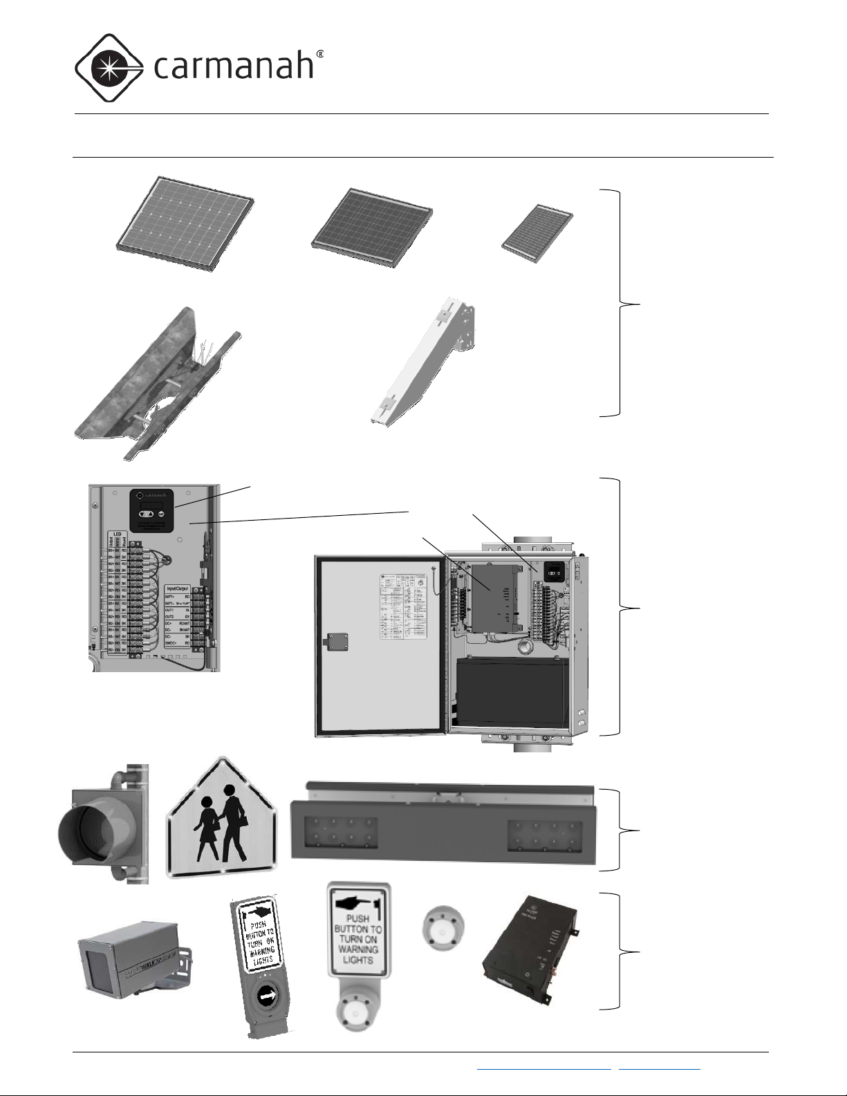
G Series Cabinet
RRFB Light Bars, Circular
Activation Equipment
Three sizes of solar panel
EMS
Time switch (Optional)
Top of Pole
Side of
Onboard User Interface (OBUI)
1.4 System Components
Mount
50W or 80W
(20W , 50W, 80W)
Pole Mount
20W, 50W
or 80W
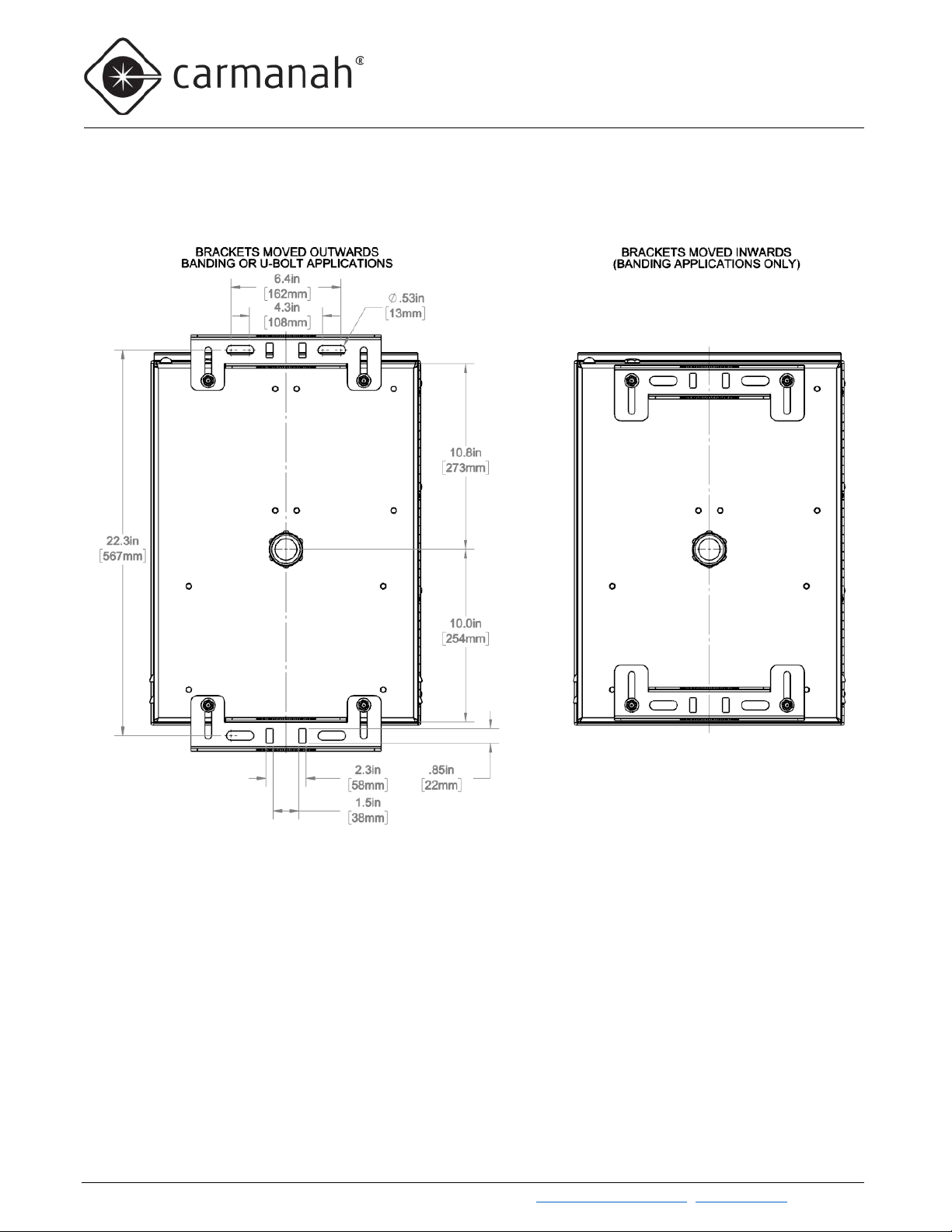
Side and top mounting for
solar panels
Three Battery Sizes
(35Ah, 55Ah, and
100Ah)
Banding and U-Bolt
Mounting Options
Carmanah Technologies Corp. | 250 Bay St, Vi ctoria, BC V9A 3K5, Canada | 1.250.380.0052 | customerservice@carmanah.com | carmanahtraffic.com 6
Beacons, LED Signs
(push buttons, time
switches, sensors, etc.)
G SERIES USER MANUAL
2.0 INTRODUCTION
Models
Applications
LED type(s)
Radio Communication
SC315-G
Pedestrian crosswalks
RRFB or LED Enhanced Signs
Standard
R820-G
Pedestrian crosswalks
Circular beacons or LED Enhanced Signs
Standard
R829-G
School zones, calendar-based
Circular beacons or LED Enhanced Signs
Optional
R247-G
Continuous 24-7 operation
Circular beacons or LED Enhanced Signs
N/A
2.0 Introduction
2.1 About the G Series
The Carmanah G Series products consist of the following models:
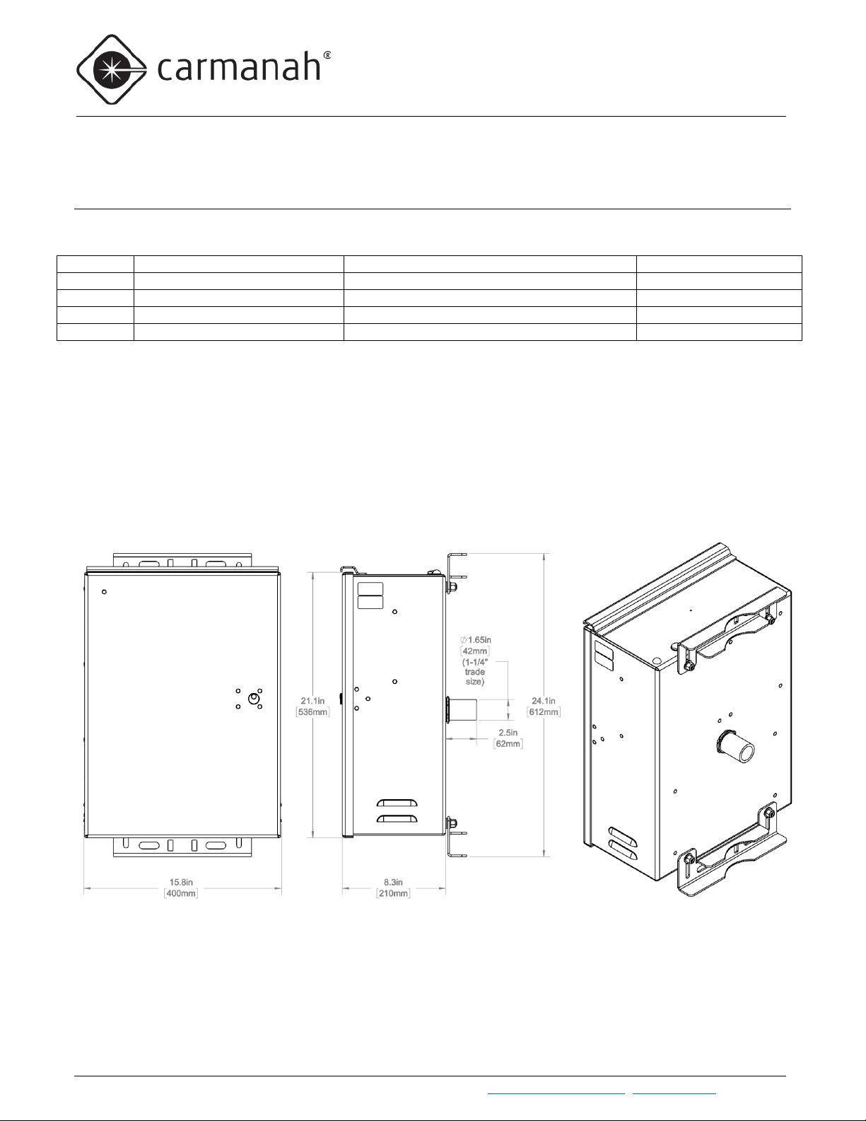
The G Series models are available in solar and AC versions, and all share a common cabinet. Solar models are
available with panel wattages of 20, 50, or 80W, and 12V batteries of 35, 55, or 100Ah capacity. The G Series
can also accommodate third-party devices. While all G Series products share the same user interface on the
Energy Management System (EMS) controller, different models and configurations may differ in behavior, types
of fixture, fixture harnesses, wireless operation, and other aspects. Contact Carmanah if you would like to
repurpose a system from its original model and configuration. Each system will be described in full later in this
user manual.
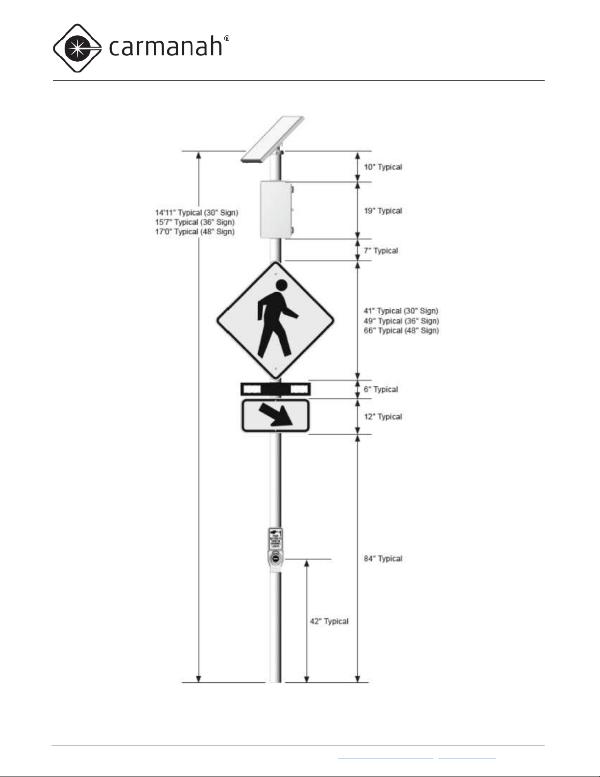
G-Series Cabinet Dimensions
Carmanah Technologies Corp. | 250 Bay St, Vi ctoria, BC V9A 3K5, Canada | 1.250.380.0052 | customerservice@carmanah.com | carmanahtraffic.com 7
G SERIES USER MANUAL
2.0 INTRODUCTION
Carmanah Technologies Corp. | 250 Bay St, Vi ctoria, BC V9A 3K5, Canada | 1.250.380.0052 | customerservice@carmanah.com | carmanahtraffic.com 8
G SERIES USER MANUAL
2.0 INTRODUCTION
Dual EMS Only
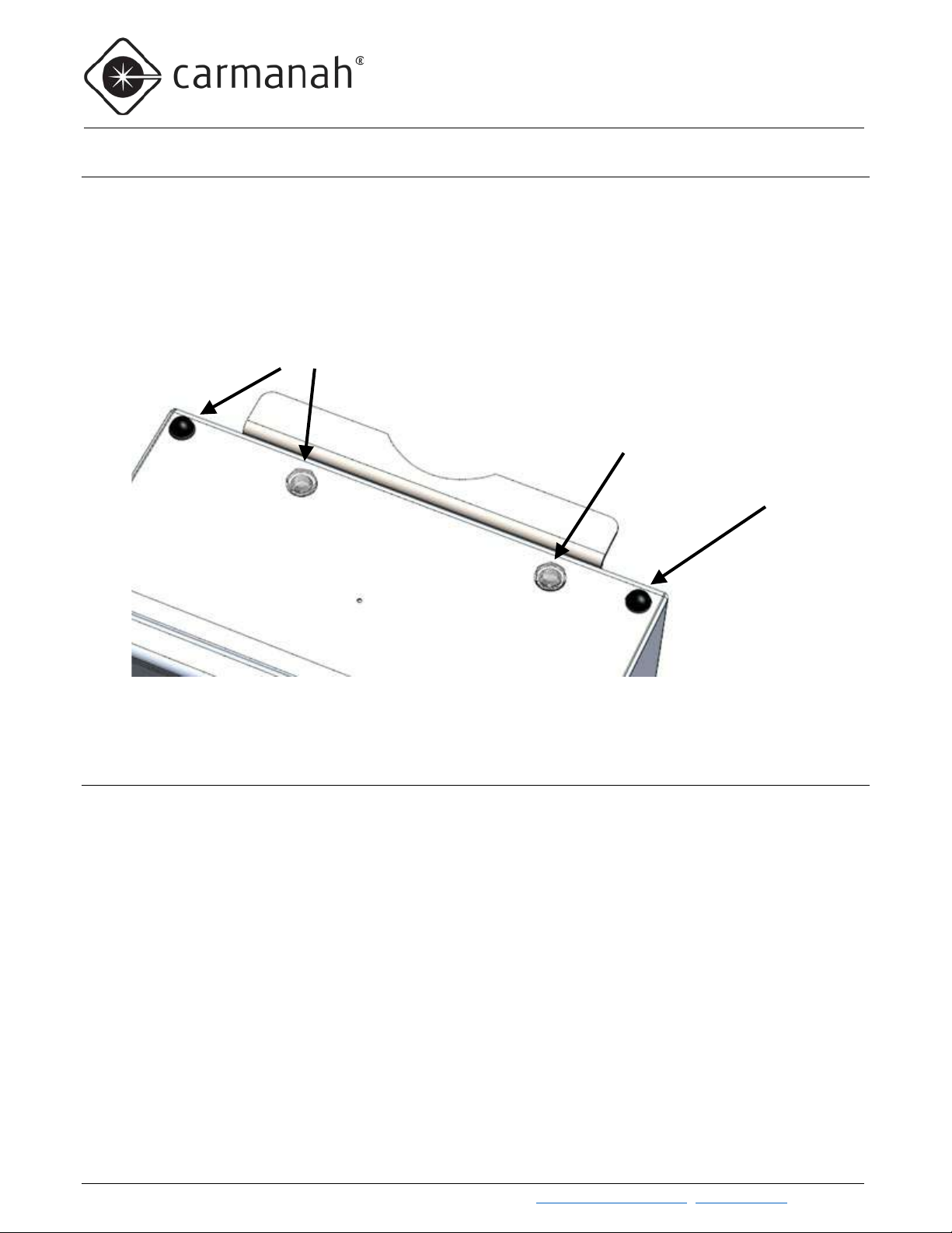
Ambient Brightness Sensor Window
Antenna
2.2 Ambient Brightness Sensor
Each EMS in a G Series is equipped with an ambient brightness sensor on its circuit board. Through a
combination of a light pipe attached to the circuit board and a window on the top of the cabinet, the G Series can
detect ambient light levels outside the cabinet. The G Series uses that data to determine whether it is day or
night, and the amount of AAA (Ambient Auto Adjust) to apply (if enabled). Keep the ambient brightness sensor
clean and clear of debris to ensure accurate light measurements.
Dual EMS G Series systems have a second antenna and ambient brightness sensor window
2.3 Radio Communication
Radio communication between products is standard in R820-G and SC315-G systems and is an option in R829-G
systems. In addition to the G Series, Carmanah also manufactures smaller, self-contained E and F Series
products in which the solar panel, batteries, EMS, and third-party devices reside together in a “solar engine”
enclosure. Wireless communication works seamlessly between products regardless of whether they are E, F, or
G Series. R820 and SC315 systems will also activate each other when a pedestrian pushes the push button.
The radio modules use 2.4GHz DSSS (Direct Sequence Spread Spectrum) with an AES128 encrypted signal and
have been tested with clear line of sight (with no nearby interference or reflected signals) to 1,000 feet (305
meters). Performance is reduced if clean line of sight is not possible.
The G Series products use a low-profile antenna that does not require any special orientation or adjustment and
is immune to vandalism.
Carmanah Technologies Corp. | 250 Bay St, Vi ctoria, BC V9A 3K5, Canada | 1.250.380.0052 | customerservice@carmanah.com | carmanahtraffic.com 9
G SERIES USER MANUAL
2.0 INTRODUCTION
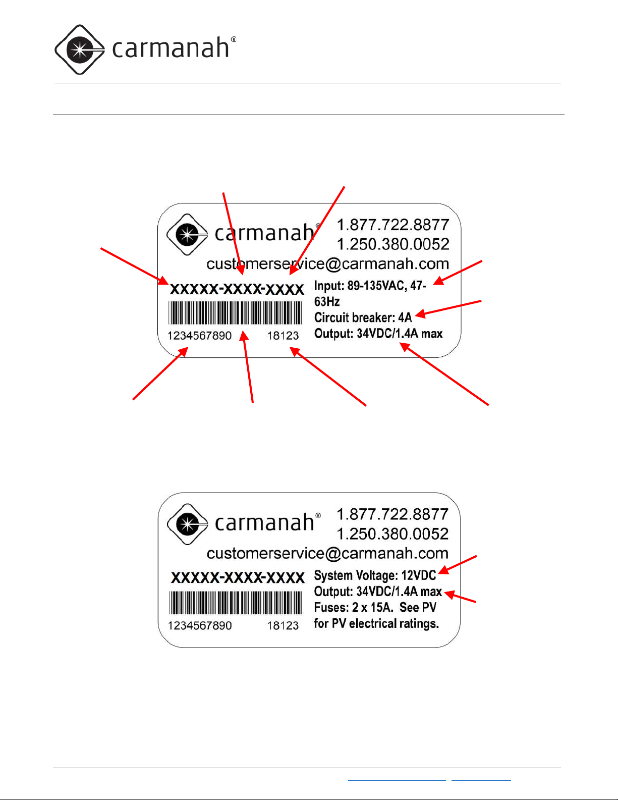
G Series Model
Human-readable
Machine-readable Serial
Manufacture
LED Driver Output Maximums
AC Input
AC Breaker
Flash Pattern
LED Driver Current Setting (mA)
Battery Voltage
(Solar)
Solar Panel and
2.4 Label Explanation
The G Series identification labels appear in two formats—one for solar-powered and one for AC-powered. The
information appearing on the labels is described below:
Power Range
Rating
Serial Number
Number barcode
Date (YYDDD)
Battery Fuse Rating
Carmanah Technologies Corp. | 250 Bay St, Vi ctoria, BC V9A 3K5, Canada | 1.250.380.0052 | customerservice@carmanah.com | carmanahtraffic.com 10
G SERIES USER MANUAL
2.0 INTRODUCTION
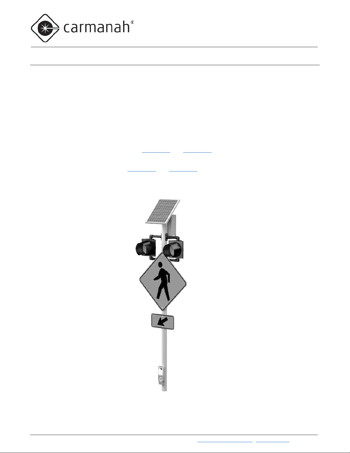
2.5 SC315-G: Pedestrian Crosswalk with RRFB Light Bars
Overview
The SC315-G LED Rectangular Rapid Flashing Beacon (RRFB) products are ideal for uncontrolled pedestrianactivated crosswalk applications. Multiple SC315-G units can be combined to create a complete crosswalk set.
Each SC315-G is radio-controlled, and each synchronizes flashing with other SC315-Gs and R920-E/Fs or
advance R820-E/F/Gs. The system will flash for a pre-set duration (field-adjustable) upon activation of the push
button. Spread-spectrum wireless communications activates the light bars across the street or in advance of the
crossing. A typical installation consists of two pairs of light bars, with each pair mounted on poles at opposite ends
of the crosswalk. Wireless communication between units means that SC315-Gs require no trenching of cables
across the roadway.
Details on RRFB light bars can be found in Section 2.7 and Section 4.1
As an alternative to light bars, SC315-G systems can be configured with LED Enhanced Signs. Details on LED
Enhanced Signs can be found in Section 2.9 and Section 4.3
.
.
Typical SC315-G Configurations
Carmanah Technologies Corp. | 250 Bay St, Vi ctoria, BC V9A 3K5, Canada | 1.250.380.0052 | customerservice@carmanah.com | carmanahtraffic.com 11
G SERIES USER MANUAL
2.0 INTRODUCTION
Typical SC315-G Configurations, cont’d
Carmanah Technologies Corp. | 250 Bay St, Vi ctoria, BC V9A 3K5, Canada | 1.250.380.0052 | customerservice@carmanah.com | carmanahtraffic.com 12
G SERIES USER MANUAL
2.0 INTRODUCTION
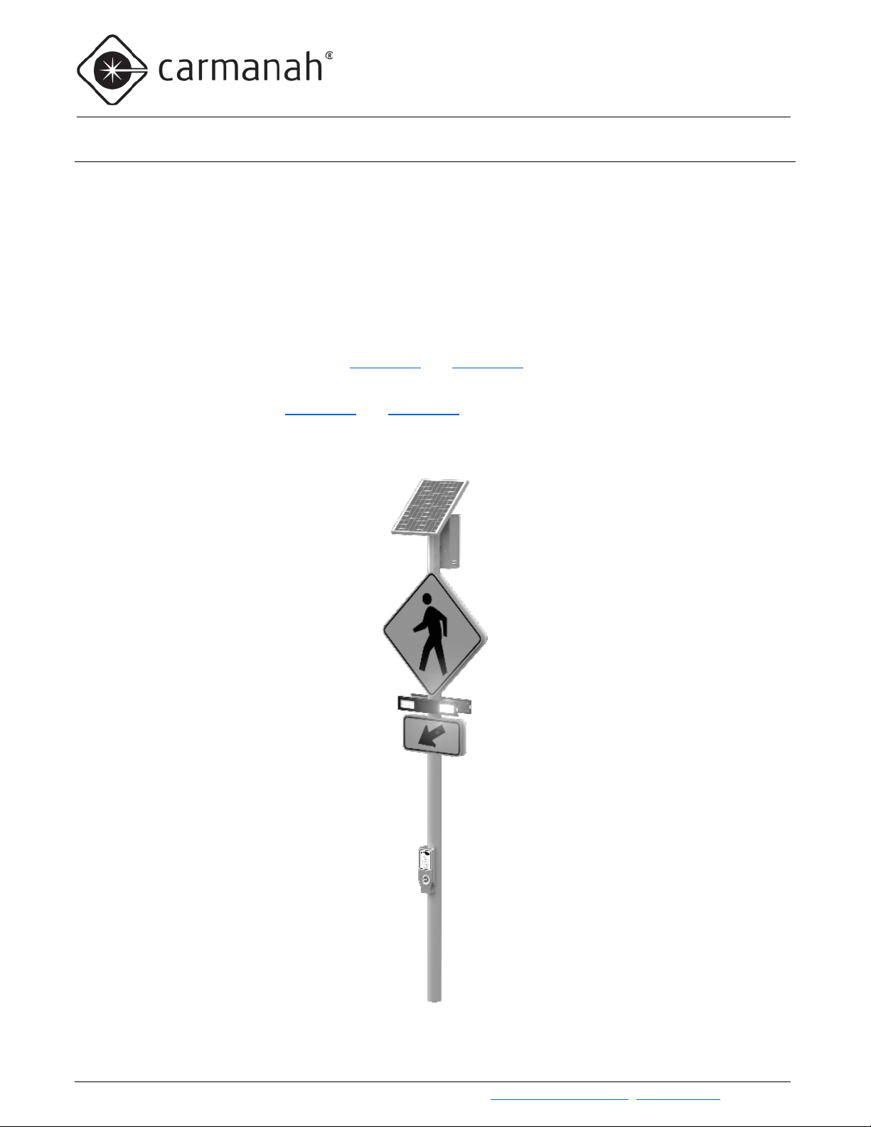
2.6 R820-G: Pedestrian Crosswalk with Circular Beacons
Overview
Multiple R820-G units can be combined to create a complete crosswalk set. Each R820-G is radio-controlled, and
each synchronizes flashing with other R820-Gs in the crosswalk set. The system will flash for a pre-set fieldadjustable duration upon activation of the push button. Wireless communication activates the beacons across the
street or in advance of the crossing. A typical installation consists of two pairs of flashing circular beacons, with
each pair mounted on poles at opposite ends of the crosswalk. Wireless communication between units means
that R820-Gs require no trenching of cables across the roadway.
R820-Gs can also be wirelessly controlled by an R829-G master controller. The R820-Gs and R829-G operate
together based on the schedule programmed into the R829-G’s internal calendar.
Details on circular beacons can be found in Section 2.8 and Section 4.2
As an alternative to circular beacons, R820-G systems can be configured with LED Enhanced Signs. Details on
LED Enhanced Signs can be found in Section 2.9 and Section 4.3
.
.
Typical R820-G Configuration
Carmanah Technologies Corp. | 250 Bay St, Vi ctoria, BC V9A 3K5, Canada | 1.250.380.0052 | customerservice@carmanah.com | carmanahtraffic.com 13
G SERIES USER MANUAL
2.0 INTRODUCTION
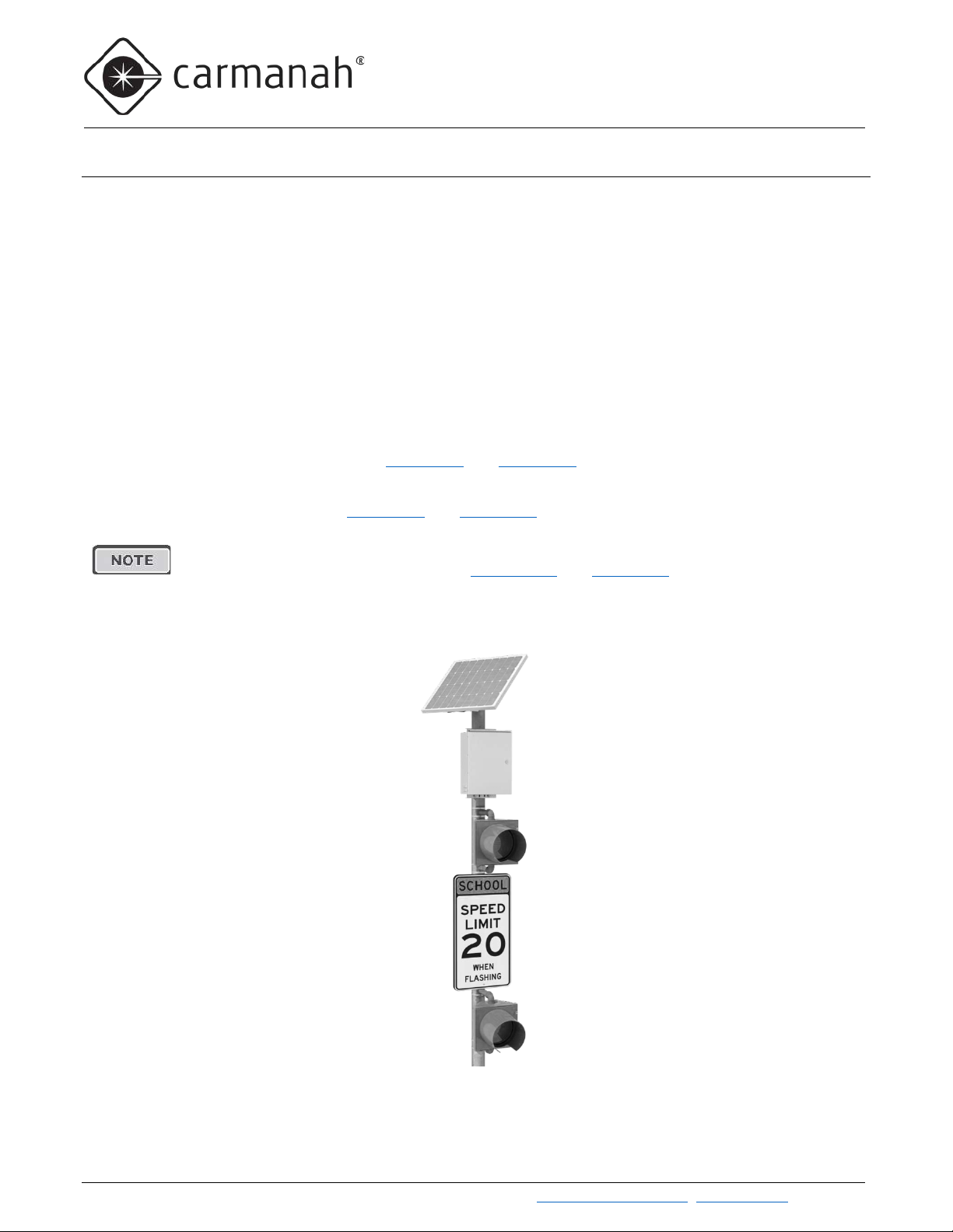
2.7 R829-G: School Zone Flashing Beacon
Overview
The R829-G School Zone Flashing Beacon systems operate on a programmable calendar used to set the days
and times when the beacon(s) will flash. There are four ways that an R829-G system can follow a calendar
schedule:
1) A non-wireless R829-G can operate on its own, automatically flashing based on the schedule
programmed into its internal calendar.
2) A non-wireless R829-G can also be turned on and off through a hard-wired switch. This switching function
can be provided by an override box, a third-part time switch, or both.
3) A wireless R829-G can operate as the master controller in a group of wireless Carmanah E, F, or G
Series traffic products.
4) Other Carmanah E, F, or G Series products respond to commands from a wireless R829-E/F/G master
controller system and operate according to the master’s calendar schedule.
Details on circular beacons can be found in Section 2.8 and Section 4.2
As an alternative to circular beacons, R829-G systems can be configured with LED Enhanced Signs. Details on
LED Enhanced Signs can be found in Section 2.9 and Section 4.3
F and G Series products feature optional time switch kits that allow various third-party products to
be mounted within the solar engine. See Section 2.10 and Section 5.0 for details.
.
.
Typical R829 Configuration
Carmanah Technologies Corp. | 250 Bay St, Vi ctoria, BC V9A 3K5, Canada | 1.250.380.0052 | customerservice@carmanah.com | carmanahtraffic.com 14

G SERIES USER MANUAL
2.0 INTRODUCTION
Ensure you obtain the latest copy of the calendar software (Version 1.2.0 as of November 2018).
See Section 5.1 for more information about related accessory calendar upload / override
Internal Calendar (standard on R829-G, optional on other systems)
The R829-G is equipped with an internal calendar that is programmed via USB to automatically activate and
deactivate school zone flashers on a user-defined schedule of up to 512 days. The calendar is programmed using
an intuitive Microsoft Windows-based graphical user interface. Once the program is established for one system,
the settings can be uploaded to other R829-G units onsite with a laptop PC. A USB cable is part of the calendar
programming kit and is provided coiled up inside the R829-G cabinet.
Eight different day schedule types can be defined (including OFF all day). Each day type can be configured for up
to eight ON periods of adjustable duration. Refer to the support document “R829 School Zone Calendar
Configuration Instructions” for additional information and complete programming instructions.
Older versions of the calendar software will not operate correctly with the newest version of traffic
firmware. Minimum Windows 7 operating system is required (32-bit or 64-bit). The software can
be obtained by contacting Carmanah Traffic Sales. The software is also included on a USB
memory stick in the calendar software programming kit, which also includes a 32-foot active
USB extension harness which can be used to program a system’s calendar from a vehicle.
switch kit.
2.8 R247-G: 24-Hour Flashing Beacon
Overview
The R247-G Flashing Beacon flashes continuously 24 hours per day 7 days per week and is used for a wide
range of warning applications such as stop lights and low bridges.
The R247-G can be turned off when required using the optional Override Box kit, see Section 5.1
Details on circular beacons can be found in Section 2.8 and Section 4.2.
As an alternative to circular beacons, R247-G systems can be configured with LED Enhanced Signs. Details on
LED Enhanced Signs can be found in Section 2.9 and Section 4.3
.
Typical R247-G Configuration
.
Carmanah Technologies Corp. | 250 Bay St, Vi ctoria, BC V9A 3K5, Canada | 1.250.380.0052 | customerservice@carmanah.com | carmanahtraffic.com 15
G SERIES USER MANUAL
2.0 INTRODUCTION
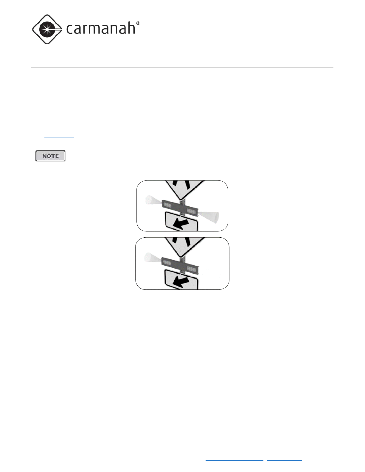
Dual Confirmation Light
Single Confirmation Light
2.9 RRFB Light Bars: Overview
Standard G Series products support up to four RRFB light bar fixtures, or up to eight for dual EMS systems. The
FHWA Interim Approval 21 March 20
standard for photometrics. Each light bar consists of a left and right module, with each module having eight LEDs
connected in series. In addition, each end of a light bar has a single “confirmation” LED that pedestrians can see
from across the street and know with confidence that the light bars are flashing in response to their pressing of
the pedestrian push button. Opaque adhesive covers are included to optionally cover the confirmation LED if
desired.
See Section 4.1
for information on installing and aiming light bars.
When programming intensity for ITE-compliant RRFBs, minimum current settings must be
applied, (see Flash Pattern and Intensity in Section 6.1). Contact Carmanah for guidance.
– No Opaque Cover
th
, 2018 defines the flash pattern of the RRFB and specifies the J595
– Using Opaque Cover
Carmanah Technologies Corp. | 250 Bay St, Vi ctoria, BC V9A 3K5, Canada | 1.250.380.0052 | customerservice@carmanah.com | carmanahtraffic.com 16
G SERIES USER MANUAL
2.0 INTRODUCTION
2.10 Circular Beacons: Overview
Standard G Series products support up to eight circular beacons, or up to 16 for dual EMS systems. The beacons
are industry-standard equipment and comply with MUTCD and ITE flash patterns, color, beam shape, and
intensity. Beacon wiring is provided with a convenient terminal strip inside the signal head for easy wire
connection.
LED loads driven from one EMS must have the same operating voltage. Do not mix different
sizes, colors, or types of LED loads connected to the same EMS. Use a dual-EMS G Series
system to drive two different LED loads.
If powering three, five, or seven LED loads from a single EMS, use a “Unison” flash pattern to
avoid current imbalance and ensure all loads receive the same amount of current while flashing
and therefore produce the same brightness.
All Carmanah traffic products use a constant-current LED output circuit. Not all traffic beacons
are compatible with this output. Please contact Carmanah for additional information and guidance
when adding or replacing beacons or other hardware.
When programming intensity for ITE-compliant circular beacons, minimum current settings
must be applied (see Flash Pattern and Intensity
See Section 4.2 for information on installing circular beacons.
in Section 6.1). Contact Carmanah for guidance.
Carmanah Technologies Corp. | 250 Bay St, Vi ctoria, BC V9A 3K5, Canada | 1.250.380.0052 | customerservice@carmanah.com | carmanahtraffic.com 17
G SERIES USER MANUAL
2.0 INTRODUCTION
LED loads driven from one EMS must have the same operating voltage. Do not mix different
If powering three, five, or seven LED loads from a single EMS, use a “Unison” flash pattern to
All Carmanah traffic products use a constant-current LED output circuit. Not all traffic beacons
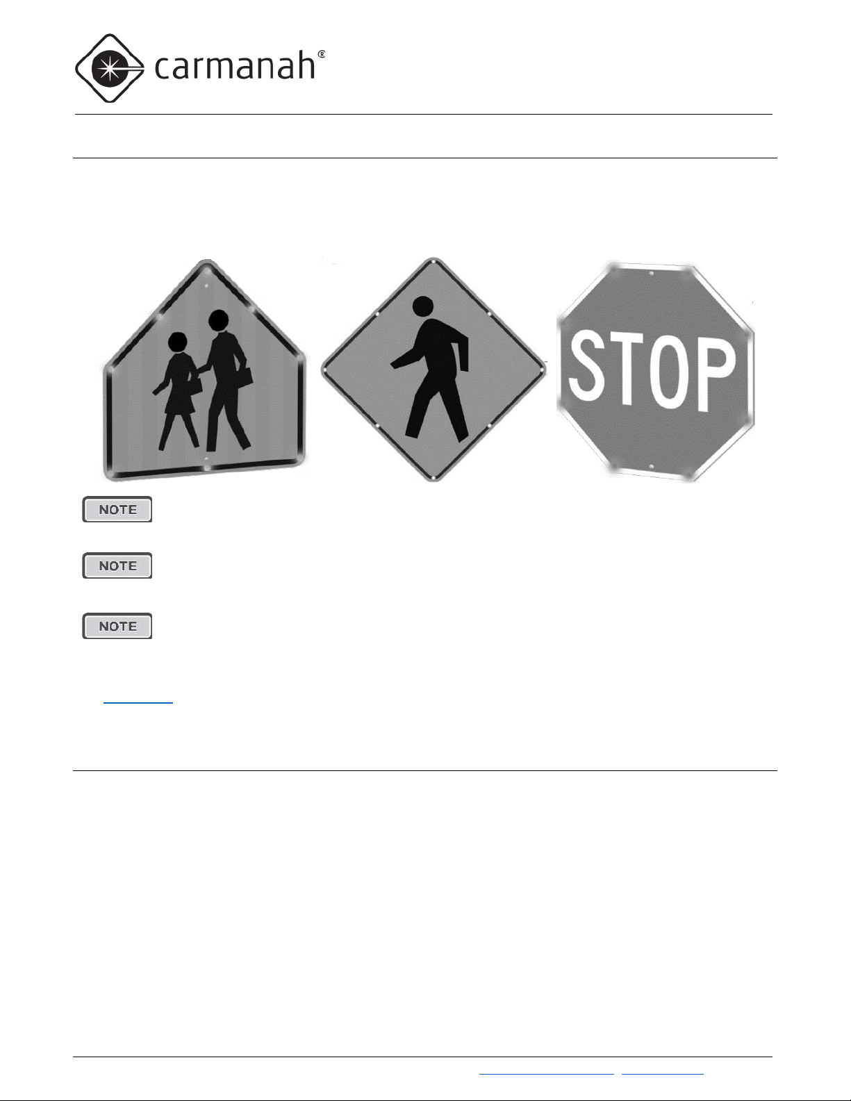
2.11 LED Enhanced Signs: Overview
In addition to RRFB light bars and circular beacons, G Series products can power LED Enhanced Signs. LED
Enhanced Signs are available in a variety of formats including stop and pedestrian crosswalk signage. LED
Enhanced Signs are electrically connected and driven directly by the EMS like other traffic fixtures. LED
Enhanced Signs have the same degree of intensity and flash pattern control as other fixtures.
sizes, colors, or types of LED loads connected to the same EMS. Use a dual-EMS G Series
system to drive two different LED loads.
avoid current imbalance and ensure all loads receive the same amount of current while flashing
and therefore produce the same brightness.
are compatible with this output. Please contact Carmanah for additional information and guidance
when adding or replacing beacons or other hardware.
See Section 4.3 for information on installing LED Enhanced Signs.
2.12 Third-Party Devices: Overview
A third-party device (3PD) is non-Carmanah equipment that interacts with the system in one or more ways:
• The G Series provides a status signal to 3PD (e.g. Digital Output signals when fixtures are flashing, allowing
3PD equipment such as overhead lighting to activate)
• The 3PD provides control signal to G Series (e.g. time switch, passive pedestrian detection, water level
detectors)
• The G Series only provides power to 3PD (e.g. radio/communications)
The G Series is available with several optional 3PD kits which allow the installation of the 3PD within the G Series
cabinet:
• The G Series RTC/IDC time switch kit option allows the installation of an RTC or IDC time switch and
includes a mounting plate, switch mounting hardware, and a prewired harness with a connector that plugs into
Carmanah Technologies Corp. | 250 Bay St, Vi ctoria, BC V9A 3K5, Canada | 1.250.380.0052 | customerservice@carmanah.com | carmanahtraffic.com 18
G SERIES USER MANUAL
2.0 INTRODUCTION
Contact Carmanah for additional support in connecting and configuring the above the devices or
other third-party devices.
the time switch. (Time switch not included.) For installation information see Section 5.2, Section 5.3 and
Section 5.5.
• The G Series Applied Information modem kit option allows the installation of an AI time switch and cellular
modem. It includes mounting hardware, an antenna, and a prewired, connectorized harness to interface
between the G Series and the AI time switch and modem. (AI time switch/modem not included). For
installation information see Section 5.4 and Section 5.5
• The G Series Relay kit for digital output, AC option comes with a 10A AC relay prewired to the G Series
EMS. For installation information see Section 5.6
• The G Series Relay kit for digital output, DC option comes with a 10A DC relay prewired to the G Series
EMS. For installation information see Section 5.7
• The G Series Polara XAV controller kit option includes the Polara XAV controller prewired for the Polara
XAV2E audible push button. Push button station harness length options are 16ft, 36ft, or 75ft. For installation
information, see Section 5.8
• The G Series Campbell Guardian kit option includes a push button harness (16ft, 36ft, or 75ft) prewired to
the G Series EMS, along with the Guardian audible push button and an associated sign. For installation
information, see Section 5.9
.
.
.
.
.
Carmanah Technologies Corp. | 250 Bay St, Vi ctoria, BC V9A 3K5, Canada | 1.250.380.0052 | customerservice@carmanah.com | carmanahtraffic.com 19
G SERIES USER MANUAL
3.0 SOLAR PANEL AND CABINET INSTALLATION
Ensure the installation location has an unobstructed view of the sun’s path. Obstructions
simulations for your site.
3.0 Solar Panel and Cabinet Installation
such as trees or buildings could significantly reduce the amount of sunlight on the solar
panel. Shade analysis is highly recommended to understand how shadows will change
according to the time of year. Contact Carmanah for a detailed examination and solar
3.1 Tools and Materials Required
The following tools and materials may be required to mount your Carmanah flashing beacon depending on the
model and configuration:
1. Imperial socket set
2. Crescent wrench
3. Tap set (some configurations)
4. Imperial Allen-Wrench set
5. Fish tape
6. Level
7. Compass (or smart phone compass app)
8. Drill and drill bits
9. Fine-tip felt marker
10. Multi-bit screwdriver
11. Pelco Roger-Wrench (some configurations)
12. Hook spanner wrench, 1-1/2” trade size
(some configurations)
13. Ladder or lift device
14. Lithium grease
3.2 Pole Preparation
1. Mark positions of flashing beacons, cabinet, and side of pole mount (if required) on pole.
2. Drill 1-3/4” dia. hole at desired position of cabinet nipple.
3. Drill cable exit/entry points for the flashing beacons and side of pole solar panel mount (if used).
4. Fish solar harness between top of pole (or side of pole mount hole) to cabinet nipple hole.
5. Fish flashing beacon harnesses between cabinet nipple hole and flashing beacon holes.
3.3 Solar Panel Installation
There are two options for mounting the G Series solar panel:
• Top of Pole – Fixed at 45 degrees angle with built-in bird deterrent
• Side of Pole – Adjustable inclination angle. Set it for 45 degrees unless Carmanah has conducted solar
simulations that resulted in a recommendation for a different panel inclination angle.
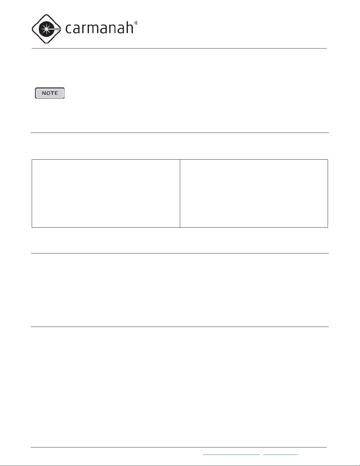
Top of Pole Solar Panel Installation
1. Attach tenon clamp brackets to 45-degree mount. Use ¼” bolts and ¼” locknuts supplied. Tighten nuts
and bolts securely.
Carmanah Technologies Corp. | 250 Bay St, Vi ctoria, BC V9A 3K5, Canada | 1.250.380.0052 | customerservice@carmanah.com | carmanahtraffic.com 20
G SERIES USER MANUAL
3.0 SOLAR PANEL AND CABINET INSTALLATION
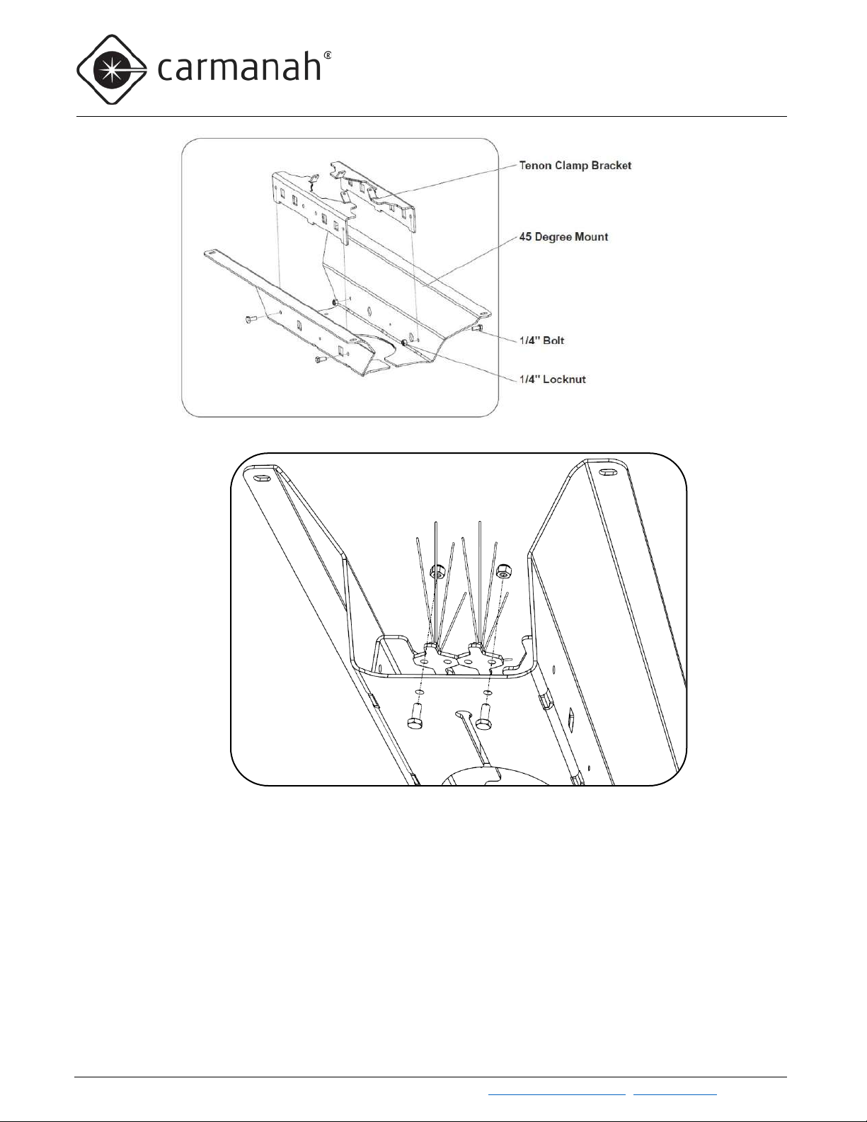
2. If needed, install bird deterrent spikes with ¼” bolts and lock nuts as shown.
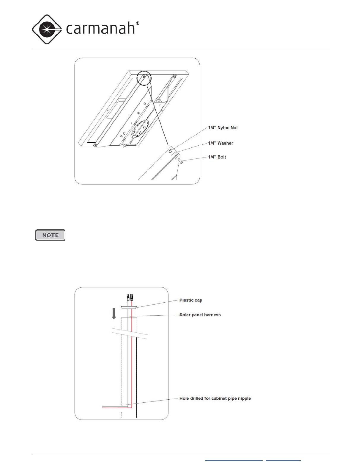
3. Attach solar panel (50W, 80W , or 170W) to the 45-degree mount. Use bolts, washers, and locknuts that
were supplied. Tighten nuts and bolts loosely—do not fully tighten at this stage.
Carmanah Technologies Corp. | 250 Bay St, Vi ctoria, BC V9A 3K5, Canada | 1.250.380.0052 | customerservice@carmanah.com | carmanahtraffic.com 21
G SERIES USER MANUAL
3.0 SOLAR PANEL AND CABINET INSTALLATION
Your system includes a cap for the open top of the pole. The cap prevents debris from entering
4. Drill 1-3/4” dia. hole in the pole in the desired cabinet location.
the pole. There are plastic and metal versions of the cap:
• The plastic cap is inserted into the top of the pole prior to attaching the solar mount bracket.
• The metal cap is used by Miami-Dade County and is attached to the solar panel mounting
bracket before the solar panel is mounted on the pole. Instructions are provided at the end of
this section.
PLASTIC CAP INSTALLATION (FOR LOCATIONS OTHER THAN MIAMI DADE COUNTY):
5. Fish solar panel harness through pole and plastic cap as shown, with black connectors at top.
Carmanah Technologies Corp. | 250 Bay St, Vi ctoria, BC V9A 3K5, Canada | 1.250.380.0052 | customerservice@carmanah.com | carmanahtraffic.com 22
G SERIES USER MANUAL
3.0 SOLAR PANEL AND CABINET INSTALLATION
METAL CAP INSTRUCTIONS (MIAMI DADE COUNTY ONLY):
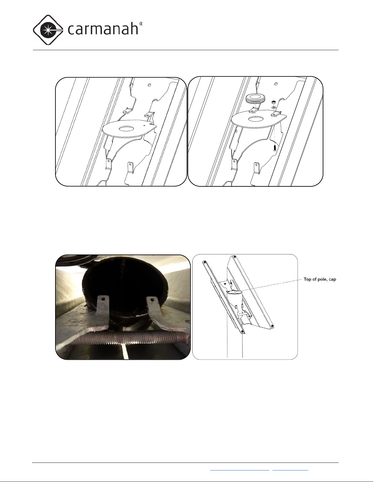
6. Install the metal cap, grommet, and hardware onto the bracket as shown.
7. Lower solar panel and top of pole bracket down onto pole. For metal caps, route solar cables up through
grommet in cap. Make sure panel mount sits securely on top of pole cap as shown below (solar panel not
shown to allow visibility of pole top). When setting top of pole mount on pole, ensure two tabs are resting
on lip of pole cap. Also, look underneath solar panel to ensure wiring is not pinched.
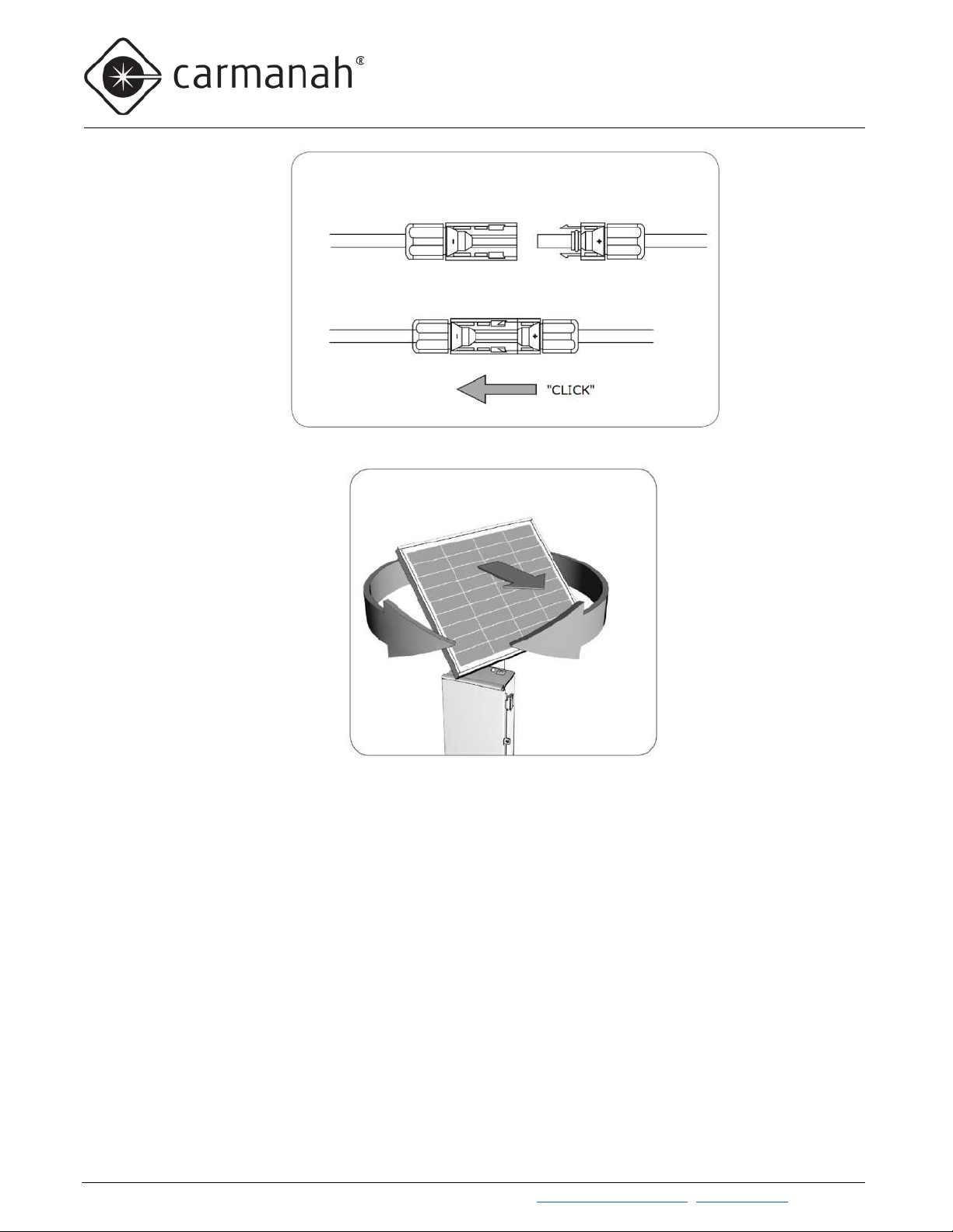
8. Mate black MC4 connectors from solar panel to those from solar harness. A click noise indicates they are
fully mated. Tuck excess harness length down into pole or coil up excess harness and cable tie securely,
if desired.
Carmanah Technologies Corp. | 250 Bay St, Vi ctoria, BC V9A 3K5, Canada | 1.250.380.0052 | customerservice@carmanah.com | carmanahtraffic.com 23
G SERIES USER MANUAL
3.0 SOLAR PANEL AND CABINET INSTALLATION
9. Ensure solar panel is facing equator (pointing south if you are in the Northern Hemisphere).
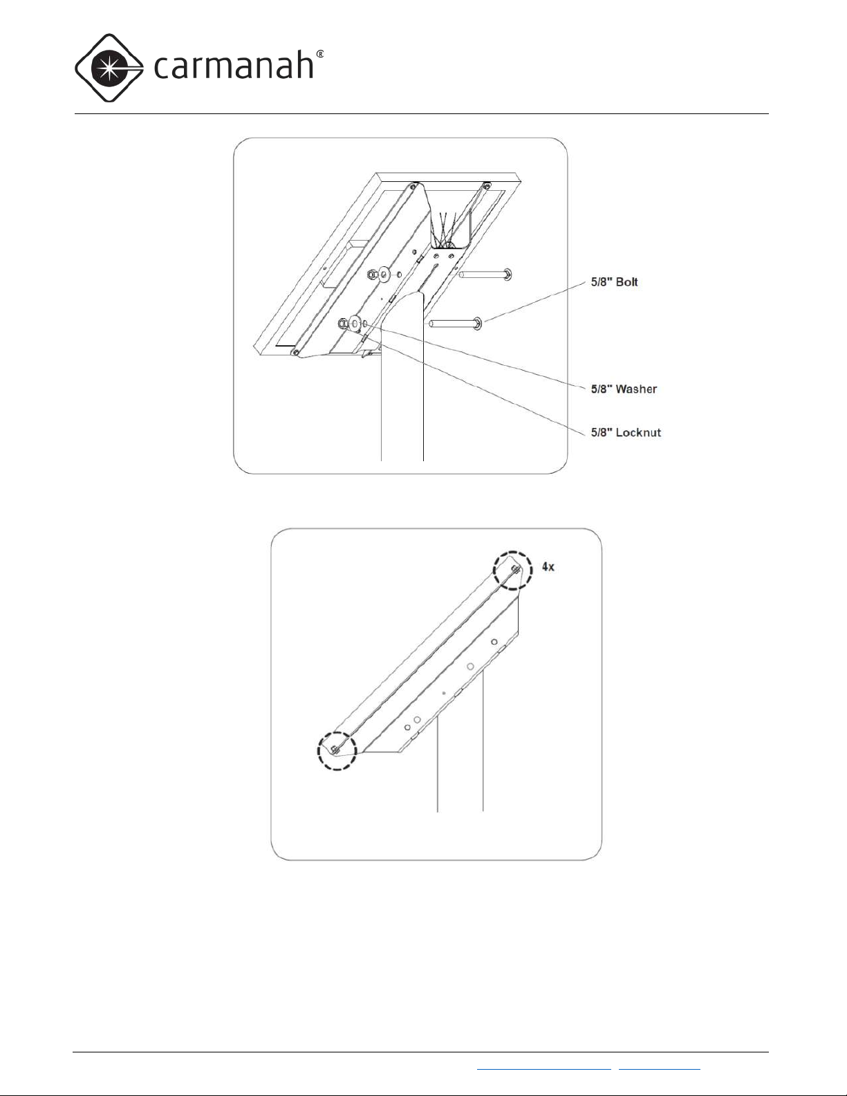
10. Install and tighten 5/8” bolts, washers, and nuts to secure top of pole bracket to pole as shown.
Carmanah Technologies Corp. | 250 Bay St, Vi ctoria, BC V9A 3K5, Canada | 1.250.380.0052 | customerservice@carmanah.com | carmanahtraffic.com 24
G SERIES USER MANUAL
3.0 SOLAR PANEL AND CABINET INSTALLATION
11. Tighten four nuts and bolts securing solar panel to bracket.
Carmanah Technologies Corp. | 250 Bay St, Vi ctoria, BC V9A 3K5, Canada | 1.250.380.0052 | customerservice@carmanah.com | carmanahtraffic.com 25
 Loading...