

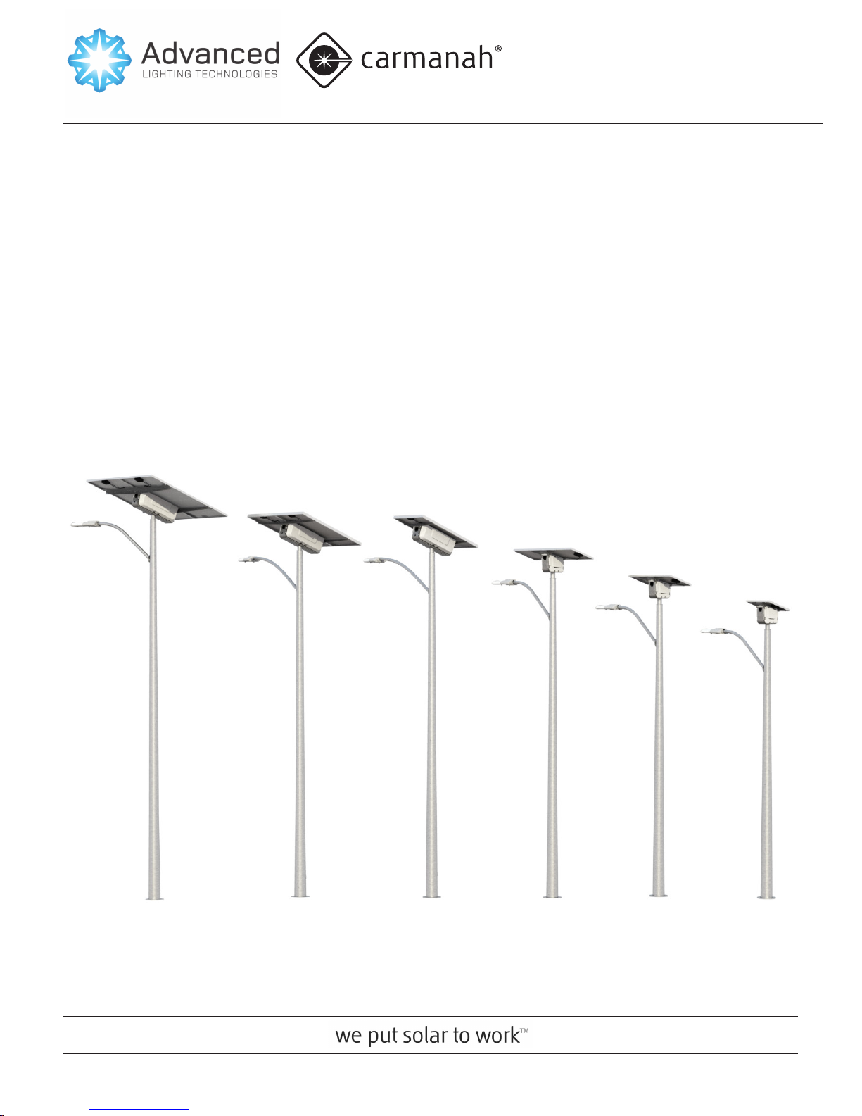
EG-SERIES
USER MANUAL • MANUAL DEL USUARIO • MANUEL DE L'UTILISATEUR
Model • Modelo • Modèle
EG40/EG80/EG145/EG320/
EG340/EG500
EG-SERIES USER MANUAL
WARNING
CAUTION
NOTE
WARNING
WARNINGS ANd PREcAUtIoNS
Warnings and Precautions
The following symbols indicate important safety
warnings and precautions throughout this manual.
They are dened as follows:
WARNING indicates that serious
bodily harm or death may result
from failure to adhere to the
precautions.
CAUTION indicates that damage
to equipment may result if the
instructions are not followed.
NOTE suggests optimal conditions
under which the equipment will
operate effectively and safely, or
provides additional information to
the reader.
Warranty Disclaimer
This manual will familiarize you with the features and
operation standards of Carmanah's EG-series lights.
Failure to comply with the use, storage, maintenance,
installation or placement instructions detailed in this
manual could void the applicable user warranty.
Standards
Perform all installation, wiring and maintenance in
conformance with local building and electrical codes.
Adherence to the National Electrical Code (NEC)
is mandatory. Non-adherence to code may void the
warranty.
Safety and Usage Precautions
Batteries are shipped fully-charged.
Use extreme caution when handling
the batteries as they are capable
of generating hazardous shortcircuit currents. Remove all jewelry
(bracelets, metal-strap watches,
etc.) before attempting to handle the
batteries.
Solar modules produce DC electricity when exposed to light and
can, therefore, produce an electrical shock or burn. To render solar
modules inoperative, remove
them from sunlight, or fully cover
their front surface with an opaque
material.
Before lifting any heavy or bulky
equipment, ensure that the load is
secured so that moving parts do
not shift and it can be lifted as far
as needed without back strain or
loss of grip. Installation may require
more than one person.
Until the system is ready for startup,
keep the battery fuse out of the fuse
holder. Ensure the equipment is
not powered during installation and
wiring of the system.
Re-check all completed wiring for
proper polarity prior to energizing
the system.
On Start-Up, follow the procedures described in the “Testing the
system” section of this document.
2
© 2012, Carmanah Technologies Corporation. 63966_EG_Series_UserManual_RevB

EG-SERIES USER MANUAL
NOTE
tAbLE of coNtENtS
Changes or modications to
Carmanah equipment not expressly
approved by Carmanah could void
the user's authority to operate the
equipment.
Table of Contents
Warnings and Precautions ......................................2
Warranty Disclaimer ...............................................2
Standards ..............................................................2
Safety and Usage Precautions .............................. 2
Introduction ...............................................................4
Features and Functionality ....................................4
Installation .................................................................5
EG-Series Programmer ............................................6
Setting brightness and Programming ....................7
Installing the current-setting resistor ......................7
Programming using the EG-series Programmer .... 7
Testing the system ...................................................8
EMS Indicator Lights ...............................................9
Maintenance & Product Care.................................10
Fuse Replacement ............................................... 10
Battery Replacement ........................................... 10
Troubleshooting ..................................................... 11
Specications .........................................................13
Warranty .................................................................. 14
© 2012, Carmanah Technologies Corporation. 63966_EG_Series_UserManual_RevB
3
EG-SERIES USER MANUAL
INtRodUctIoN
Introduction
EG-series solar LED lighting products are ideal for
street, parking lot and general site lighting.
Features and Functionality
The EG-series product family includes the EG40,
EG80, EG145 and larger EG320, EG340 and EG500
models. The following components make up these
products:
• EG-Series Solar Engine, consisting of:
•Energy Mangement System (EMS)
•Chassis assembly
•Solar panel(s)
•Solar panel rails (2)
•Batteries
• LED xture(s)
• EG-series programmer
The solar panels and EMS work together to charge
the batteries during the day. At night, the EMS
controls the ow of power from the batteries to the
LED xture(s).
4
© 2012, Carmanah Technologies Corporation. 63966_EG_Series_UserManual_RevB

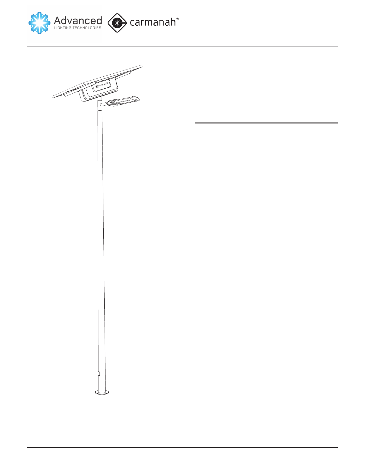
Installation
For details on the assembly and installation of EG-series
products, please see the appropriate Installation Guide.
A summary of the assembly and installation process is
given below:
• EG-series solar engine is assembled and installed onto
the pole using a crane and bucket truck
• The xture wires are routed and the xture installed
• The unit is programmed and tested
Accessory installation kits are available and recommended
to facilitate system installation. The kits consists of lifting
straps, shackles, and a solar panel connector disassembly
tool. The part numbers are:
• EG320 Install kit - Carmanah part # 65937
• EG340 Install kit - Carmanah part # 65938
• EG500 Install kit - Carmanah part # 65938
EG-SERIES USER MANUAL
INStALLAtIoN
© 2012, Carmanah Technologies Corporation. 63966_EG_Series_UserManual_RevB
5

EG-SERIES USER MANUAL
NOTE
EG 300 PRoGRAMMER
EG-Series Programmer
The programmer is used to program the EMS with
the correct operating prole for your application.
The programmer is also used to test the EG-series
system to conrm correct operation. The programmer
is powered by two AA batteries (not included), and
communicates with the EG-series EMS using two-way
infrared signals.
The programmer has two buttons: Send and Test. The
Send button is used to upload the operating prole
(parameters) to the EG-series EMS, while the Test
button is used to test that the EG-series system is
operating correctly.
The 12 knobs and switches on the programmer
come pre-congured with the correct settings for your
application. If the knobs or switches get moved accidentally, return them to the positions indicated by the
faceplate label.
The programmer has indicator lights and a beeper
to convey status to the user. The following table
summarizes the meanings of the lights and the
beeper:
Feedback Status
Three short beeps & green OK
light ~5s after pressing/holding
Send button
One long beep & red Error
light ~5s after pressing/holding
Send button
One short beep after pressing/
holding Test button
One long beep & red Error light
immediately after pressing Test
or Send button
Programming successful
Programming not successful
Test command transmitted
Replace 2 X AA batteries in
programmer
The EG-series uses two-way
communication between the
programmer and EMS. Therefore
each EG-series EMS must be
programmed one at a time.
Problems arise when more than
one EMS is in range during
programming.
6
© 2012, Carmanah Technologies Corporation. 63966_EG_Series_UserManual_RevB

EG-SERIES USER MANUAL
SEttING bRIGhtNESS ANd PRoGRAMMING
Setting brightness and
Programming
As part of the installation process, the EG-series is congured with a xture current, which sets the base xture
brightness, and an operating prole, which controls xture
on/off times and, for some proles, xture dimming.
The current setting for every EG-series system is carefully
chosen to work together with the operating prole without
consuming more than the available solar energy in the
installation location.
The EG-series is congured in two steps: 1) installing the
xture current-setting resistor, and 2) programming the
EMS using the EG-series Programmer.
Installing the current-setting resistor
Programming using the EG-Series
Programmer
The EG-series Programmer is used to upload
(program) the operating prole into the EG-series
EMS. This should be done during installation of the
system (see EG-series Installation Guide for details).
Follow these steps to program the EMS:
• Make sure the knobs and switches are positioned
as indicated by the label on the EG-series
programmer.
• Point the programmer at the infrared transmitter/
receiver on the EG-series EMS.
• Press and hold the Send button on the
programmer.
• Continue to hold down the Send button until the
programmer beeps.
• If the Programmer beeps three times and the green
OK light on the programmer lights, programming
was successful.
• If the Programmer emits one long beep and the red
Error light on the programmer lights, programming
was not successful.
The amount of current going to the LED xture(s) is determined by the current setting resistor, which is installed in a
sealed holder in the EG-series EMS wiring harness. When
no resistor is installed, the xture current reverts to the
lowest possible setting.
The current-setting resistor should be inserted into the
holder during the installation of the EG-series system (see
EG-series Installation Guide for details). If this step was
forgotten during installation, the current-setting resistor can
be installed by:
EG320/340/500: pulling the resistor holder out through the
access hole under the EMS, removing the holder cap, and
inserting the resistor.
EG40/80/145: tilting the solar panel forward, removing the
holding cap, and inserting the resistor.
The current-setting resistor can be inserted into the holder
in any orientation. Make sure it is seated rmly in the
electrical contacts.
© 2012, Carmanah Technologies Corporation. 63966_EG_Series_UserManual_RevB
If programming was not successful, try getting closer
to the EG-series EMS and make sure you accurately aim the programmer at the infrared transmitter/receiver on the EMS while pressing and holding
the Send button. Programming can be done from
the ground, but may not work during the middle of
the day, when the strong infrared radiation from the
sun interferes with communications between the
Programmer and EMS.
7

EG-SERIES USER MANUAL
tEStING thE SyStEM
Testing the system
The EG-series Programmer can be used to test the
EG-series system. To test the system:
• Point the programmer at the IR transmitter/receiver
on the EG-series EMS.
• Press and hold the Test button on the programmer
until it beeps once.
• The LED xture should turn on briey to indicate
that the system is operating properly.
The test command may not be received by the
EG-series EMS on bright, sunny days. Try getting
closer to the EMS, or try testing later in the day when
the sunlight won’t interfere as much with communications. See the Troubleshooting section if the xture
still will not turn on.
EMS Indicator Lights
The EG-series EMS has three indicator lights which
are visible from the ground at night. On bright days,
the lights may be difcult to see from the ground,
and a pair of binoculars can be used to see the
lights (do not look at the sun directly when operating
binoculars).
The following table summarizes the behaviour of the
three EMS indicator lights:
Light symbol Status Function
On (green) Not charging
(night detected)
Flashing (green) Charging (day
detected)
Off No battery
connected
On (red) Load low/high
voltage disconnect (Load LVD/
HVD)
Flashing (red) Load over-current
Off Load OK
On (red) Dimming due to
DIM
Off Time-controlled
All 3 lights Pulsing (all lights) Programming
battery low/high
voltage disconnect (Battery
LVD/HVD)
dimming
8
© 2012, Carmanah Technologies Corporation. 63966_EG_Series_UserManual_RevB

EG-SERIES USER MANUAL
WARNING
EMS INdIcAtoR LIGhtS
Maintenance & Product
Care
The EG-series solar engines are designed to operate
reliably for years with virtually no need for maintenance. Carmanah recommends routine inspections of
the solar panels to ensure that they are unobstructed
by anything that may prevent effective solar charging,
including:
• dirt and dust
• snow
• leaves
• debris
• bird droppings
• shade that may have developed after installation
due to adjacent plant growth.
The frequency of the inspections depends on location
and local weather patterns. A yearly visual inspection of the EG-series solar engine is typically sufcient. The EG-series is designed to be maintenance
free, however maximum system performance will
be achieved when the LED xture lenses and solar
panels are clean.
Fuse Replacement
A wiring fault during installation or maintenance
can sometimes cause the battery fuse to blow. The
EG-series is shipped with one extra battery fuses in a
small bag tie-wrapped to the battery fuseholder.
Carmanah symbol, and pull out the yellow rubber
fuseholder.
4. Pull the fuseholder apart and check the fuse.
5. Replace a blown fuse with the spare fuse
supplied.
If additional fuses are required, use the following
replacement fuses or equivalent:
EG40/80/145/320 - Littelfuse part # 0314015.
EG340/500 - Littelfuse part # 0314030.
Battery Replacement
When the EG320/340/500 system’s batteries require
replacement, it is recommended that the EG-series
Maintenance Kit be used (Carmanah part # 63841).
This kit provides maintenance brackets which allow
the solar panels to be tilted out of the way to allow
easy access to the batteries.\
Battery repalcement procedure
should not be carried out in windy
conditions. In all cases, the area at
the base of the pole must be roped
off to prevent people from being
injured or killed by falling pieces.
Energy Management System (EMS)
Recycling
To replace the fuse:
1. Make sure you’re not wearing any metal jewelry,
or holding any tools or other conductive objects.
2. Check all wiring for any faults that may have
caused the fuse to blow.
3. EG320/340/500: Carefully reach into the
enclosure to the right of the EMS, above the
© 2012, Carmanah Technologies Corporation. 63966_EG_Series_UserManual_RevB
Production of the EMS required the extraction and
use of natural resources. The EMS may contain
substances that could be harmful to the environment or human health if improperly handled at the
product’s end of life. In order to avoid release of such
substances into the environment and to reduce the
use of natural resources, we encourage you to recycle
the EMS in an appropriate way that will ensure most
of the materials are reused or recycled appropriately.
Check your local municipality for electronics recyclers.
9

EG-SERIES USER MANUAL
MAINtENANcE & PRodUct cARE
Troubleshooting
.
Symptom Circumstances Possible Cause
(solution)
Fixture won’t turn on… …after test button pressed Sunlight interfering with communications (try again later
in the day)
Too far away (get closer)
Programmer battery dead (replace batteries)
Programmer not aimed at EMS receiver (aim carefully)
Blown battery fuse (check wiring, replace battery fuse)
Fixture wiring problem (check xture wiring for short/
open circuit)
Fixture won’t turn on… …at night time EMS programmed incorrectly (check programmer knob/
switch settings, reprogram EMS)
Blown battery fuse (check wiring, replace battery fuse)
Solar panel shaded, causing drained batteries & lowvoltage disconnect (prune trees, move pole)
Solar panel wiring problem caused drained batteries &
low-voltage disconnect (check SOLAR PANEL wiring)
Fixture wiring problem (check xture wiring for short/
open circuit)
Fixture turns off… … in the middle of the night EMS programmed to run for specic time after dusk.
This may be correct operation. Please check with your
Carmanah distributer.
Solar panel shaded, causing drained batteries & lowvoltage disconnect (prune trees, move pole)
Fixture turns on… … during the day EMS not programmed, or programmed incorrectly
(check programmer knob/switch settings, reprogram
EMS)
Solar panel wiring open circuit causing system to think it
is night. Check Solar panel wires & connectors.
Fixture dim… … during the night EMS programmed to run for specic time after dusk.
This may be correct operation. Please check with your
Carmanah distributer
Solar panel shaded, causing drained batteries & low
voltage disconnect (prune trees, move pole)
Green light on (night mode)...
Green light ashing (night mode)...
… during the day Solar panel wires not connected properly (check Solar
panel wires & connectors)
… during the night Short between battery & Solar panel wiring (check all
wiring)
10
© 2012, Carmanah Technologies Corporation. 63966_EG_Series_UserManual_RevB

Symptom Circumstances Possible Cause
(solution)
EG-SERIES USER MANUAL
tRoUbLEShootING
Green light off...
Red light on…
Red light ashing…
Red light on…
All 3 lights (1 green, 2 reds) pulsing… …during programming This is normal behaviour.
Can’t program with programmer… …during the day Sunlight interfering with communications (get closer to
Can’t program with programmer… …at night Programmer batteries dead (replace AA batteries)
… at all times Blown battery fuse (check xture & battery wiring,
replace battery fuse)
Battery wiring problem (check battery wiring)
Dead batteries due to incorrect EMS programming,
solar panel shading, or battery wear-out (check
programmer knob/switch settings, reprogram EMS)
… during the night EMS senses that xture voltage too high or low (check
xture wiring)
… during the night EMS senses that xture current is too high (check
xture wiring)
… during the night Battery low-voltage condition due to incorrect EMS
programming, solar panel shading, or battery wear-out
(check programmer knob/switch settings, reprogram
EMS)
EMS, aim carefully at EMS, try again later in the day)
Programmer not aimed at EMS IR transmitter/receiver
(aim carefully)
Blown EG-series battery fuse (check wiring, replace
battery fuse)
© 2012, Carmanah Technologies Corporation. 63966_EG_Series_UserManual_RevB
11

EG-SERIES USER MANUAL
tRoUbLEShootING
Specications
SOLAR ENGINE EG40 EG80 EG145
EPA* 0.23 m² (2.6 ft²) 0.34 m² (3.7 ft²) 0.58 m² (6.3 ft²)
APA 0.18 m² (2.0 ft²) 0.26 m² (2.8 ft²) 0.45 m² (4.8 ft²)
Weight (without batteries) 16.7 kg (36.7 lb) 18.6 kg (41.0 lb) 26.3 kg (58 lb)
Weight (with batteries) 34.8 kg (76.7 lb) 47.7 kg (105.0 lb) 57.7 kg (127 lb)
Length 66.5 cm (25.8 in) 121 cm (47.6 in) 148.2 cm (58.3 in)
Width 54.0 cm (21.3 in) 54.0 cm (21.3 in) 67.4 cm (26.5 in)
Watts >40 >80 >145
BATTERIES
Type 1 x U1 absorbent glass mat (AGM) 1 x group 27 absorbent glass mat (AGM) 1 x group 31 absorbent glass mat (AGM)
Rating 5-7 years at 20% depth of discharge at 20°C (68°F)
FIXTURE
LED High-efciency light xture
MOUNTING
Solar Engine Top of pole, round tenon
Fixture Mounts to horizontal tenon, 4.25 cm (1.675 in) long, 6 cm (2.375 in) outer diameter
Wind Load Rating
ENERGY MANAGEMENT SYSTEM (EMS)
Optional Operating Proles Dusk-to-Dawn
Day/night transitioning Via solar panels
Status Indicators Battery connection, low/high voltage disconnect, dimming
PHOTOMETRICS***
Fixture Efcacy Minimum 85 lm/W
IES Light Distributions Type II, Type III, Type IV, Type V (backlight control available)
Other International Dark-Sky Association (IDA) approved, measured for performance using IESNA standards including IES BUG
Photometry Certied photometry per IESNA LM-79-2008 & LM-80-2008
Typical Applications Pathways, small site lighting Small roadways and pathways, small
CERTIFICATIONS
CE 2004-108-CE, EN 55015, EN 61547 for emissions and immunity
IP 68 Energy Management System (EMS)
8.9 cm (3.5 in) outer diameter, min. 7.6 cm (3 in) tall
241 kph (150 mph)**
Fixed Night, 6hr
Fixed Night, 8hr
Split Night 5hr, 25%, 2hr
Split Night 5hr, 25%, 4hr
Split Night 7hr, 25%, 2hr
Split Night 7hr, 25%, 4hr
rating system
site lighting
Urban roadways, small site lighting, small
parking lots
ACCESSORIES
Remote control, spares.
Effective Projected Area (EPA) calculated as the Actual Projected Area (APA) muliplied by a drag coefcient of 1.3. EPA of engine only: does not include xture EPA.
*
3 second gust as per AASHTO 2001
**
*** Photometric performance depends on the solar environment of location and specied
operating prole. Contact a Carmanah representative for exact lumen output and
specications for your application.
Note: specications subject to change without notice
12
© 2012, Carmanah Technologies Corporation. 63966_EG_Series_UserManual_RevB

EG-SERIES USER MANUAL
SPEcIfIcAtIoNS
Specications
SOLAR ENGINE EG320 EG340 EG500
EPA* 0.69 m² (7.45 ft²) 1.32 m² (14.17 ft²) 1.89 m² (20.3 ft²)
APA 0.53 m² (5.73 ft²) 1.01 m² (10.90 ft²) 1.45 m² (15.6 ft²)
Weight (without batteries) 39 kg (85 lb) 59 kg (130 lb) 87.6 kg (193 lb)
Weight (with batteries) 95 kg (210 lb) 175 kg (385 lb) 212.9 kg (469 lb)
Length 157.5 cm (62 in) 157.5 cm (62 in) 196 cm (77 in)
Width 82.6 cm (32.5 in) 165.2 cm (65 in) 196 cm (77 in)
Watts >170 >340 >500
BATTERIES
Type 2 x group 27 absorbed glass mat (AGM) 4 x group 27 absorbed glass mat (AGM) 4 x group 31 absorbed glass mat (AGM)
Rating 5-7 years at 20% depth of discharge at 20°C (68°F)
FIXTURE
LED Up to 2 x high-efciency light xtures
MOUNTING
Solar Engine Top of pole, round tenon
Fixture Mounts to horizontal tenon, 4.25 cm (1.675 in) long, 6 cm (2.375 in) outer diameter
Wind Load Rating 209 kph (130 mph)**
ENERGY MANAGEMENT SYSTEM (EMS)
Optional Operating Proles Dusk-to-Dawn
Day/night transitioning Via solar panels
Status Indicators Battery connection, low/high voltage disconnect, dimming
PHOTOMETRICS***
Fixture Efcacy Minimum 85 lm/W
IES Light Distributions Type II, Type III, Type IV, Type V (backlight control available)
Other International Dark-Sky Association (IDA) approved, measured for performance using IESNA standards including IES BUG
Photometry Certied photometry per IESNA LM-79-2008 & LM-80-2008
Typical Applications Urban roadways, small perimeter
CERTIFICATIONS
CE 2004-108-CE, EN 55015, EN 61547 for emissions and immunity
IP 68 Energy Management System (EMS)
8.9 cm (3.5 in) outer diameter, min. 15.2 cm (6 in) tall
Fixed Night, 6hr
Fixed Night, 8hr
Split Night 5hr, 25%, 2hr
Split Night 5hr, 25%, 4hr
Split Night 7hr, 25%, 2hr
Split Night 7hr, 25%, 4hr
rating system
lighting, parking lots
Large roadways, perimeter lighting,
large parking lots
Highways, large site, perimeter and large
parking lot lighting
ACCESSORIES
Remote controll
Effective Projected Area (EPA) calculated as the Actual Projected Area (APA) muliplied by a drag coefcient of 1.3. EPA of engine only: does not include xture EPA.
*
3 second gust as per AASHTO 2001
**
*** Photometric performance depends on the solar environment of location and specied
operating prole. Contact a Carmanah representative for exact lumen output and
specications for your application.
© 2012, Carmanah Technologies Corporation. 63966_EG_Series_UserManual_RevB
13

Warranty
This product is covered by the Carmanah warranty.
Visit www.carmanah.com for additional information.
If contacting Carmanah’s customer service department, please have the serial number of your system
available (located on EMS) or sales order number, a
brief description of the problem, as well as all details
of the installation.
To contact Carmanah’s Customer Service
Department:
Mail: Carmanah Technologies Corporation
250 Bay Street
Victoria, BC Canada V9A 3K5
EG-SERIES USER MANUAL
WARRANty
Phone: 1.250.380.0052
877.722.8877
Fax: 1.250.380.0062
Email: customerservice@carmanah.com
Website: carmanah.com
(Toll Free in U.S. and Canada)
14
© 2012, Carmanah Technologies Corporation. 63966_EG_Series_UserManual_RevB

EG-SERIES USER MANUAL
NotES
© 2012, Carmanah Technologies Corporation. 63966_EG_Series_UserManual_RevB
15

© 2012 Carmanah Technologies
Corporation
Advanced Lighting Technologies Australia Inc
110 Lewis Road, Wantirina South, VIC 3152
Phone: 61 03 9800 5600
www.adlt.com.au
Advanced Lighting Technologies New Zealand Ltd
8 Boeing Place, Mount Maunganui, Tauranga
Phone: 64 07 579 0163
www.adlt.co.nz
Advanced Lighting Technologies Asia Pte Ltd
Block 4008, Ang Mo Kio Avenue 10,
#04-06,Techplace 1
Phone: 65 6844 2338
www.adlt.com.sg
Email: customerservice@carmanah.com
Toll Free: 1.877.722.8877 (US & Canada)
Worldwide: 1.250.380.0052
Fax: 1.250.380.0062
Web: carmanah.com
 Loading...