

Carmanah A704-5 Owner's Manual
Owner’s Manual
Model A704-5 Wireless Aviation Lighting System

Owner’s Manual | Model A704-5 Aviation Lighting System
Contents
1.0 Introduction ......................................................................................................................................4
2.0 Precautions.......................................................................................................................................5
2.1 Viewing Precautions.......................................................................................................................5
2.2 Battery Precautions ........................................................................................................................5
2.3 Electrostatic Discharge (ESD) Precautions....................................................................................6
2.4 Storage Precautions....................................................................................................................... 6
2.5 Wireless Precautions......................................................................................................................6
2.6 Other Precautions...........................................................................................................................6
3.0 Component Identification................................................................................................................7
3.1 Model A704-5 Light.........................................................................................................................7
3.2 Wireless Controller .........................................................................................................................8
4.0 Model A704-5 Aviation Light Operation.........................................................................................9
4.1 Understanding the Product.............................................................................................................9
4.2 Model A704-5 Light Quick Start Guide...........................................................................................9
4.3 Programming Options...................................................................................................................10
4.3.1 Indicator LEDs.......................................................................................................................10
4.3.2 Push Button Operation..........................................................................................................11
4.3.3 Automatic Light Control (ALC)...............................................................................................16
4.3.4 24-Hour Shutoff.....................................................................................................................16
5.0 Wireless Controller Operation......................................................................................................17
5.1 Proper Antenna Orientation..........................................................................................................17
5.2 Wireless Controller Quick Start Guide..........................................................................................19
5.3 Wireless Controller Modes ...........................................................................................................19
5.3.1 User Mode.............................................................................................................................19
5.3.2 Administrator Mode...............................................................................................................20
5.3.3 Mode Selection......................................................................................................................20
5.4 PIN Entry ......................................................................................................................................20
5.5 Basic User Operations..................................................................................................................20
5.5.1 Turning the Controller On......................................................................................................20
5.5.2 Entering the PIN....................................................................................................................21
5.5.3 Autonomous Operation Mode ............................................................................................... 21
5.5.4 Temporary Operation Mode..................................................................................................21
5.5.5 Steady on vs. Flash Mode..................................................................................................... 21
5.5.6 Visible vs. Infrared (IR) Mode................................................................................................22
5.5.7 Standby Mode .......................................................................................................................22
5.5.8 Lights Off Mode..................................................................................................................... 22
5.5.9 Emergency Mode..................................................................................................................22
5.5.10 Clear......................................................................................................................................23
5.6 Advanced User Operations ..........................................................................................................23
2
© 2008 Carmanah Technologies Corporation
Last revised: April 2008

Owner’s Manual | Model A704-5 Aviation Lighting System
5.6.1 Battery Diagnose Function....................................................................................................23
5.6.2 Radio Health Diagnose Function...........................................................................................23
5.6.3 Group Control........................................................................................................................24
5.6.4 5.7.4 Configure Groups.........................................................................................................24
5.6.5 Keypad Backlighting..............................................................................................................25
5.7 Administrator Operations..............................................................................................................25
5.7.1 Changing PINs ......................................................................................................................25
5.7.2 PIN Reset..............................................................................................................................26
5.7.3 Unique Code Sequence (UCS) Management.......................................................................26
5.8 UCS Configuration........................................................................................................................28
5.9 ARCAL Mode................................................................................................................................ 30
5.10 Factory reset code........................................................................................................................31
6.0 Troubleshooting.............................................................................................................................32
6.1 Critical Low Battery Recovery Method .........................................................................................33
7.0 Installing the Model A704-5 Aviation Light..................................................................................35
7.1 Installation.....................................................................................................................................35
7.2 Optional Airport Mounting Stake...................................................................................................35
7.3 Location 35
8.0 Model A704-5 Operational Maintenance/Diagnostics.................................................................36
9.0 Maintenance and Product Care ....................................................................................................37
9.1 Light Battery Self-Discharge During Storage ...............................................................................37
9.2 Charging Model A704-5 Light’s Batteries.....................................................................................37
9.3 Model A704-5 AC/DC Charger (Part# 48898)..............................................................................38
10.0 Service and Warranty.....................................................................................................................39
11.0 FCC Compliance.............................................................................................................................40
11.1 Introduction...................................................................................................................................40
11.2 FCC Statement for Model A704-5 Light and Wireless Controller.................................................40
11.3 FCC Statement for Non-wireless Model A704-5 Light .................................................................40
Appendix A: Glossary.........................................................................................................................41
Appendix B: Model A704-5 Battery Replacement..............................................................................42
Appendix C: Power Cycling the Controller.........................................................................................49
3
© 2008 Carmanah Technologies Corporation
Last revised: April 2008
Owner’s Manual | Model A704-5 Aviation Lighting System
1.0 Introduction
Congratulations on purchasing the Carmanah Model A704-5 Wireless Aviation Lighting Syst em. Using
LED illumination, these solar-powered lights are designed to operate reliably with no scheduled
maintenance for up to five years.
Combining advanced electronics, software and wireless communication with solar power and LED
technology, the Model A704-5 Aviation Lighting System is an advanced, portable, self-contained aviation
lighting solution. The system is designed to operate reliably under extreme environmental conditions.
This manual describes the increased functionality of v3.00 firmware, released October
2007. Some of the features described in this manual are not available in older systems.
For your convenience, both the Model A704-5 light and wireless controller have quick start instructions
that can be found in the following sections:
Model A704-5 Light: section 4.2 Model A704-5 Light Quick Start Guide
Wireless Controller: section 5.3 Wireless Controller Quick Start Guide
4
© 2008 Carmanah Technologies Corporation
Last revised: April 2008
2.0 Precautions
Observe the following precautions for your safety and the safety of your A704-5
Wireless Lighting System.
2.1 Viewing Precautions
Infrared Light Emitting Diode (LED) Viewing
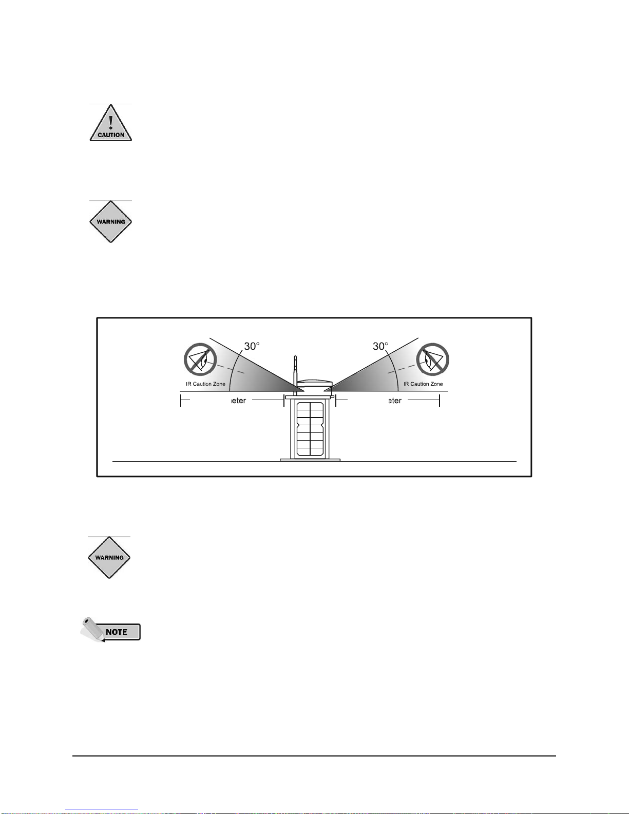
Do not view a Model A704-5 actively emitting infrared or visible light from the side of
the light (close to or on beam) from a range of less than 4 feet (1.2 meters). Please see
the following diagram for further details.
Owner’s Manual | Model A704-5 Aviation Lighting System
A safe limit for near-infrared viewing, established by the American Conference of Governmental and
Industrial Hygienists (ACGIH), is 65mW/in
2
(10mW/cm2) as the maximum exposure limit for viewing for up
to 16 minutes. This power density can be produced by a Model A704-5 at the lens surface when actively
emitting infrared light. High-power visible-spectrum LEDs also pose an eye safety risk if viewed
inappropriately.
4 feet
(1.2 m)
4 feet
(1.2 m)
Figure 2-1: LED Viewing Precautions
2.2 Battery Precautions
Use extreme caution when handling the light. This product is capable of generating
enormous short-circuit currents. Remove all jewelry (bracelets, metal-strap watches,
rings) before attempting to handle or remove the batteries.
Take care when connecting or disconnecting cables. A damaged cable can cause
problems with the electrical circuit. For instructions on disconnecting and recon necting
the batteries within the light, see Appendix A: Battery Replacement.
5
© 2008 Carmanah Technologies Corporation
Last revised: April 2008
Owner’s Manual | Model A704-5 Aviation Lighting System
2.3 Electrostatic Discharge (ESD) Precautions
If performing maintenance procedures:
Before performing any light maintenance, dissipate static electricity by touching one of the four head
plate screws.
When possible, use a properly grounded antistatic wrist strap.
Prevent damage to the connectors by aligning connector pins carefully before you connect the cable.
Misaligned connector pins can cause damage to system components at power-on.
2.4 Storage Precautions
When in storage, the A704-5 light will require periodic recharging to maximize the life expectancy of its
batteries. The interval between recharging is dependent upon the temperature where the light is stored.
Table 2-1: Recharge Intervals provides the recommended maximum storage interval between charging
as it relates to storage temperature.
The rate of battery self-discharge is very dependent upon temperature. The warmer the
temperature, the faster the batteries will discharge. Specifically, for every rise in
temperature of 16 degrees Fahrenheit, the battery storage life is reduced by one-half.
Storage in a cool area (under 68 degrees Fahrenheit) is recommended.
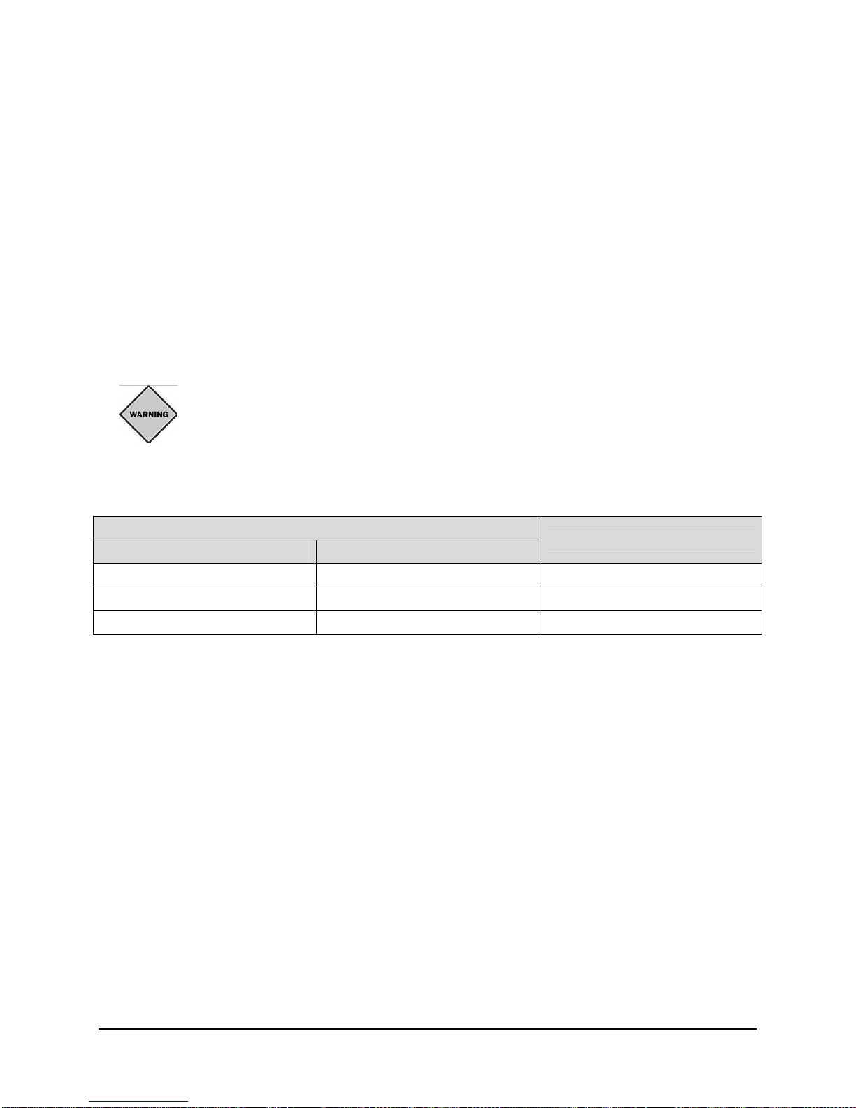
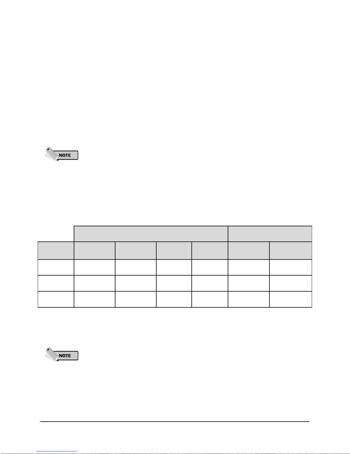
Table 2-1: Recharge Intervals
Storage Temperature
˚C ˚F
20 or lower 68 or lower 3
20 to 40 68 to 104 1
40 or higher 104 or higher Twice Monthly
Recharge Interval [Months]
See section 9.0 Maintenance and Product Care for information on recharging the A704-5 light.
2.5 Wireless Precautions
Keep the controller at a distance of at least three feet (one meter) from the antennas of lights or other
controllers. The controller sends out a powerful radio signal that could damage sensitive receiver
circuitry if operated at close range.
Ensure the antenna is attached to the wireless controller and light before operating. Failure to do so
can result in damage to the product and voiding warranty.
Firmly tighten the light and controller antennas by hand. Do not use tools.
2.6 Other Precautions
Do not lift the light by the top solar panel; use the handle.
Do not clean any part of the light with abrasive cleaners; use a soft cloth with mild soap and water.
Do not install antennas or other connectors when there is dirt, moisture, or debris on the connectors.
The contacts can be cleaned with a jet of compressed air or an ozone-friendly gas.
6
© 2008 Carmanah Technologies Corporation
Last revised: April 2008
3.0 Component Identification
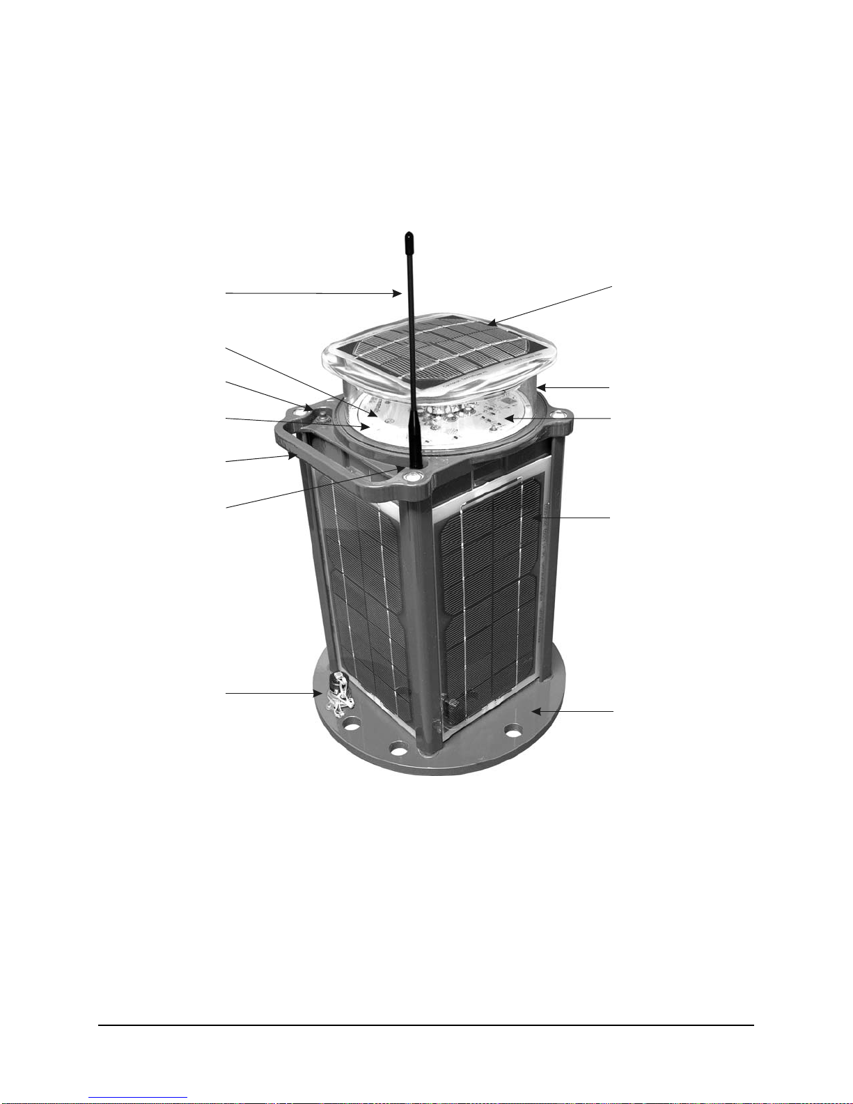
3.1 Model A704-5 Light
Owner’s Manual | Model A704-5 Aviation Lighting System
Optional antenna
Reflector
Push button
Indicator LEDs
Handle
Antenna connector
External power
connector
Top solar panel
Lens
Main beam LEDs
Side solar panels
Base plate with
mounting holes
Figure 3-1: Model A704-5 Light Component Identification
7
© 2008 Carmanah Technologies Corporation
Last revised: April 2008
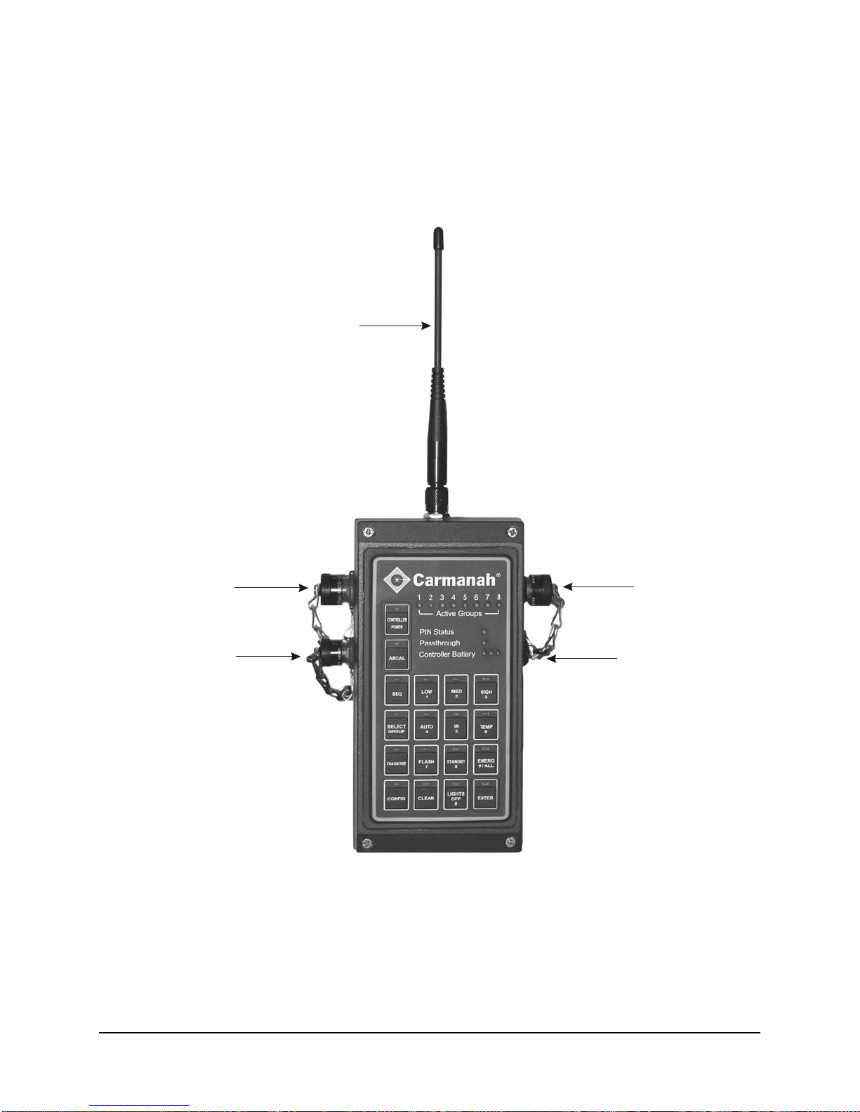
3.2 Wireless Controller
Antenna
Owner’s Manual | Model A704-5 Aviation Lighting System
Communications
connector
External power
connector
Figure 3-2: Wireless Controller Component Identification
ARCAL
connector
Vent
8
© 2008 Carmanah Technologies Corporation
Last revised: April 2008

Owner’s Manual | Model A704-5 Aviation Lighting System
4.0 Model A704-5 Aviation Light Operation
4.1 Understanding the Product
The model A704-5 aviation light is available in wireless and non-wireless models. This manual refers
primarily to the wireless version.
1
The Model A704-5 Aviation Light does not require an external power supply. It operates using solarcharged replaceable batteries that are typically maintenance-free for up to five years. The main body of
the Model A704-5 consists of a rugged aluminum housing that contains the batteries, an external power
connector (for attaching an external DC charger), and four solar panels mounted on the sides. The top
head/lens assembly consists of:
a push button for control of light functions
electronics
light emitting diodes (LEDs) and optics all enclosed within a clear polycarbonate lens
a top solar panel, and
an antenna (optional)
Installing the light requires no special training and can be done e asily and quickly.
Unlike conventional airfield lights, the Model A704-5 Aviation Light offers six distinct output modes:
Three 'Autonomous' output modes for continual sustained dusk-to-dawn operation
Three ‘Temporary’ high-intensity output modes for short-term operation
Each output mode can be selected by pressing a push button on the light itself or by using the optional
wireless controller. If the light needs to be extinguished immediately, a single press of the push button
places the light into Standby Mode. When in Standby Mode the Model A704-5 will not illuminate until the
next nightfall.
During the day, the Model A704-5 charges from sunlight. The capacity of the Model A704-5’s battery
ensures that even with poor levels of sunlight over extended periods, the light has enough reserve power
to continue to perform reliably. The Model A704-5 is completely power-autonomous; wiring to an external
power supply is not required in most cases. This independence allows the Model A704-5 to be deployed
in locations where external power is hard to access or unavailable. If continuous high-intensity output is
desired, external power can be supplied via the power connector in the light’s base. On mo dels equipped
with the IR option, infrared LED operation can also be selected.
If the Model A704-5 does not detect daylight for twenty-four hours, it will automatically turn itself off and
go into Ship Mode. For more information, see Ship Mode in section 4.3.2 Push Button Operation.
4.2 Model A704-5 Light Quick Start Guide
This guide provides instructions to follow upon initial receipt of the Model A704-5 lights. Detailed
operational and programming instructions are described later in this owner’s manual.
1. Upon receivin g the Model A704-5 light, follow these steps:
2. Unpack the light from the box it was shipped in and remove the warranty card. Keep the shipping box
intact and organized – do not discard the box or cardboard inserts.
3. If the A704-5 lights are equipped with the optional wireless control system, remove the dust cap on
the antenna connector, and thread on the removable antenna. Firmly tighten the antenna by hand.
Store the dust cap for later use by fitting it snugly on the tip of the antenna.
1
Note: The wireless A704-5 does not transmit, but rather receives transmissions.
9
© 2008 Carmanah Technologies Corporation
Last revised: April 2008

Owner’s Manual | Model A704-5 Aviation Lighting System
4. Place all the lights physically close together – preferably in a dark place that is dark enough to
observe the LED operation and so that the light thinks that it is night.
5. The lights will all be in Ship Mode. To get the lights out of Ship Mode, quickly press the small black
push button switch on the top of the light (to the left of the handle) twice. Quick presses are required –
do not hold the button down for more than half a second. (If the lights are in a dark location, they will
turn on in the Autonomous Low setting shortly after the button presses.)
The lights are now ready to accept further programming commands using either the pu sh button, or the
wireless controller (for lights with the wireless control system). The lights can now be deployed, and will
operate in the equipped mode (Autonomous Low) from dusk until dawn.
For further information on programming and advanced operation see section 4.3 Programming Options.
4.3 Programming Options
There are two options for programming the Model A704-5 light:
Push Button: The black push button on the top of the Model A704-5 allows manual programming of the
Model A704-5 features and operation.
Wireless Controller: The wireless controller is capable of performing all push button operations as well
as several advanced operations. See section 5.0 Wireless Controller Operation.
4.3.1 Indicator LEDs
Located near the push button inside the lens are three small indicator LEDs that light up as either g ree n,
amber or red. (See section 3.0: Component Identification).
Indicator LEDs are used to:
Guide push button operation (for more detail, see section 4.3.2 Push Button Operation)
Indicate diagnostic information such as battery state of charge
Indicate operating state after the button has not been used for 10 seconds:
The green indicator LED flashes once every 2 seconds when the light is not in Ship Mode or
optional Infrared Mode.
The amber indicator LED flashes once every 2 seconds when the light is charging, using its solar
panels, or once every second when charging via the external power connector.
When the light is in Ship Mode, no indicator LEDs will light unless the light is charging.
When the light is in Infrared Mode (optional), no indicator LEDs will light or flash.
10
© 2008 Carmanah Technologies Corporation
Last revised: April 2008

Owner’s Manual | Model A704-5 Aviation Lighting System
4.3.2 Push Button Operation
The two types of button presses that will be accepted by the light as programming commands are:
Hold:
Pressing and holding the button down for several seconds cycles through the Model A704-5
command levels (see Table 4-1: Overview of Command Levels and Modes). Each
command level is indicated by the number of flashes from the amber indicator LED; one
blink indicates the first level, two blinks indicates the second level, etc. The amber indicator
LED indicates acceptance of a command for a button hold by flashing one to five times
depending on the command level. Once the desired command level has been reached,
release the push button.
Press:
Pressing the button for a fraction of a second enters the command within that level. The
green indicator LED indicates acceptance of a button press by flashing the same number of
times afterwards. The red indicator LED flashes three times if the command has not been
accepted due to button lockout. You must press the push button within 10 seconds of
releasing the hold, otherwise the light will exit the Programming Mode.
Table 4-1: Overview of Command Levels and Modes illustrates the order of commands and modes for
programming the Model A704-5. This table is followed by a description of the light’s operation in each
mode. Read this table from left to right.
Table 4-1: Overview of Command Levels and Modes
Step 1: Choose Command Level Step 2: Choose Command – Action (Response)
1 press
Command Level
(No Amber
Flash)
(1 Amber
Flash)
(2 Amber
Flashes)
(3 Amber
Flashes)
(4 Amber
Flashes)
(5 Amber
Flashes)
0: Autonomous
1: Temporary Temp Low Temp Med Temp High No action No action
2: Ship Ship Mode
3: Infrared
4: Diagnostics
5: Configuration No action
(1 Green
Indicator LED
Flash)
Standby
2
Mode
Infrared
Toggle
Battery
Check
2 presses
(2 Green
Indicator LED
Flashes)
Autonomous
Low
Do Not Use
No action No action No action No action
UCS Status No action No action No action
Button Lock
Toggle
3 presses
(3 Green
Indicator LED
Flashes)
Autonomous
Med
3
Do Not Use4
Temp
Timeout
Toggle
4 presses
(4 Green
Indicator LED
Flashes)
Autonomous
High
No action No action
No action
5 presses
(5 Green
Indicator LED
Flashes)
Flash Toggle
Factory
Reset
2
If the light is switched directly from Standby Mode to Autonomous mode, the light will remain off until the next time it detects a day-
to-night transition. When this is done in low lighting conditions such as an office or warehouse, the light will NOT turn on because
it considers it to be nighttime and is awaiting the next day-to-night transition before illuminating. If you would like to force the light to
turn on in Autonomous mode to verify the light illuminates, place it in a Temporary mode first and then into an Autonomous
mode. The light will now illuminate immediately in low lighting conditions.
3
For engineering test purposes only. Use may result in unpredictable behavior of the light.
4
For engineering test purposes only. Use may result in unpredictable behavior of the light.
11
© 2008 Carmanah Technologies Corporation
Last revised: April 2008

Owner’s Manual | Model A704-5 Aviation Lighting System
Some finer points of button usage include:
To more quickly cycle through the command levels, try releasing the button briefly
when each amber flash occurs, and then pressing it down again (e.g. for command
level 3: hold the button until the amber LED flashes once, then release it briefly and
hold it down again until the amber LED flashes twice, release briefly and hold down
until it flashes three times).
Example: To set the Model A704-5 to Ship Mode, follow these steps:
1. Hold the push button down. The amber indicator LED will blink once after approximately two seconds
and twice after approximately four seconds.
Release the push button.
Immediately press the button once. The green LED will blink once to confirm one press. The red LED will
then briefly flash as the light enters Ship Mode.
The Model A704-5 is now in Ship Mode.
In the following sections, shorthand terminology is used to refer to particular push hold
/ button press sequences in the format: [x, y] specifying hold for x amber flashes, press
y times followed by y green flashes. For example, [0, 5] is Flash Toggle; [4, 1] is
Battery Check. [0] = no hold; proceed directly to the press.
Button Sequence [0, 1]: Standby Mode
Button sequence [0, 1] puts the Model A704-5 in Standby Mode. This will immediately extinguish the light,
and the light will resume autonomous operation at its last set Autonomous Output Mode after detecting a
day-to-night transition.
If a light is in a Temp Mode and is put into Standby Mode, it reverts to the last programmed Autonomous
setting (and will turn on in the next day-night transition).
Button Sequence [0, 2-4]: Autonomous Output Modes
The Model A704-5 has three Autonomous Output Modes: low, medium, and high intensity. These are the
standard operating modes for dusk to dawn operation when the light is deployed differing by light
intensity. The Autonomous Modes operate independently of an external power source as long as local
sunlight conditions can adequately sustain the battery state of charge.
If the light is put into an Autonomous Mode during the day or in a bright environment,
the main LEDs will remain off until the light senses nightfall. If the Model A704-5 is
programmed to the Autonomous Mode at night or in low-light conditions, the main
LEDs will be on until daylight is detected.
Button [0, 5]: Flash Toggle
The flash toggle setting alternates the light between steady-on or flashing. In Flash Mode, the light
flashes at once per second (0.3 seconds on, 0.7 seconds off). The three Autonomou s Outpu t Modes (low,
medium and high) can be either steady-on or flashing.
When in Autonomous Mode, the Model A704-5 may automatically decrease its intensity if it detects that it
does not have sufficient battery charge to continue autonomous operation at that brightness. When the
Model A704-5 detects that it is receiving sufficient battery charge to resume autonomous operation at the
original user setting, it revert to its original intensity. For more information, see section 4.3.3 Automatic
Light Control (ALC).
12
© 2008 Carmanah Technologies Corporation
Last revised: April 2008
Owner’s Manual | Model A704-5 Aviation Lighting System
Button Sequence [1, 1-3]: Temporary High-Intensity Modes
The Model A704-5 has three temporary, high-intensity output modes: low, medium, and high. These
modes are typically used when the Model A704-5’s maximum or near maximum output is required for a
brief period of time – such as poor visibility due to bad weather conditions. To activate a high-intensity
output mode, use [1, 1] for low, [1, 2] for medium, and [1, 3] for high. Day or night, the Model A704-5 will
immediately turn on at the selected temporary high-intensity setting, and will remain on for one hour. At
the end of this hour, the Model A704-5 will resume operation in its last set Autonomous Mode. The highintensity output can be cancelled by selecting an Autonomous Output Mode or by setting the Model A7045 into either Standby Mode [0, 1] or Ship Mode [2, 1].
Prolonged and repeated use of high-intensity settings of the Model A704-5 will cause
rapid battery depletion and use more energy than the solar panels can collect in a day.
It is important to budget energy use to match solar conditions.
If the Temporary Timeout [5, 3] toggle is off and there is external power applied to the
Model A704-5, then the light will remain in a programmed temporary high-intensity
setting until commanded otherwise (or until the light detects that external power is no
longer available). For more on this, see Button Sequence [5, 3] Temporary HighIntensity Mode Timeout.
If the wireless handheld controller is used to invoke a temporary High-Intensity Mode,
the lights will remain on for only 15 minutes before resuming their last Autonomous
Mode. See section 5.6.4 Temporary Operation Mode.
Output peak intensities for each setting are as follows:
Table 4-2: Output Intensities (based on Warm White LEDs)
Visible LEDs Infrared (870nm) LEDs
(optional)
Intensity Autonomous
Steady-on
Low 6 cd 10 cd 52 cd 34 cd 15 mW/sr 9 mW/sr
Med 10 cd 20 cd 63 cd 43 cd 30 mW/sr 18 mW/sr
High 16 cd 32 cd 95 cd 57cd 60 mW/sr 36 mW/sr
Autonomous
Flashing
TempSteady-on
TempFlashing
Steady-on Flashing
The flashing intensities in Table 4-2: Output Intensities (based on Warm White LEDs)
are effective intensities derived using the Schmidt-Clausen method
Autonomous steady-on and flashing modes at a given intensity setting (Low, Medium
or High) provide the same autonomy. Temporary flashing modes offer greater
autonomy than Temporary steady-on modes, for a given intensity setting (Low,
Medium or High). This is why the Autonomous flashing intensities in Table 4-2: Output
Intensities (based on Warm White LEDs) are higher than the Autonomous steady-on
ones, and the Temp flashing intensities are lower than the Temp steady-on ones.
13
© 2008 Carmanah Technologies Corporation
Last revised: April 2008
Owner’s Manual | Model A704-5 Aviation Lighting System
Button Sequence [2, 1]: Set Ship Mode
Ship Mode is used for shipping or long-term storage to preserve battery life. To set the Model A704-5 into
Ship Mode, hold the button until the amber LED flashes twice, then release. Immediately press the button
once to put the Model A704-5 into Ship Mode. When in Ship Mode, the Model A704-5 will remain off until
the push button is pressed. A day-to-night transition will not activate the Model A704-5 when in this mode.
Only an Autonomous or Temporary command-level push button input will activate it (see Table 4-1:
Overview of Command Levels and Modes).
A704-5 lights equipped with the wireless control system will not respond to wireless
commands when in Ship Mode.
Button Sequence [3, 1]: Infrared Toggle
Observe precautions when the Model A704-5 is in IR Mode. Refer to section 2.1
Viewing Precautions for details.
If the infrared LED option is installed on your Model A704-5, it can be toggled between Visible Light Mode
and IR Mode. To toggle into IR Mode, use button sequence [3, 1]. Repeat this sequence to toggle the
Model A704-5 back into visible light operation.
If your Model A704-5 lights aren’t equipped with the optional infrared LEDs, the infrared toggle will have
no effect. The Model A704-5 will continue to operate in the visible light mode last set.
When infrared mode is toggled on, the Model A704-5 will continue operating in whatever mode it was
previously programmed for (i.e. intensity and flash/steady on), except that it will be emitting infrared
instead of visible light. The indicator LEDs will not display anything when the light is in IR Mode, to
prevent the Model A704-5 from emitting any visible light.
Button Sequence [4, 1]: Battery Status Check
To determine the battery status of the Model A704-5, use button sequence [4, 1] to request a battery
status check. The indicator LEDs will show the battery status for 10 seconds as follows:
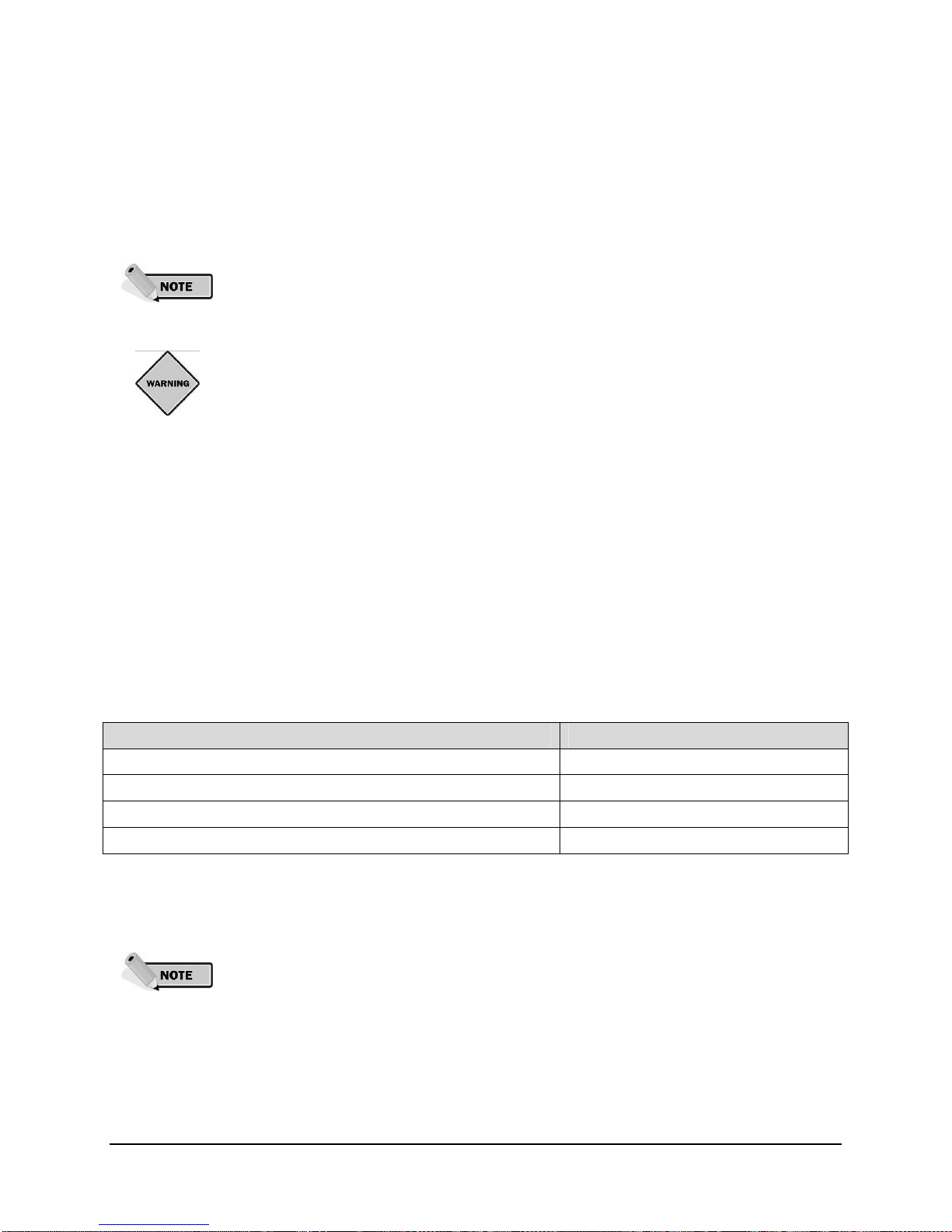
Table 4-3: Battery Indicator LEDs
Indicator LED Response While in Battery Status Check Mode Corresponding Battery Charge
Green 75% – 100%
Amber 50% – 75%
Red 5% – 50%
Flashing Red Less than 5%
Low battery state: If the detected battery charge at any time falls below 5%, the light
will enter the low battery state. In this mode the light will emit a short flash once every
minute (either in visible or IR light depending on its setting). The light will not exit low
battery state until the detected battery level exceeds 40% for 10 minutes. On exit from
low battery state, the light will enter its previously set autonomous state.
Lights may report artificially high battery levels during and immediately following
charging (both solar and via the optional AC/DC charger).
14
© 2008 Carmanah Technologies Corporation
Last revised: April 2008
Owner’s Manual | Model A704-5 Aviation Lighting System
Button Sequence [4, 2]: UCS Status
To determine if the UCS is enabled or disabled on the A704-5, use button sequence [4, 2] to request the
UCS status. The indicator LEDs will blink 3 times to show the UCS status as follows:
Table 4-4: Indicator LEDs
Indicator LED Response While in UCS Status Check Mode UCS Status
Amber Enabled
Red Disabled (default)
Button Sequence [5, 2]: Push Button Lock Toggle
The Model A704-5 switch can be locked so that inadvertent button presses will not accidentally modify
the light’s operation. This is a useful feature for transporting the light, or for when it is important that it not
be accidentally reprogrammed in the field. To lock or unlock the light, use button sequence [5, 2]. Red
flashes indicate when the light enters locked mode, and two green flashes when the light exits locked
mode. When locked, the red indicator LED will flash three times each time any other command is given,
other than the unlock command, to indicate that the light is in this mode.
Button Sequence [5, 3]: Temporary High-Intensity Mode Timeout
This function toggles on/off the Temporary High-Intensity Timeout (Temp Timeout). With the Temp
Timeout toggle is on, the light always stays on for one hour when placed into a temporary high-intensity
setting using the pushbutton switch. When the Temp Timeout toggle is off, and the light senses that it’s
connected to an active 12V DC source, the light will stay on indefinitely when placed into a temporary
setting. Regardless of the Temp Timeout toggle setting, if the light senses that it’s not connected to a 12V
DC source, it will stay on for one hour to avoid overly depleting the batteries.
Table 4-5: Indicator LEDs
Light behavior when put in a Temporary High-Intensity Mode using the
pushbutton switch
Temp Timeout Toggle Status 12V DC detected 12V DC not detected
On (default) Turns off after 1 hour Turns off after 1 hour
Off Stays on until 12V DC not detected Turns off after 1 hour
Button Sequence [5, 5]: Factory Reset
This will reset the A704-5 light back to the factory defaults, meaning that you will not be
able to use the light with the wireless controller if it has been configured with a UCS.
The A704-5 light uses the following factory defaults:
Autonomous Low
Flashing Off
Infrared Off
Temporary Timeout On
A704-5 lights equipped with the wireless control system are configured with these
additional settings:
Assigned to Group 1
UCS Disabled
15
© 2008 Carmanah Technologies Corporation
Last revised: April 2008
Owner’s Manual | Model A704-5 Aviation Lighting System
4.3.3 Automatic Light Control (ALC)
Automatic Light Control (ALC) is a patented algorithm that allows the light to adjust its energy
consumption to the amount of sunlight available to charge the batteries. This ensures the light will
continue to operate through periods of limited sunlight.
ALC is always enabled in the Model A704-5 for Autonomous Modes and it is not user configurable. ALC
is disabled for Temporary High-Intensity Modes.
These thresholds are not to be confused with battery state-of-charge thresholds.
Table 4-6: ALC Dimming Levels
State of Charge ALC Dimming Level
60% - 100% 100% intensity
50% - 60% 75% intensity
40% - 50% 50% intensity
0% - 40% 25% intensity
4.3.4 24-Hour Shutoff
If the Model A704-5 senses ambient light levels of 30 lux or less for 24 consecutive hours, it will assume it
is being stored and automatically enter Ship Mode to preserve the battery. The ambient light thresholds
are set so that a very dark winter season will not cause the Model A704-5 to enter Ship Mode
unintentionally.
The A704-5 will still charge while in Ship Mode as long as sunlight is available or if
external power is connected.
16
© 2008 Carmanah Technologies Corporation
Last revised: April 2008
 Loading...