

Carl Wittkopp GatorSignal Plus Installation Instruction

Installation instruction GatorSignal Plus
Content
1 Notes __________________________________________________________________________ 2
1.1 Liability notes _________________________________________________________________ 2
2 Introduction ____________________________________________________________________ 2
3 Signals _________________________________________________________________________ 2
3.1 In-/outputs ___________________________________________________________________ 2
3.1.1 Inputs ______________________________________________________________________ 2
3.1.2 Ouptuts ____________________________________________________________________ 3
4 Plug position ____________________________________________________________________ 3
4.1 Gator 2000 ___________________________________________________________________ 3
4.2 Gator 3000/3010 _____________________________________________________________ 3
4.3 Gator 5000 ___________________________________________________________________ 3
4.4 Gator 6000/8000/9000 _______________________________________________________ 3
5 System _________________________________________________________________________ 4
5.1 System diagram _______________________________________________________________ 4
5.2 Power supply __________________________________________________________________ 4
6 Technical data __________________________________________________________________ 5
7 Mounting ______________________________________________________________________ 6
7.1 Case _________________________________________________________________________ 6
7.2 Break-out for wiring ____________________________________________________________ 6
7.3 Terminal assignment ___________________________________________________________ 7
7.3.1 Terminal assignment description _______________________________________________ 7
7.3.2 Clamping strip ______________________________________________________________ 7
7.4 Internal assignment input _______________________________________________________ 8
7.4.1 Internal assignment output ____________________________________________________ 8
7.5 Activate/deactivate I/Os ________________________________________________________ 8
© Carl Wittkopp GmbH - Errors and omissions excepted
Rel. 1.1 14.06.2016 Installation instructions no. 9999-149-0

Installation instruction GatorSignal Plus
1 Notes
• Please read these instructions carefully before operating the lock.
1.1 Liability notes
• The installation of this signal box has to be done according to these instructions
• The installation instruction is part of VdS certification and the certification of other testing institutes.
• Non-compliance leads to the loss of this certification.
• When operating beyond the specifications the warranty of the manufacturer will be void.
• Take care of not damaging the cables and all connected components.
2 Introduction
• The connection box “GatorSignal Plus“ is a universal interface for exchanging signals of locks within the Gator series with
external systems via potential-free contacts. This includes the function as blocking device and the signalization of a silent
alarm.
• It offer the possibility of power supplying a lock system (containing of several locks and/or input units).
• Up to two locks or locking electronics can be connected to one box. Inside of redundant locks there are two independent
electronics. They work as two separate locks.
3 Signals
• The following signals can be processed or generated independently from the configuration
• Concerning the adjustment of signals of pre-defined levels 10, 20, 30 we refer to the ”General operating notes levels 10,
20, 30”.
3.1 In-/outputs
• Every lock electronic has got 3 outputs and 2 inputs. The assignment is generally freely configurable and is done via PC
software Gator Select. For the standard configurations (level 10, 20, 30) they are already configured.
• The signals on the input take effect on both connected locks/lock electronics. In that manner a boltwork switch can be processed by two electronics at the same time.
• With two connected lock electronics one output each is connected if at least one has the condition “disjunction“.
3.1.1 Inputs
Release contact [blocking device]
Start delay time
Boltwork switch
Blocking signal
System will be blocked when the according controlling
input has got control voltage.
When changing the signal level from the defined idle
state, the delay time 1 is started.
Automatic closing is interrupted until the boltwork is in
closed position. This ensures that the bolt of motor locks
can go into closed position without taking damage.
With an active signal the lock cannot be closed via the
input unit.
The automatic closing is not affected by it.
2
Installation instruction GatorSignal Plus
3.1.2 Ouptuts
Bolt position
Opening delay active
Release window active
Opening window active
For signalling the lock’s bolt position. The contact is active
when the bolt reaches or leaves the closed position.
Note:
If the bolt position should change while the lock is in
standby mode, i.e. with latch bolt locks, the switching
status changes only when the lock is active again.
Silent alarm – By entering the alarm code (last code
number freely adjustable) an alarm signal is triggered and
sent to the burglar alarm system. The lock opens with the
alarm code.
When the opening delay is started the according output
is triggered. The signal can be used for signal lights for
example.
If an opening delay is activated, the according output is
switched. The signal can then be used for i.e. signal lights.
The lock can be opened after the opening delay has ended. This is signaled by the according output.
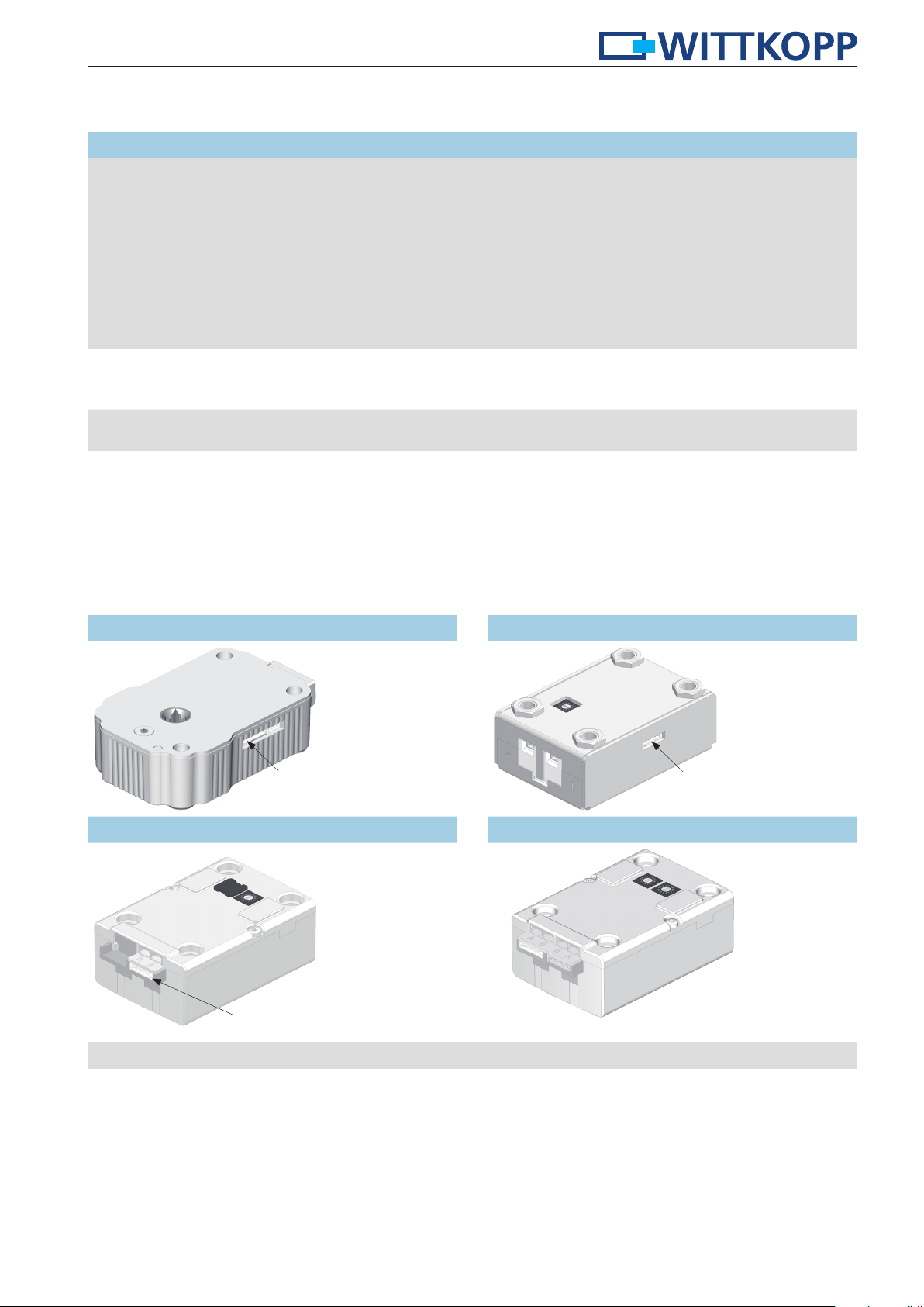
4 Plug position
All locks within the Gator series are equipped with an 8-pin plug to connect to the “GatorSignal Plus“ box.
4.1 Gator 2000 4.2 Gator 3000/3010
GatorSignal Plus (8-pin)
4.3 Gator 5000 4.4 Gator 6000/8000/9000
GatorSignal Plus (8-pin)
GatorSignal Plus (8-pin)
Connect the cable to the according plug for the “Gator Signal Plus“ box.
GatorSignal Plus (8-pin)
3
 Loading...