


PICA II
Operating Manual

Copyright by Carl Valentin GmbH / 7929055.1015
Information on the scope of delivery, appearance, performance,
dimensions and weight reflect our knowledge at the time of printing.
We reserve the rights to make modifications.
All rights, including those regarding the translation, are reserved.
No part of this document may be reproduced in any form (print,
photocopy or any other method) or edited, copied or distributed
electronically without written permission from Carl Valentin GmbH.
Due to the constant further development of our devices discrepancies
between manual and device can occur.
Please check www.carl-valentin.de for the latest update.
Trademarks
All named brands or trademarks are registered brands or registered
trademarks of their respective owners and may not be separately
labelled. It must not be concluded from the missing labelling that it is
not a registered brand or a registered trademark.
Carl Valentin label printers comply with the following safety guidelines:
CE
EG Low-Voltage Directive (2006/95/EC)
EG Electromagnetic Compatibility Directive (2004/108/EC)
Carl Valentin GmbH
Postfach 3744
78026 Villingen-Schwenningen
Neckarstraße 78 – 86 u. 94
78056 Villingen-Schwenningen
Phone
Fax
+49 (0)7720 9712-0
+49 (0)7720 9712-9901
E-Mail
Internet
info@carl-valentin.de
www.carl-valentin.de

Pica II Serie Table of Contents
10.15 Operating Manual 3
Table of Contents
Table of Contents ............................................................................. 3
1 Introduction ............................................................................ 5
1.1 General Instructions ................................................................ 5
1.2 Intended Use ........................................................................... 5
1.3 Environmentally-Friendly Disposal .......................................... 6
1.4 Connector Pin Assignment (Printer Rear) ............................... 6
2 Safety Instructions ................................................................ 7
2.1 Warning Instructions ................................................................ 7
2.2 Operating Conditions ............................................................... 8
3 Technical Data ..................................................................... 13
3.1 Control Inputs and Outputs ................................................... 16
3.2 Plug & Play ............................................................................ 21
4 Installation ............................................................................ 23
4.1 Setting up the Label Printer ................................................... 23
4.2 Connecting the Label Printer ................................................. 24
4.3 Switching on the Label Printer ............................................... 24
4.4 Start-Up ................................................................................. 25
5 Loading Media ..................................................................... 27
5.1 Loading Label Roll ................................................................. 27
5.2 Loading Fan-Fold Labels ....................................................... 32
5.3 Loading Transfer Ribbon ....................................................... 33
6 Control Panel ....................................................................... 35
6.1 Structure of the Control Panel ............................................... 35
6.2 Printer States ......................................................................... 35
6.3 Key Functions ........................................................................ 36
7 Printing ................................................................................. 39
7.1 Processing Print Orders ........................................................ 39
7.2 Status Print ............................................................................ 39
7.3 Label Feed ............................................................................. 40
7.4 Saving Labels ........................................................................ 40
7.5 Tear-off Mode ........................................................................ 40
7.6 Synchronization of Label Feed .............................................. 40
7.7 Dispenser Mode .................................................................... 41
7.8 Cutter Mode ........................................................................... 42
8 Service Functions ................................................................ 43
9 Maintenance and Cleaning ................................................. 47
9.1 General Cleaning ................................................................... 48
9.2 Cleaning the Print Roller ....................................................... 48
9.3 Cleaning the Printhead .......................................................... 49
9.4 Cleaning the Label Photocell ................................................. 50
9.5 Replacing the Printhead (General) ........................................ 51
9.6 Replacing the Printhead ........................................................ 52
9.7 Adjusting the Printhead ......................................................... 53
10 Error Correction ................................................................... 53
11 Index ..................................................................................... 61

Pica II Series Introduction
10.15 Operating Manual 5
1 Introduction
1.1 General Instructions
Important information and instructions in this document are
designated as follows:
DANGER identifies an extraordinarily great and immediate
danger which could lead to serious injury or even death.
WARNING identifies a possible danger would could lead to
serious bodily injury or even death if sufficient precautions
are not taken.
CAUTION indicates a potentially dangerous situation which
could lead to moderate or light bodily injury or damage to
property.
NOTICE gives you tips. They make a working sequence
easier or draw attention to important working processes.
Gives you tips on protecting the environment.
Handling instruction
Optional accessories, special fittings
Time
Information in the display
1.2 Intended Use
The label printer is a state-of-the-art device which complies with the
recognized safety-related rules and regulations. Despite this, a danger
to life and limb of the user or third parties could arise and the label
printer or other property could be damaged while operating the device.
The label printer may only be used while in proper working order and
for the intended purpose. Users must be safe, aware of potential
dangers and must comply with the operating instructions. Faults, in
particular those which affect safety, must be remedied immediately.
The label printer is solely intended to print suitable media which have
been approved by the manufacturer. Any other or additional use is not
intended. The manufacturer/supplier is not liable for damage resulting
from misuse. Any misuse is at your own risk.
Intended used includes heeding the operating manual, including the
maintenance recommendations/regulations specified by the
manufacturer.
NOTICE!
The complete documentation is included in the scope of
delivery on CD ROM and can also currently be found in the
internet.
Introduction Pica II Series
6 Operating Manual 10.15
1.3 Environmentally-Friendly Disposal
Manufacturers of B2B equipment are obliged to take back and
dispose of old equipment that was manufactured after 13 August
2005. As a principle, this old equipment may not be delivered to
communal collecting points. It may only be organised, used and
disposed of by the manufacturer. Valentin products accordingly
labelled can therefore be returned to Carl Valentin GmbH.
This way, you can be sure your old equipment will be disposed of
correctly.
Carl Valentin GmbH thereby fulfils all obligations regarding timely
disposal of old equipment and facilitates the smooth reselling of these
products. Please understand that we can only take back equipment
that is sent free of carriage charges.
Further information on the WEEE directive is available on our website
www.carl-valentin.de.
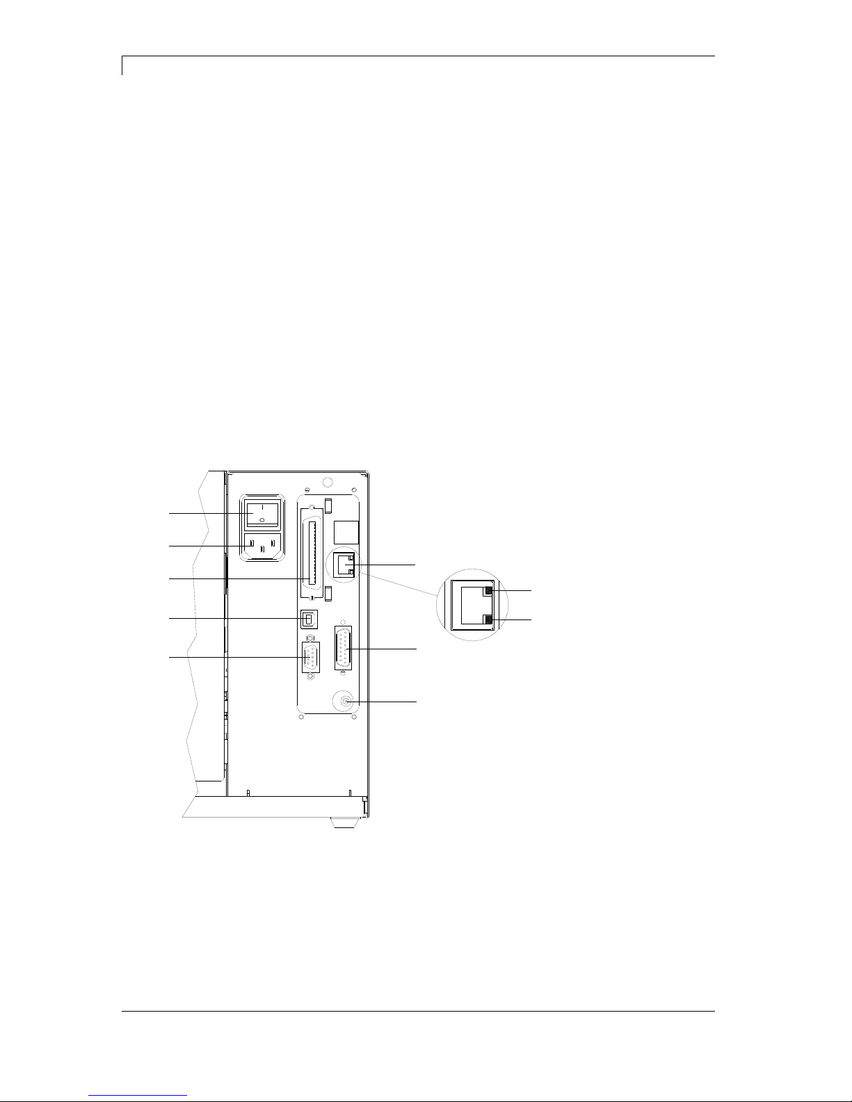
1.4 Connector Pin Assignment (Printer Rear)
H
B
C
D
A
1
2
F
G
E
Figure 1
A Ethernet 10/100 Interface
B External Output/Input (Option)
C Winder Connection
D Serial Interface RS-232
E USB Interface
F Centronics
G Power Supply
H Switch On/Off
1 - LED orange
1 - Lighting = Connection active
1 - Flashing = Data transfer
1 - Off = No connection
2 - LED green
2 - Lighting: Speed 100 MBit
2 - Off: Speed 10 MBit
Pica II Series Safety Instructions
10.15 Operating Manual 7
2 Safety Instructions
The label printer is configured for a voltage of 230 V. It has to be
plugged into a grounded socket only.
Couple the label printer to devices using extra low voltage only.
Before making or undoing connections, switch off all devices involved
(computer, printer, accessories etc.).
Operate the label printer in a dry environment only and do not get it
wet (sprayed water, mist etc.).
In case of cleaning and maintenance with an open printer cover,
ensure that clothing, hair, jewellery and similar personal items do not
contact the exposed rotating parts.
The print unit can get hot during printing. Do not touch the printhead
during operation. Cool down the print unit before changing material,
removal or adjustment.
Carry out only the actions described in these operating instructions.
Any work beyond this may only be performed by the manufacturer or
upon agreement with the manufacturer.
Unauthorized interference with electronic modules or their software
can cause malfunctions.
Other unauthorized work or modifications to the direct print module
can endanger operational safety.
Always have service work done in a qualified workshop, where the
personnel have the technical knowledge and tools required to do the
necessary work.
There are warning stickers on the direct print modules that draw your
attention to dangers. Therefore the warning stickers are not to be
removed as then you and others cannot be aware of dangers and may
be injured.
DANGER!
Danger to life and limb from power supply!
Do not open the printer casing.
2.1 Warning Instructions
Warnings are presented with three signal words for the different levels
of danger.
DANGER identifies an extraordinarily great and immediate danger
which could lead to serious injury or even death.
WARNING identifies a possible danger would could lead to serious
bodily injury or even death if sufficient precautions are not taken.
CAUTION indicates a potentially dangerous situation which could lead
to moderate or light bodily injury or damage to property.
Safety Instructions Pica II Series
8 Operating Manual 10.15
2.2 Operating Conditions
Before initial operation and during operation these operating conditions
have to be observed to guarantee save and interference-free service
of our printers.
Therefore please carefully read these operating conditions.
Shipment and storage of our printers are
only allowed in original
packing.
Installation and initial operation of printer is only allowed if operating
conditions were
fulfilled.
Initial operation, programming, operation, cleaning and service of our
printers are only recommended after careful study of our manuals.
Operation of printer is only allowed by especially trained persons.
NOTICE!
Perform trainings regularly.
Content of the training are chapter 2.2 (Operating Conditions),
chapter 5 (Loading Media) and chapter 9 (Maintenance and
Cleaning).
These indications are also valid for someone else's equipment
supplied by us.
Only use original spare and exchange parts.
Please contact the manufacturer with respect to spare/wear parts.
CPU of printer is equipped with a lithium battery (type CR 2032) for
which the battery regulation is to apply. This regulation plans that
unloaded batteries have to be given to used battery collecting
containers of trade and public carries. In case that batteries were not
completely discharged you have to make arrangements for shortcircuits. At a shutdown of printer the battery has to be disposed in
either case separately from printer.
DANGER!
Danger of life by explosion!
Use non-conducting tools.
The installation place of printer should be even, free of vibration and
currents of air are to be avoided.
The printers have to be installed to ensure optimal operation and
servicing.
Instructions for
lithium battery
Conditions for
installation place

Pica II Series Safety Instructions
10.15 Operating Manual 9
The installation of the power supply to connect our printers has to be
effected according to the international rules and regulations,
especially the recommendations of one of the three following
commissions:
International Electronic Commission (IEC)
European Committee for Electro technical Standardisation
(CENELEC)
Verband Deutscher Elektrotechniker (VDE)
Our printers are constructed according to VDE and have to be
connected to a grounded conductor. The power supply has to be
equipped with a grounded conductor to eliminate internal interfering
voltage.
Power line voltage and power line frequency: See type plate
Allowable tolerance of power line voltage:
+6% … −10% of nominal value
Allowable tolerance of power line frequency:
+2% … −2% of nominal value
Allowable distortion factor of power line voltage: <=5%
In case your net is infected (e.g. by using thyristor controlled
machines) anti-interference measures have to be taken. You can use
one of the following possibilities:
Provide separate power supply to our printers.
In case of problems please connect capacity-decoupled isolation
transformer or similar interference suppressor in front of our
printers.
Emitted interference according to EN 61000-6-4: 01-2007 industrial
sector
Interference voltage to wires according to EN 55022: 05-2008
Interference field power according to EN 55022: 05-2008
System perturbation according to EN 61000-3-2: 04-2006
Flicker according to EN 61000-3-3: 09-2008
Installation of
power supply
Technical data of
power supply
Anti-interference
measures
Stray radiation and
immunity from
disturbance

Safety Instructions Pica II Series
10 Operating Manual 10.15
Immunity to interference according to EN 61000-6-2: 2005
industrial sector
Stray radiation against discharge of static electricity according to
EN 61000-4-2: 12-2001
Electromagnetic fields according to EN 61000-4-3: 11-2003,
ENV 50204: 03-1995
Fast transient burst according to EN 61000-4-4: 07-2005
Surge according to EN 61000-4-5: 12-2001
High-frequency tension according to EN 61000-4-6: 12-2001
Voltage interruption and voltage drop according to
EN 61000-4-11: 08-2004
NOTICE!
This is a machine of type A. This machine can cause
interferences in residential areas; in this case it can be required
from operator to accomplish appropriate measures and be
responsible for it.
All connecting lines have to be guided in shielded lines. Shielding has
to be connected on both sides to the corner shell.
It is not allowed to guide lines parallel to power lines. If a parallel
guiding cannot be avoided a distance of at least 0.5 m has to be
observed.
Temperature of lines between: −15 … +80 °C.
It is only allowed to connect devices which fulfil the request 'Safety
Extra Low Voltage' (SELV). These are generally devices which are
checked corresponding to EN 60950.
The data cables must be completely protected and provide with metal
or metallised connector housings. Shielded cables and connectors are
necessary, in order to avoid radiant emittance and receipt of electrical
disturbances.
Allowable lines
Shielded line:
4 x 2 x 0,14 mm² ( 4 x 2 x AWG 26)
6 x 2 x 0,14 mm² ( 6 x 2 x AWG 26)
12 x 2 x 0,14 mm² (12 x 2 x AWG 26)
Sending and receiving lines have to be twisted in pairs.
Maximum line length:
with interface V 24 (RS-232C) - 3 m (with shielding)
with Centronics - 3 m (with shielding)
USB - 3 m
Ethernet - 100 m
Stray radiation and
immunity from
disturbance
Connecting lines to
external machines
Installation of
data lines

Pica II Series Safety Instructions
10.15 Operating Manual 11
To avoid inadmissible heating, free air convection has to be ensured.
Protection according IP: 20
Ambient temperature °C (operation): Min. +5 Max. +35
Ambient temperature °C (storage): Min. −20 Max. +60
Relative air humidity % (operation): Max. 80
Relative air humidity % (storage): Max. 80
(bedewing of printers not allowed)
We do not take any responsibility for damage caused by:
Ignoring our operating conditions and operating manual.
Incorrect electric installation of environment.
Building alterations of our printers.
Incorrect programming and operation.
Not performed data protection.
Using of not original spare parts and accessories.
Natural wear and tear.
When (re)installing or programming our printers please control the
new settings by test running and test printing. Herewith you avoid
faulty results, reports and evaluation.
Only specially trained staff is allowed to operate the printers.
Control the correct handling of our products and repeat training.
We do not guarantee that all features described in this manual exist in
all models. Caused by our efforts to continue further development and
improvement, technical data might change without notice.
By further developments or regulations of the country illustrations and
examples shown in the manual can be different from the delivered
model.
Please pay attention to the information about admissible print media
and the notes to the printer maintenance, in order to avoid damages
or premature wear.
We endeavoured to write this manual in an understandable form to
give and you as much as possible information. If you have any queries
or if you discover errors, please inform us to give us the possibility to
correct and improve our manual.
Air convection
Limit values
Guarantee

Pica II Series Technical Data
10.15 Operating Manual 13
3 Technical Data
Pica II 104/8 Pica II 106/12 Pica II 103/8 T Pica II 108/12 T
Print Resolution 200 dpi 300 dpi 203 dpi 300 dpi
Max. Print Speed 100 mm/s 100 mm/s 100 mm/s 100 mm/s
Print Width 104 mm 105,7 mm 104 mm 108,4 mm
Passage Width 110 mm 110 mm 110 mm 110 mm
Printhead Flat Type1 Flat Type1 Flat Type2 Flat Type2
Labels
Labels/Continuous Material Rolls, Fan-Fold, Paper, Cardboard, Textile, Synthetics
Max. Material Weight 220 g/m² (larger on demand)
Min. Label Width 15 mm
Min. Label Height
Standard 6 mm
Cutter/Dispenser Mode 15 mm
Max. Label Height
Standard (higher on demand) 750 mm
Option Ethernet 650 mm
Max. Roll Diameter
Internal Unwinder 180 mm
Internal Rewinder --Core Diameter 40 mm / 75 mm (Option)
Winding Outside or Inside
Label Sensor
Standard Transmission
Option Transmission + Reflexion from above / from below
Transfer Ribbon (for thermal transfer printer only)
Ink outside or inside (option)
Max. Roll Diameter Ø 70 mm
Core Diameter 25,4 mm / 1″
Max. Length 300 m
Max. Width 110 mm
Dimensions (mm)
Width x Height x Depth 230 x 230 x 350
Weight 9 kg
Electronics
Processor High Speed 32 Bit
RAM 16 MB
Battery Cache For Real Time Clock (Storage of Data with Shut-Down)
Warning Signal Acoustic Signal when Error
Interfaces
Serial RS-232C (max. 115200 Baud)
Parallel Centronics (SPP)
USB 2.0 High Speed Slave
Ethernet (Option) 10/100 Base T, LPD, RawIP-Printing, DHCP, HTTP, FTP
WLAN (Option) Card 802.11b/g WEP/WPA PSK (TKIP)
Operation Data
Power Supply 230 V / 50 … 60 Hz 2 A
115 V / 50 … 60 Hz 3 A (Option)
Voltage Setting by an internal Voltage Selector
Pre-Adjustment: 230 V
Max. Power Consumption 150 VA
Operating Temperature 5 … 35 °C
Max. Humidity 80% (not condensing)
1
Thermal Transfer
2
Thermal Direct

Technical Data Pica II Series
14 Operating Manual 10.15
Operation Panel
Keys Test Print, Status Print, Feed, Enter
LCD Display Graphic Display 132 x 64 Pixel
Green Backlight
Monitoring
Stop Printing If Transfer Ribbon End
End of Label
Status Print Extensive status print with information about settings
e.g. print length counter, runtime counter, photocells,
interface and network parameters
Printout of all internal fonts and supported bar codes
Fonts
Font types 6 Bitmap fonts
8 Vector fonts/TrueType fonts
6 proportional fonts
other fonts on demand
Character sets Windows 1250 up to1257, DOS 437, 850, 852, 857, UTF-8
all West and East European Latin, Cyrillic, Greek
and Arabic (option) characters are supported
Other character sets on demand
Bitmap fonts Size in width and height 0,8 … 5,6
Zoom 2 … 9
Orientation 0°, 90°, 180°, 270°
Vector fonts/TrueType fonts Size in width and height 1 … 99 mm
Variable zoom
Orientation 0°, 90°, 180°, 270°
Font attributes Depending on character font
Bold, Italic, Inverse, Vertical
Font width Variable
Bar Codes
1D Bar Codes CODABAR, Code 128, Code 2/5 interleaved, Code 39,
Code 39 extended, Code 93, EAN 13, EAN 8, EAN ADD ON,
GS1-128, Identcode, ITF 14, Leitcode, Pharmacode,
PZN 7 Code, PZN 8 Code, UPC-A, UPC-E
2D Bar Codes Aztec Code, CODABLOCK F, DataMatrix, GS1 DataMatrix,
MAXICODE, PDF 417, QR Code
Composite Bar Codes GS1 DataBar Expanded, GS1 DataBar Limited, GS1 DataBar
Omnidirectional, GS1 DataBar Stacked, GS1 DataBar Stacked
Omnidirectional, GS1 DataBar Truncated
All bar codes are variable in height, module width and ratio
Orientation 0°, 90°, 180°, 270°
Optionally with check digit and human readable line
Software
Configuration ConfigTool
Process Control NiceLabel
Label Design Software Labelstar Office Lite, Labelstar Office
Windows Driver Windows XP® 32/64 Bit
Windows Vista® 32/64 Bit
Windows 7® 32/64 Bit
Windows 8® 32/64 Bit
Windows 8.1® 32/64 Bit
Windows Server 2003® (R2) 32/64 Bit
Windows Server 2008® 32/64 Bit
Windows Server 2008® (R2) 64 Bit
Windows Server 2012® 64 Bit
Windows Server 2012® (R2) 64 Bit

Pica II Series Technical Data
10.15 Operating Manual 15
Tear-Off Edge
Real time clock with printout date and time
Automatic daylight saving time
Storage of data with shut-down
Integrated Rewinder
(max. outside diameter 180 mm
Thermal Direct or Thermal Transfer Version
USB Interface
Windows Printer Driver on CD ROM
Labelstar Office Lite on CD ROM
Cutter Unit
Dispenser Unit with Photocell
Dispenser Unit without Photocell
Label Photocell
(transmission and reflexion from above / from below)
External Rewinder for Labels
External Rewinder for Backing Paper
Ethernet Interface
WLAN Interface
Dispenser I/O
Standard equipment
Optional equipment

Technical Data Pica II Series
16 Operating Manual 10.15
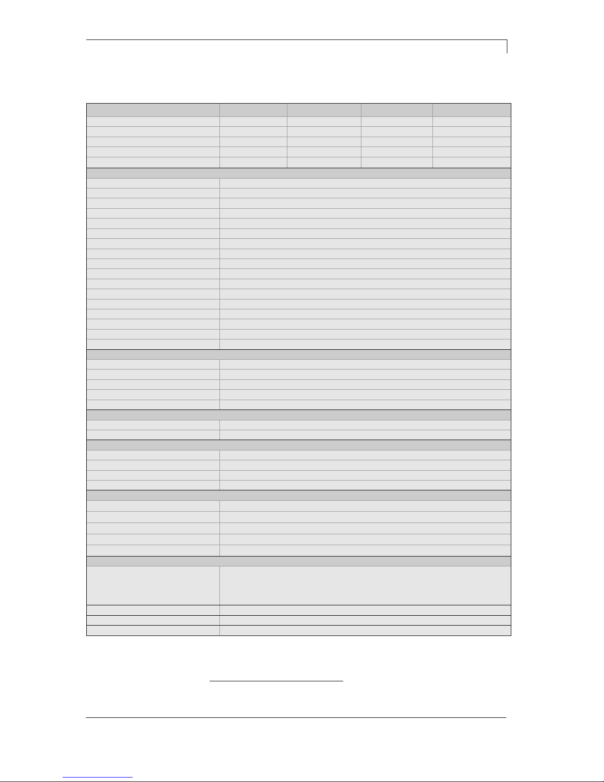
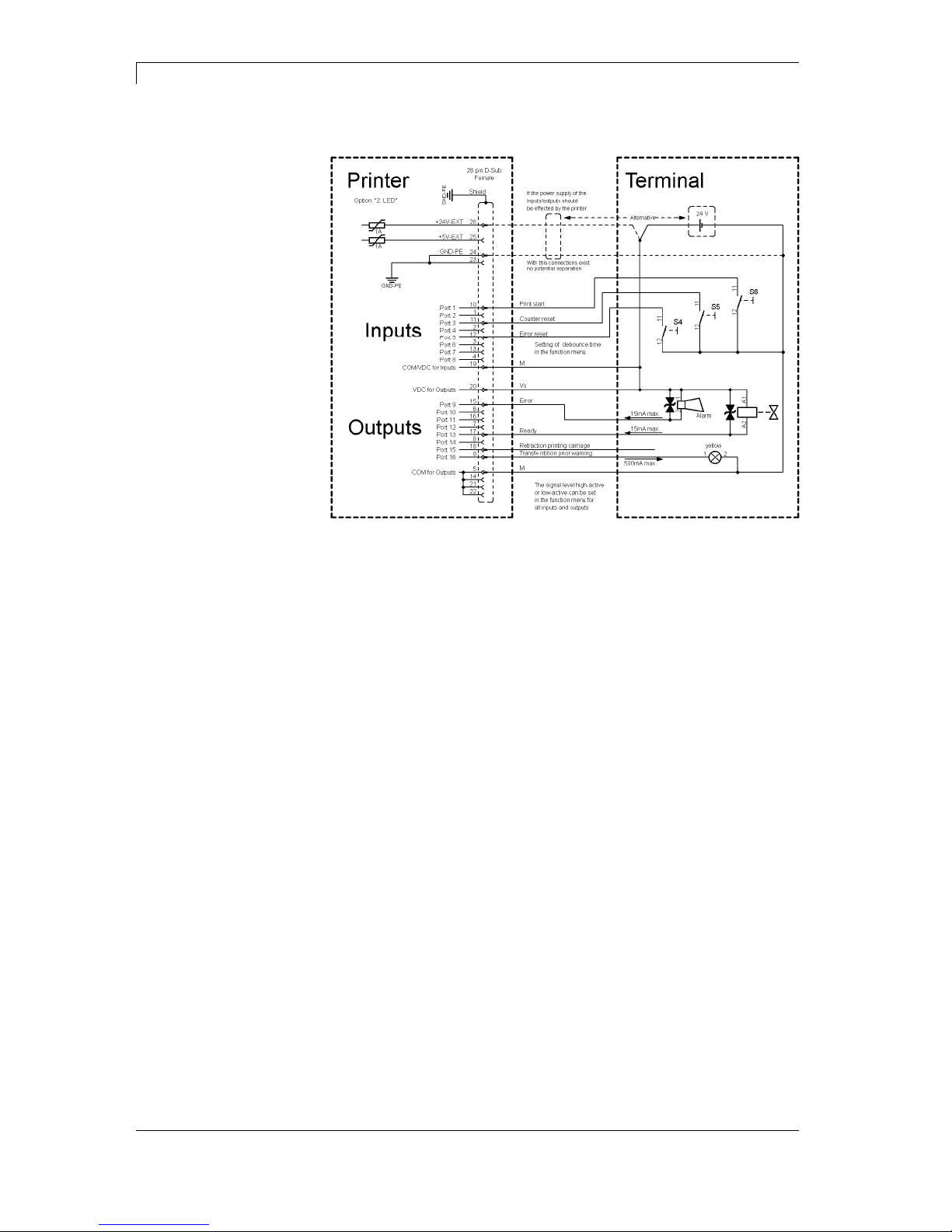
3.1 Control Inputs and Outputs
By means of a maximum of 16 control inputs and outputs which, in the
following, are also referred to as ports, different functions of the printer
system can be triggered and operating states can be displayed.
The ports are provided by means of a D-Sub bushing (26pin HD) at
the rear panel of the printer system and are galvanically isolated from
protective earth (PE) by means of an optocoupler semi-conductor
route.
Each port can be configured as input and as output. This function
however, is predefined in the printer software and cannot be changed
by the user.
The following parameters can be changed and set by using the menu:
debounce times and high or low active.
Figure 2
Printer, internal
circuitry
Pica II Series Technical Data
10.15 Operating Manual 17
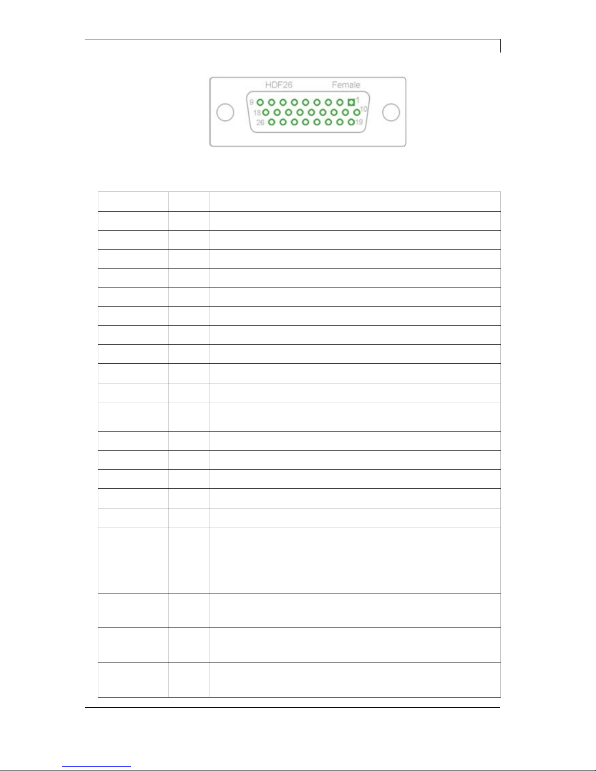
Figure 3
Port 1 to Port 16 = Assignment for I/O Profile 'Std_Label'
Identification Pin Description / Function
Port 1 10 Print start and cut (Input)
Port 2 1 Reprint last printed label (Input)
Port 3 11 Counter Reset (Input)
Port 4 2 No function
Port 5 12 Error reset (Input)
Port 6 3 No function
Port 7 13 No function
Port 8 4 No function
Port 9 15 Error (Output)
Port 10 6 Print order activ (Output)
Port 11 16 Dispenser photocell:
Label exists at dispenser photocell (Output)
Port 12 7 Single print (Output)
Port 13 17 Ready (Output)
Port 14 8 No function
Port 15 18 No function
Port 16 9 Prior warning for transfer ribbon end (Output)
COM/VDC
for Inputs
19 Common reference potential of all control inputs. 'COM/VDC for
Inputs' is usually connected with the (-) terminal of the control voltage
and the control inputs are switched to active (+).
By means of the option '2nd LED', 'COM/VDC for Inputs' can
optionally be connected with the (+) terminal of the control voltage.
Then, the control inputs are switched to active (-).
VDC for
Outputs
20 Common supply connection of all control outputs. 'VDC for Outputs'
must be connected with the (+) terminal of the control voltage.
Never leave 'VDC for Outputs' open even if no output is used.
COM for
Outputs
5,14
21,22
Common reference potential of all control outputs. 'COM for Outputs'
must be connected with the (-) terminal of the control voltage.
Never leave 'COM for Outputs' open even if no output is used.
GND-PE 23,24 'GND-PE' is the reference potential of the '+5 VDC EXT' and '+24
VDC EXT' voltages provided by the printer system.
'GND-PE' is printer internally connected with protective earth (PE).
Configuration of
D-Sub socket
Technical Data Pica II Series
18 Operating Manual 10.15
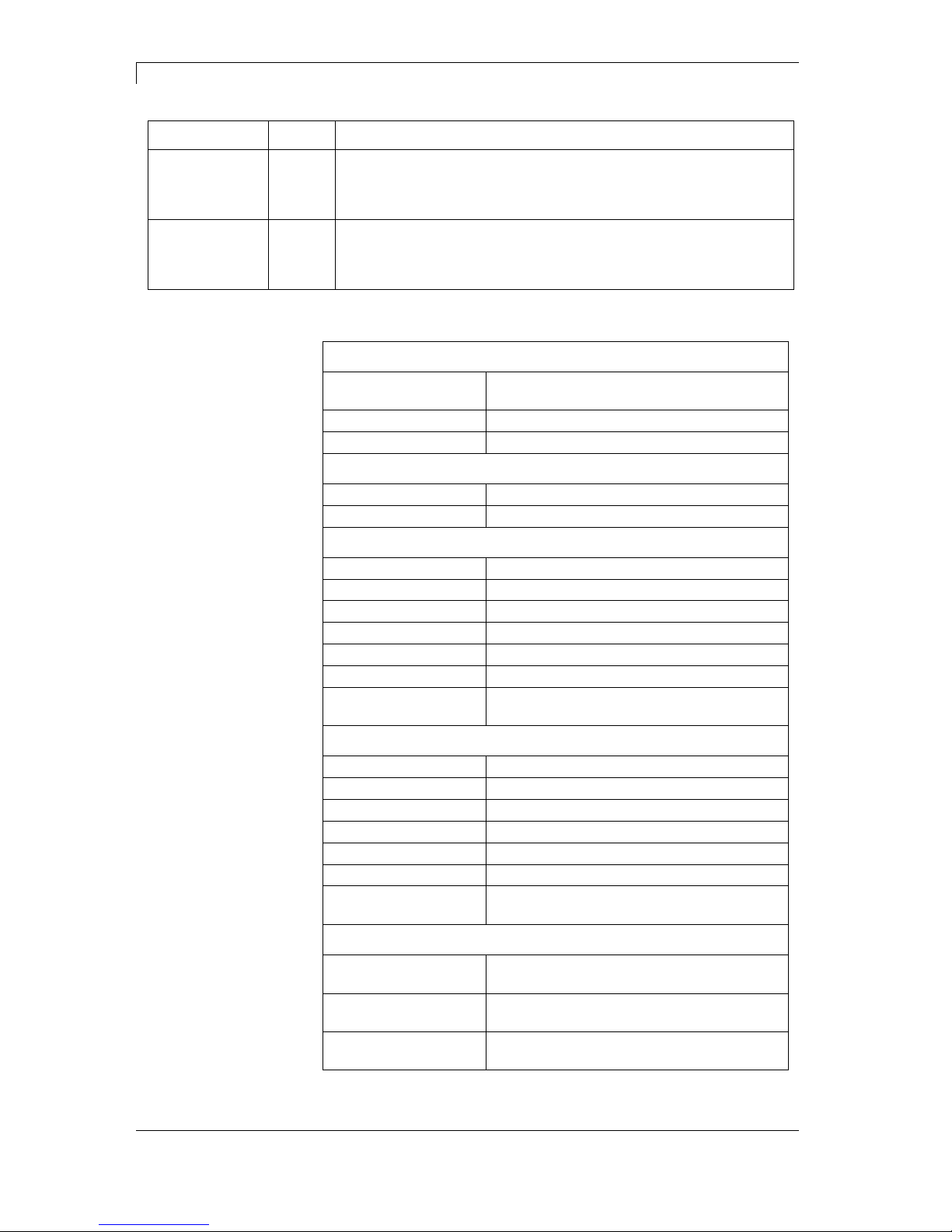
Identification Pin Description / Function
+ 5 VDC
EXT
25 5 Volt DC output for external use. Max. 1 A.
This voltage is provided from direct print module and can be used
e.g. as control voltage. Never apply any external voltage to this
output.
+ 24 VDC
EXT
26 24 Volt DC output for external use. Max. 1 A.
This voltage is provided from direct print module and can be used
e.g. as control voltage. Never apply any external voltage to this
output.
Plug Connector
Type D-Sub connector High Density
26-pin. / connector
Manufacturer W+P-Products
Reference number 110-26-2-1-20
Output Voltages (connected with GND-PE)
+ 24 V / 1 A Fuse: Polyswitch / 30 V / 1 A
+ 5 V / 1 A Fuse: Polyswitch / 30 V / 1 A
Port 1 - 15
Input
Tension 5 VDC … 24 VDC
Impedance 47Ω + (100nF || 10 kΩ)
Output
Tension 5 VDC … 24 VDC
Impedance 47Ω + (100nF || 10 kΩ || 47Ω)
Current max. High +15 mA
Low -15 mA
Port 16
Input
Tension 5 VDC … 24 VDC
Impedance 100nF || 10 kΩ
Output
Tension 5 VDC … 24 VDC
Impedance 100nF || 10 kΩ
Current max. High +500 mA (Darlington BCP56-16)
Low - 500 mA (Darlington BCP56-16)
Optocoupler
Output TCMT4106, CTR 100% - 300%, Vishay or
TLP281-4(GB), CTR 100% - 600%, Toshiba
Input TCMT4106, CTR 100% - 300%, Vishay or
TLP281-4(GB), CTR 100% - 600%, Toshiba
Input
Option 2nd LED
TCMT4600, CTR 80% - 300%, Vishay or
TLP280-4, CTR 33% - 300%, Toshiba
Technical data
Pica II Series Technical Data
10.15 Operating Manual 19
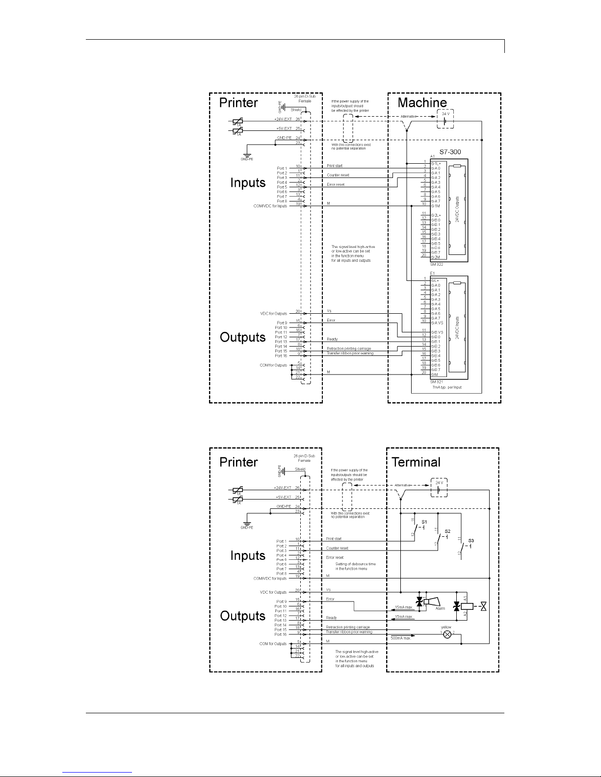
Device connection to a machine with S7-300 SPS.
Figure 4
Device connection to a operating panel.
Figure 5
Example 1
Example 2
Technical Data Pica II Series
20 Operating Manual 10.15
Device connection version if 'Option: 2. LED'.
Figure 6
When connecting a reed contact with a control input, the contact must
have a switching capacity of min. 1 A in order to prevent the contact
from sticking due to the inrush current. As an alternative, a suitable
resistor can be connected in series.
If one of the printer’s internal voltages '+5 VDC EXT' or '+24 VDC
EXT' is used, an external fuse e.g. 0.5 AF, should be additionally
installed to protect the printer electronics.
In the event of an inductive load, an antiparallel connected diode, for
instance, must be used to discharge the induction energy.
In order to minimise the influence of leakage currents at control
outputs, a resistor must, depending on what is connected, be installed
in parallel with the load.
In order to avoid any damages to the printing system, the max. output
currents must not be exceeded or outputs shorted.
Example 3
Precautions

Pica II Series Technical Data
10.15 Operating Manual 21
3.2 Plug & Play
Plug & Play capable printers can be recognised automatically at
parallel ports, USB-IEEE 1394- or infra-red connections but the last
both are not important for our printers.
The following table shows the Plug & Play capability of the different
operating systems.
Interface Windows
95 98 Me NT4 2000 XP Vista 7
LPT
Support
Recognition
by
Boot
Procedure,
Dev. Manager
Installation
USB
Support
s.b.
Recognition
by
Hot Plug
& Play
s.b. Hot Plug & Play
The table above shows that USB provides the recognition during the
connection in current operating mode, the so-called Hot-Plug & Play.
Depending on the operating system, for the parallel interface the
different possibilities are given:
Windows 95 / 98 / Me
Printers can be recognized during the starting procedure of
Windows or by the Search for new hardware by means of the
hardware wizard.
Windows 2000 / XP / Vista / 7
Printers can be recognized during the starting procedure of
Windows or by the Search for new hardware by means of the
hardware wizard or if the option 'Automatic recognition and
installation of Plug & Play printer' and/or 'Search automatically for
new hardware components and install' is activated.
NOTICE!
If a driver is installed outside of the Plug & Play
recognition, Windows reports at each restart that a new
printer was found. In this case, the driver is to be
installed anew by the Wizard. If the driver is certified for
Windows, the reinstallation is executed automatically.
NOTICE!
Windows NT 4.0 does not support USB devices. However,
some distributors offer drivers that support USB (without Plug
& Play). Such a driver which suits to our printer is offered from
BSQUARE. For more information, visit their web site:
www.bsquare.com or contact
BSQUARE Headquarters (USA)
888-820-4500
sales @bsquare.com
BSQUARE (Europe)
+49 (811) 600 59-0
europe@bsquare.com


Pica II Series Installation
10.15 Operating Manual 23
4 Installation
Lift the label printer out of the box.
Check the label printer for transport damages.
Check delivery for completeness.
Label Printer.
Power Cable.
Empty core, mounted on transfer ribbon rewinder.
Tear-off edge (basic printers only).
Dispenser edge (printers with option dispenser only).
Cutter unit (printers with option cutter only).
Documentation.
Printer driver on CD ROM.
Labelstar Office LITE on CD ROM
NOTICE!
Retain original packaging for subsequent transport.
4.1 Setting up the Label Printer
CAUTION!
The label printer and the print media can be damaged by
moisture and water.
Set up the label printer only in a dry place protected
from sprayed water.
Set up label printer on a level, vibration-free and air draught-free
surface.
Open cover of label printer.
Remove foam transportation safeguards near the printhead.
Unpack the
label printer
Scope of delivery

Installation Pica II Series
24 Operating Manual 10.15
4.2 Connecting the Label Printer
The label printer is equipped with an universal AC adaptor and is
operated according to standard with nominal voltage of 230 V.
The conversion to 115 V is only allowed by trained personnel.
CAUTION!
The label printer can be damaged by undefined switch-on
currents.
Set de power switch to '0' before plugging in the label
printer.
Insert power cable into power connection socket.
Insert plug of power cable into a grounded electrical outlet.
NOTICE!
Insufficient or missing grounding can cause faults during
operation.
Ensure that all computers and connection cables connected to
the label printer are grounded.
Connect label printer to computer or network with a suitable
cable.
4.3 Switching on the Label Printer
Once all connections have been made:
Switch label printer on with the power switch.
After switching on the label printer the main menu appears
which shows the current date and time.
Connection to the
power supply
Connecting to a
computer or
computer network

Pica II Series Installation
10.15 Operating Manual 25
4.4 Start-Up
NOTICE!
The printer can be controlled either by our printer driver or our
label design software.
After switching on the label printer the main menu appears which
shows the current status as well as current date and time.
Insert label material and transfer ribbon (see chapter 5., on page 27).
After inserting the labels and the transfer ribbon the labels must be
measured by the printer. With this procedure the label length is
measured and the label photocell adjusted.
Press keys
and on the foil keyboard (> 3 sec.) to start the
measuring process. For the measuring procedure the printer must be
in online mode.
After terminating the measuring procedure press key
to change to
the online mode.
NOTICE!
To enable correct measuring, at least two completed labels have
to be passed through (not for continuous labels).
During the measuring procedure of label and gap length small
differences can occur. Therefore the values can be set and
transferred to the printer by means of the label design software as well
as via the printer driver.


Pica II Series Loading Media
10.15 Operating Manual 27
5 Loading Media
5.1 Loading Label Roll
E
B
C
J
D
A
H
K
F
G
I
Figure 7
1. Open the printer cover.
2. Open printhead (K) by turning the red pressure lever (J)
anticlockwise.
3. Remove the outside label mounting plate (A).
4. Load the label roll with inner winding onto the unwinding roll (B).
5. Attach again the label mounting plate (A).
6. Lead the label material (H) below the return pulley (D) and the
printhead (K).
Make sure that the material is passed through the photocell (E).
7. Move the printhead (K) down by turning the red lever (J) in
clockwise direction until it locks.
8. Adjust the adjusting ring (C) on the deviating shaft (D) to the
material width.
9. Close the printer cover.
The printer is equipped by default with an integrated tear-off edge (not
with option cutter or dispenser).
For an operation with tear-off edge (I) unscrew the two knurled knobs
(F) and remove the front plate (G).
Loading label roll for
standard mode
Loading label roll for
tear-off mode

Loading Media Pica II Series
28 Operating Manual 10.15
E
B
C
G
D
A
H
F
J
I
Figure 8
1. Open the printer cover.
2. Open printhead (H) by turning the red pressure lever (G)
anticlockwise.
3. Remove the outside label mounting plate (A).
4. Load the label roll with inner winding onto the unwinding roll (B).
5. Attach again the label mounting plate (A).
6. Lead the label material below the return pulley (D) and the
printhead (H).
Make sure that the material is passed through the photocell (E).
7. Guide the label material over the pressure roll (F) and fix it with a
clamp (J) to the rewinding roll (I).
8. Move the printhead (H) down by turning the red lever (G) in
clockwise direction until it locks.
9. Adjust the adjusting ring (C) on the deviating shaft (D) to the
material width.
10. Close the printer cover.
Loading labels for
rewinding mode

Pica II Series Loading Media
10.15 Operating Manual 29
B
A
H
I
J
G
Figure 9
1. Open the printer cover.
2. Open printhead (J) by turning the red pressure lever (I)
anticlockwise.
3. Remove the outside label mounting plate (A).
4. Load the label roll with inner winding onto the unwinding roll (B).
5. Attach again the label mounting plate (A).
6. Lead the label material (I) below the return pulley (D) and the
printhead (J).
Make sure that the material is passed through the photocell (E).
7. Guide the label material through the bottom plate (F) and the
cutter ledge (H).
8. Move the printhead (J) down by turning the red lever (I) in
clockwise direction until it locks.
9. Adjust the adjusting ring (C) on the deviating shaft (D) to the
material width.
10. Close the printer cover.
Loading label roll
for cutting mode

Loading Media Pica II Series
30 Operating Manual 10.15
B
J
A
K
F
DCE
N
M
H
G
I
Figure 10
1. Open the printer cover.
2. Open printhead (K) by turning the red pressure lever (J)
anticlockwise.
3. Remove the outside label mounting plate (A).
4. Load the label roll with inner winding onto the unwinding roll (B).
5. Attach again the label mounting plate (A).
6. Lead the label material below the return pulley (C) and printhead
(K) and hold it towards the marked stopper surface (L).
Make sure that the material is passed through the photocell (E).
7. Move the printhead (K) down by turning the red lever (J) in
clockwise direction until it locks.
8. Adjust the adjusting ring (D) on the deviating shaft (C) to the
material width.
9. Press key
to start a test print, or press keys + to start
a measuring procedure to determine the exact position of label
beginning.
Loading label roll
fop peel-off mode

Pica II Series Loading Media
10.15 Operating Manual 31
10. Unlock the dispense roll (H) by pressing the red locking part (G).
11. Strip some labels from the backing paper and lead the backing
material over the dispenser edge (I).
12. Press the dispense roll (H) backwards towards the backing paper.
13. Place the backing material under the dispense angle (F)
rearwards and fix it with the clamp (N) at the optional external
rewinding unit (M).
14. Close the printer cover.

Loading Media Pica II Series
32 Operating Manual 10.15
5.2 Loading Fan-Fold Labels
D
E
F
AC B
Figure 11
1. Open the printer cover.
2. Open printhead (F) by turning the red pressure lever (E)
anticlockwise.
3. Place the fan-fold material (A) from behind to the printer bottom.
4. Lead the fan-fold material (A) below the return pulley (C) and the
printhead (F).
Make sure that the material is passed through the photocell (D).
5. Move the printhead (F) down by turning the red lever (E) in
clockwise direction until it locks.
6. Adjust the adjusting ring (B) on the deviating shaft (C) to the
material width.
7. Close the printer cover.

Pica II Series Loading Media
10.15 Operating Manual 33
5.3 Loading Transfer Ribbon
NOTICE!
For the thermal transfer printing method it is necessary to load a
ribbon, otherwise when using the printer in direct thermal print it
is not necessary to load a ribbon. The ribbons used in the printer
have to be at least the same width as the print media. In case the
ribbon is narrower than the print media, the printhead is partly
unprotected and this could lead to early wear and tear.
C
D
AEB
Figure 12
NOTICE!
Before a new transfer ribbon roll is loaded, the printhead must be
cleaned using printhead and roller cleaner (97.20.002). For
detailed information, please see page 49.
The handling instructions for the use of Isopropanol (IPA) must
be observed. In the case of skin or eye contact, immediately
wash off the fluid thoroughly with running water. If the irritation
persists, consult a doctor. Ensure good ventilation.
1. Open the printer cover.
2. Open printhead (C) by turning the red pressure lever (D)
anticlockwise.
3. Load the transfer ribbon roll (A) with outer winding onto the
unwinding roll (B).
4. Place an empty ribbon roll on the rewinding roll (E) and lead the
transfer ribbon below the printhead (C).
5. Fix the transfer ribbon with an adhesive tape at the empty core of
the rewinding roll (E). Make sure that the rotation direction of
transfer ribbon rewinding is anticlockwise.

Loading Media Pica II Series
34 Operating Manual 10.15
6. Move the printhead (C) down by turning the red lever (D) in
clockwise direction until it locks.
7. Close the printer cover.
NOTICE!
As for the electrostatic unloading the thin coating of the thermal
printhead or other electronic parts can be damaged, the transfer
ribbon should be antistatic.
The use of wrong materials can lead to printer malfunctions and
the guarantee can expire.

Pica II Series Control Panel
10.15 Operating Manual 35
6 Control Panel
6.1 Structure of the Control Panel
With the control panel the user can control the operation of the printer.
The following processes can be done:
Interrupt, continue or cancel print orders.
Test functions.
Determine label values.
Error acknowledgement.
Restore default values.
Settings made on the control panel make generally the basic settings
of the label printer.
6.2 Printer States
NOTICE!
The printer has additionally to the two-line display 2 coloured
LEDs so that the user can read the printer state from the
distance.
State
LED
Display Description
Ready
ONLINE
Date and time
The printer is ready and can receive
data
Not ready
OFFLINE
Date and time
In Offline mode the following processes
can be done:
Feeds a blank label
Test print / status print
Error acknowledgement
Cancel a print order
Printing
Name Print
Name of the printed
label.
Specified and actual
number of prints
inside a current print
order.
The printer is processing the current
print order.
The printer can receive data for a new
print order.
The new print order will start after the
previous one has finished.

Control Panel Pica II Series
36 Operating Manual 10.15
State LED Display Description
Pause
Name Stopped
Name of the printed
label.
Specified and actual
number of prints
inside a current print
order.
The print order was interrupted by the
user.
Waiting
Name Waiting
Name of the printed
label.
Specified and actual
number of prints
inside a current print
order.
Only with option dispenser:
The printer is ready to print the next
label of the current print order and to
dispense it afterwards.
Error
Error Number
Error number
Short-description of
the error.
An error is occurred that must be
rectified (see error table on page 53).
The print order can be continued after
removing the error.
6.3 Key Functions
NOTICE!
The key functions depend on the current printer state.
State Key Description/Function
Ready
Change to the offline mode.
+
Keep the keys successively pressed to determine the
label values.
+
Keep the keys successively pressed (> 10 s) to restore
the default values.

Pica II Series Control Panel
10.15 Operating Manual 37
State Key Description/Function
Not ready
Change to the online mode.
Short press = Label feed.
Longer press = Single cut.
Short press = Test print.
Longer press = Status print.
+
Keep the keys together pressed to access the service
functions (page 43).
Printing
Interrupt print order.
Continue print order.
Pause
Interrupt print order.
Continue print order.
Error
Error acknowledgement
(see table on page 53).


Pica II Series Printing
10.15 Operating Manual 39
7 Printing
CAUTION!
Printhead damage caused by improper handling!
Do not touch the underside of the printhead with the
fingers or sharp objects.
Ensure that the labels are clean.
Ensure that the label surfaces are smooth. Rough
labels act like emery paper and reduce the service life
of the printhead.
Print with the lowest possible printhead temperature.
7.1 Processing Print Orders
The printer must be in Online mode.
During a current print order the printer is in Online mode, i.e. data can
be sent by the interface.
Send the print order by interface to the printer.
After transferring the data the print order is started automatically and
the first label is printed.
Press key
to interrupt the print order.
Press key
to print the last printed label again.
This is relevant if an error appeared during the current print order and
the sequence of labels (e.g. counter) is considerably important.
Press key
to continue the print order.
Press key
to cancel the interrupted print order.
7.2 Status Print
The printer must be in Online mode.
Press key
(> 2 s) to print the current printer settings and a sample
label.
The printer settings can be modified only by the interface.

Printing Pica II Series
40 Operating Manual 10.15
7.3 Label Feed
The printer must be in Offline mode.
Press key
to start the feed of one label.
7.4 Saving Labels
The saving of data e.g. text or graphic is done in the internal data
memory. The saving can be selected either in our label design
software or by an appropriate program.
For more information, see the appropriate manual.
7.5 Tear-off Mode
In order to detach the label band after terminating the print order by
hand, the label printer is equipped by default with a tear-off bar.
Loading of labels in tear-off mode, see on page 27.
7.6 Synchronization of Label Feed
The printer must be in Offline mode.
After inserting the label material for dispenser or cutter mode, the
synchronization of label feed is necessary. The first label which is
detected by the label photocell will be transported to the print position
and all labels in front will be fed out of the printer.
The synchronization in dispenser mode prevents that blank labels are
peeled-off together with the first printed label.
The synchronization of label feed in cutter mode prevents that the first
cut label would be too long.
Press key
to start the synchronization.
Remove the labels peeled-off.

Pica II Series Printing
10.15 Operating Manual 41
7.7 Dispenser Mode
The label dispenser unit removes the label from backing paper and
provides it for further processing. After removing the label, the
following print order is activated by the dispenser photocell or an
external impulse to the dispenser inputs. The backing paper can be
rolled up again with the internal rewinder.
Loading of labels in peel-off mode, see on page 30.
NOTICE!
The operating mode can be selected in the printer driver or
our label design software.
Off:
It is printed without the labels are dispensed.
I/O static:
The input signal evaluated, i.e. it is printed as long as the signal
exists. The number of labels which was entered at the print start is
printed.
The set dispenser offset is not taken into consideration.
I/O static continuous:
For description of this operating mode, see I/O static.
Continuous means that it is printed as long as new data is transferred
via interface
The set dispenser offset is not taken into consideration.
I/O dynamic:
The external signal is evaluated dynamically, i.e. is the printer in
'waiting' mode a single label is printed at each signal changing. After
the print the set dispenser offset is executed, i.e. a backfeed is
effected.
I/O dynamic continuous:
For description of this operating mode, see I/O dynamic.
Continuous means that it is printed as long as new data is transferred
via interface.
Photocell:
The printer is controlled via photocell. The printer prints automatically
a label if the user takes away the label at the dispensing ledge. The
print order is finished when the target number of labels is reached.
Photocell continuous:
For description of this operating mode, see Photcell.
Continuous means that it is printed as long as new data is transferred
via interface.
Operating modes

Printing Pica II Series
42 Operating Manual 10.15
7.8 Cutter Mode
CAUTION!
Risk of injury, particularly during maintenance, the cutter blades are
sharp!
Switch off the before attaching the cutter!
The cutter may only be used when it is mounted on the printer!
Do not try to cut any materials which exceed the maximum
width or thickness specifications.
Do NOT touch the area of the moving blades!
The 'Guillotine' cutter permits cutting of materials up to a weight of
220 g/m² without any problems. The cutter can be refit without any
technical effort. The activation of a cut can be started by an external
impulse of the dispenser photocell.
Loading of labels in cutter mode, see on page 29.
NOTICE!
The operating mode can be selected in the printer driver or
our label design software.
Off:
The print order is processed without cutting.
Without Backfeed:
A cut is effected after each label.
We recommend using this operating mode if no data which is to print
is in the upper part of the label.
With Backfeed:
A cut is effected after each label.
Interval with Final Cut:
A cut is effected after a fixed number of labels which you have to enter
at the print start and additionally at the end of the print order.
Interval without Final Cut:
A cut is effected after a fixed number of labels which you have to enter
at the print start. At the end of the printer order no cut is effected
except when the set interval comes to the end of the print order.
Final Cut:
A cut is only effected at the end of the print order.
Single Cut:
The printer must be in Offline mode, then press key
(> 2 s).
Operating modes

Pica II Series Service Functions
10.15 Operating Manual 43
8 Service Functions
The printer must be in Offline mode.
Press and hold the keys
+ (> 3 s) to access the service
functions.
Adjust Sensibility of Label Photocell
Reflexion / Transmission Photocell - depending on setting
Press keys
+ to reduce the value.
Press keys
+ to increase the value.
Press key
to confirm the setting.
Determine signal threshold
Setting the photocell level.
In case of problems while positioning or measuring of label, levels for
label photocell can be set manually. Make sure that a large hub as
possible (label >3 V, gap <1 V) is set.
Press key
to arrive the next menu.
Adjust Sensibility of Dispenser Photocell
Press keys + to reduce the value.
Press keys
+ to increase the value.
Press key
to confirm the setting.
Press key
to arrive the next menu.
Adjust Heater Resistance
To achieve a high print quality, the indicated Ohm value must be set
after an exchange of printhead.
Press keys
+ to reduce the value.
Press keys
+ to increase the value.
Press key
to confirm the setting.
Lbl-PC TR S.[V]
19 4.65
Disp.-PC S.[V]
80 0.02
Heater Resist.
1250

Service Functions Pica II Series
44 Operating Manual 10.15
Press key
to arrive the next menu.
Select Printer Language
Press keys
+ or + to select the printer language.
The following languages are available: German, English, French,
Spanish, Finnish, Czech (option), Portuguese, Dutch, Italian, Danish
and Polish.
Press key
to confirm the selection.
Press key
to arrive the next menu.
Select Printer Emulation
Press keys + or + to change the protocol.
Change between CVPL protocol and ZPL II
®
protocol.
CVPL: Carl Valentin Programming Language
ZPL: Zebra
®
Programming Language
Press key
to confirm the selection.
The printer performs a restart and ZPL II
®
commands are transformed
into CVPL commands internally by the printer and then executed by
the printer.
NOTICE!
Before starting a firmware update make sure that the CVPL
protocol is selected.
Press key
to arrive the next menu.
Zero point adjustment in Y direction
Indication of value in 1/100 mm.
After replacing the printhead - the print cannot be continued at the
same position on the label, the difference can be corrected in printing
direction.
NOTICE!
The value for zero point adjustment is set ex works. After
replacing the printhead, only service personnel are allowed to
set this value anew.
Printer language
English
Printer emulat.
CVPL
ZP Y-Adjust
0.0

Pica II Series Service Functions
10.15 Operating Manual 45
Press key
to arrive the next menu.
Zero point adjustment in Y direction
Indication of value in 1/100 mm.
After replacing the printhead - the print cannot be continued at the
same position on the label, the difference can be corrected across the
printing direction.
NOTICE!
The value for zero point adjustment is set ex works. After
replacing the printhead, only service personnel are allowed to
set this value anew.
Press key
to arrive the next menu.
Select Printer Type
Press keys
+ or + to change the printer type.
Press key
to confirm the selection.
Press key
to arrive the next menu.
Printhead Type
Indication of the currently used printhead.
ZP X-Adjust
0.0
Printer type
Pica II 106/12
Printhead
PH 232


Pica II Series Maintenance and Cleaning
10.15 Operating Manual 47
9 Maintenance and Cleaning
DANGER!
Risk of death by electric shock!
Disconnect the label printer from power supply
before performing any maintenance work.
NOTICE!
When cleaning the label printer, personal protective
equipment such as safety goggles and gloves are
recommended.
Maintenance Task Frequency
General cleaning (see 9.1, on
page 48).
As necessary.
Cleaning print roller (see 9.1, on
page 48).
Each time the label roll is
changed or when the printout and
label transport are adversely
affected.
Cleaning printhead (see 9.3, on
page 49).
Direct thermal printing:
Each time the label roll is
changed.
Thermal transfer printing:
Each time the transfer ribbon is
changed or when the printout is
adversely affected.
Cleaning label photocell (see
9.4, on page 50).
When exchanging the label roll.
Replacing printhead (see 9.5,
on page 51).
In case of errors in printout.
NOTICE!
The handling instructions for the use of Isopropanol (IPA)
must be observed. In the case of skin or eye contact,
immediately wash off the fluid thoroughly with running
water. If the irritation persists, consult a doctor. Ensure
good ventilation.
WARNING!
Risk of fire by easily inflammable label soluble!
When using label soluble, dust must be completely
removed from the label printer and cleaned.
Maintenance
schedule

Maintenance and Cleaning Pica II Series
48 Operating Manual 10.15
9.1 General Cleaning
CAUTION!
Abrasive cleaning agents can damage the label printer!
Do not use abrasives or solvents to clean the outer
surface of the label printer.
Remove dust and paper fuzz in the printing area with a soft
brush or vacuum cleaner.
Clean outer surfaces with an all-purpose cleaner.
9.2 Cleaning the Print Roller
A soiled print roller can lead to reduced print quality and can affect
transport of material.
CD
B
A
Figure 13
1. Open the printer cover.
2. Turn red lever (B) counter clockwise to lift up the printhead (A).
3. Remove labels and transfer ribbon form the label printer.
4. Remove deposits with roller cleaner and a soft cloth.
5. Turn the roller (C + D) manually step by step to clean the
complete roller (only possible when printer is switched off, as
otherwise the step motor is full of power and the roller is kept in its
position).

Pica II Series Maintenance and Cleaning
10.15 Operating Manual 49
9.3 Cleaning the Printhead
Printing can cause accumulation of dirt at printhead e.g. by colour
particles of transfer ribbon, and therefore it is necessary to clean the
printhead in regular periods depending on operating hours,
environmental effects such as dust etc.
CAUTION!
Printhead can be damaged!
Do not use sharp or hard objects to clean the
printhead.
Do not touch protective glass layer of the printhead.
Figure 14
1. Open the printer cover.
2. Turn red lever (B, in Figure 13) counter clockwise to lift up the
printhead.
3. Remove labels and transfer ribbon from the label printer.
4. Clean printhead surface with special cleaning pen or a cotton
swab dipped in pure alcohol.
5. Allow printhead to dry for 2-3 minutes before commissioning the
printer.

Maintenance and Cleaning Pica II Series
50 Operating Manual 10.15
9.4 Cleaning the Label Photocell
CAUTION!
Label photocell can be damaged!
Do not use sharp or hard objects or solvents to clean
the label photocell.
The label photocell can become dirtied with paper dust and this can
adversely affect label detection.
Figure 15
1. Open printer cover.
2. Turn red lever counter clockwise to lift up the printhead.
3. Remove labels and transfer ribbon from the label printer.
4. Blow out the photocell (A) with pressure gas spray.
Observe strictly the instructions on the spray can!
5. Clean the label photocell (A) additionally with a cleaning card (B)
before soaked in pure alcohol. Move the cleaning card from one
side to the other (see illustration).
6. Reload the labels and transfer ribbon (see chapter 5 Loading
Media, on page 27).

Pica II Series Maintenance and Cleaning
10.15 Operating Manual 51
9.5 Replacing the Printhead (General)
NOTICE!
The printhead (D) is preinstalled on a head plate (A) and
aligned at the factory.
E D
C
G
BA
F
Figure 16
A Head plate
B Plug connection signal
C Plug connection tension
D Printhead
E Focal line
F Guiding
G Screw
CAUTION!
The printhead can be damaged by static electricity
discharges and impacts!
Set up printer on a grounded, conductive surface.
Ground your body, e.g. by wearing a grounded
wristband.
Do not touch contacts on the plug connections (B,
C).
Do not touch printing line (E) with hard objects or
your hands.

Maintenance and Cleaning Pica II Series
52 Operating Manual 10.15
9.6 Replacing the Printhead
D
C
B
A
Figure 17
1. Remove labels and transfer ribbon from the label printer.
2. When printhead is closed, loosen the fixing screw (B).
3. Turn red lever (D) counter clockwise to lift up the printhead.
4. If the printhead (E) is not disengaged on the pressure roller,
continue loosen the fixing screw (B).
5. Remove the printhead carefully to the front until you can reach the
plug connections.
6. Remove plug connections and then remove printhead (E).
7. Loosen fixing screws (G) and remove guiding (H).
Attach plug connections.
1. Mount guiding (H) and fixing screws (G) at the printhead.
2. Position printhead in printhead mounting bracket in such a way
that the pins are secured in the corresponding holes in the head
plate.
3. Lightly keep printhead mounting bracket on the printer roller with
one finger and check for correct positioning of the printhead.
4. Screw in fixing screw (B) and tighten it.
5. Reload the labels and transfer ribbon (see chapter 5 Loading
Media, on page 27).
6. Check resistance value on the type plate of printhead and if
necessary change the value in the menu Service functions/Heater
resistance.
Removing the
printhead
Installing the
printhead

Pica II Series Maintenance and Cleaning
10.15 Operating Manual 53
9.7 Adjusting the Printhead
Complete the following printhead settings to achieve the best possible
print image:
Align the heating line with the highest point of the print roller.
Density of the print image is the greatest at this point.
Set the parallelism of horizontal lines with the edge of the label.
CAUTION!
The printhead assembly can be damaged.
Attempting to adjust the printhead when the fixing screw (E) is
tight can lead to defects at the printhead assembly.
Always loosen the fixing screw (E) before adjusting the
printhead.
NOTICE!
Open and close the printhead locking device after each step of
the adjustment.
A
B
CDEF
Figure 18

Maintenance and Cleaning Pica II Series
54 Operating Manual 10.15
An important characteristic for a high quality print is the parallelism of
the focal line of the thermal printhead to the pressure roll. Because of
the fact that the position of focal line of the printhead depends on
fluctuations caused by production, it is necessary to adjust the
parallelism.
1. Loosen the fixing screw (E) approx. ¼ rotations.
2. Adjust the parallelism with the adjusting screws (C+F)
Clockwise = printhead moves forwards
Counter clockwise = printhead moves backwards
3. Adjust the parallelism as long as the printing result comes up to
your full expectation.
4. Tighten again the fixing screws (E).
5. Start a print order with approx. 10 labels and control the correct
passage of transfer ribbon.
Increasing the head contact pressure leads to an improvement of the
print image density on the corresponding side and to a shifting of the
ribbon feed path in the corresponding direction.
CAUTION!
Damage of printhead by unequal use!
Change factory settings only in exceptional cases.
The selection of the smallest value can optimise the life cycle of
printhead.
1. Turn the pressure pieces (A+B, Fehler! Verweisquelle konnte
nicht gefunden werden.) to change the pressure of printhead.
2. Turning the pressure pieces
in clockwise direction increases the pressure
anticlockwise reduces the pressure.
3. Tighten again the pressure lever clockwise to lock the printhead.
Parallelism
Pressure

Pica II Series Error Correction
10.15 Operating Manual 53
10 Error Correction
In case an error occurred the printer stops and the print order is
interrupted.
After removing the error, press key
to acknowledge the error.
An active print order is now interrupted. Press key
to print the last
printed label once more.
This is particularly important if an error arose during a current print
order and the sequence of the labels (e.g. counter) is to be
considered.
Press key
to continue a print order or press key to cancel the
print order.
Error message Cause Remedy
1 Line too high
Line rises up completely or
partly over the upper edge of
label.
Move line down (increase Y
value).
Check rotation and font.
2 Line too low
Line rises up completely or
partly over the bottom edge of
label.
Move line up (reduce X value).
Check rotation and font.
3 Character set
One res. several characters of
the text is res. are not available
in the selected font.
Change text.
Change font.
4 Unknown code type
Selected code is not available. Check code type.
5 Unvalid position
Selected position is not
available.
Check position.
6 CV font
Selected font is not available. Check font.
7 Vector font
Selected font is not available. Check font.
8 Measuring label
While measuring no label was
found.
Set label length is too large.
Check label length and if labels
are inserted correctly.
Restart measuring anew.
9 No label found
No label available.
Soiled label photocell.
Labels not inserted correctly.
Insert new label roll.
Check if labels are inserted
correctly.
Clean the label photocell.
10 No ribbon
During the print order the
ribbon roll becomes empty
(front printhead).
Defect at the transfer ribbon
photocell (front photocell).
Change transfer ribbon.
Check transfer ribbon photocell
(service functions).
11 COM FRAMING
Stop bit error. Check stop bits.
Check baud rate.
Check cable (printer and PC).

Error Correction Pica II Series
54 Operating Manual 10.15
Error message Cause Remedy
12 COM PARITY
Parity error. Check parity.
Check baud rate.
Check cable (printer and PC).
13 COM OVERRUN
Loss of data at serial interface
(RS-232).
Check baud rate.
Check cable (printer and PC).
14 Field numer
Received line number is invalid
at RS-232 and Centronics.
Check sent data.
Check connection PC - printer.
15 Length mask
Invalid length of received mask
statement.
Check sent data.
Check connection PC - printer.
16 Unknown mask
Transferred mask statement is
invalid.
Check sent data.
Check connection PC - printer.
17 Missing ETB
No end of data found. Check sent data.
Check connection PC - printer.
18 Invalid character
One res. several characters of
the text is res. are not available
in the selected font.
Change text.
Change font.
19 Invalid statement
Unknown transferred data
record.
Check sent data.
Check connection PC - printer.
20 Invalid check digit
For check digit control the
entered res. received check
digit is wrong.
Calculate check digit anew.
Check code data.
21 Invalid SC number
Selected SC factor is invalid for
EAN res. UPC.
Check SC factor.
22 Invalid number of
digits
Entered digits for EAN res.
UPC are invalid
< 12; > 13.
Check number of digits.
23 Check digit
calculation
Selected check digit calculation
is not available in the bar code.
Check calculation of check
digit.
Check bar code type.
24 Invalid extension
Selected zoom factor is not
available.
Check zoom factor.
25 Offset sign
Entered sign is not available. Check offset value.
26 Offset value
Entered offset value is invalid. Check offset value.
27 Printhead
temperature
Printhead temperature is too
high.
Defective printhead sensing
device.
Reduce contrast.
Change printhead.
28 Cutter error
With cut an error occurred.
Paper jam.
Check label run.
Check cutter run.
29 Invalid parameter
Entered data do not correspond
to the characters allowed from
the application identifier.
Check code data.
30 Application
Identifier
Selected application identifier is
not available in GS1-128.
Check code data.
31 HIBC definition
F Missing HIBC system sign.
Missing primary code.
Check definition of HIBC code.

Pica II Series Error Correction
10.15 Operating Manual 55
Error message Cause Remedy
32 System clock
Real Time Clock function is
selected but the battery is
empty.
Defective RTC.
Change battery.
Change RTC component.
33 No CF interface
Interrupted connection CPU CF card.
Defective CF card interface.
Check connection CPU - CF
card interface.
Check CF card interface.
34 No print memory
No print CF found. Check CF assembly on CPU.
35 Cover open
At start of a print order the
printhead is open.
Close the printhead and start
print order anew.
36 BCD invalid format
BCD error
Invalid format for the
calculation of Euro variable.
Check entered format.
37 BCD overflow
BCD error
Invalid format for the
calculation of Euro variable.
Check entered format.
38 BCD division
BCD error
Invalid format for the
calculation of Euro variable.
Check entered format.
39 FLASH ERROR
Flash component error. Run a software update.
Change CPU.
40 Length command
Invalid length of the received
command statement.
Check data sent.
Check connection PC - printer.
41 No drive
CF card not found / not
correctly inserted.
Insert CF card correctly.
42 Drive error
Impossible to read CF card
(faulty).
Check CF card, if necessary
change it.
43 Not formatted
CF Card not formatted. Format CF card.
44 Delete current
directory
Attempt to delete the actual
directory.
Change directory.
45 Path too long
Too long indication of path. Indicate a shorter path.
46 Drive write-
protected
Memory card is write-protected. Deactivate write protection.
47 Directory not file
Attempt to indicate a directory
as file name.
Correct your entry.
48 File already open
Attempt to change a file during
an access is active.
Select another file.
49 No file/directory
File does not exist on CF card. Check file name.
50 Invalid file name
File name contains invalid
characters.
Correct entry of name, remove
special characters.

Error Correction Pica II Series
56 Operating Manual 10.15
Error message Cause Remedy
51 Internal file error
Internal file system error. Please contact your distributor.
52 Root full
The max. number (64) of main
directory entries is reached.
Delete at least one main
directory entry and create
subdirectories.
53 Drive full
Maximum CF capacity is
reached.
Use new CF Card, delete no
longer required files.
54 File/directory
exists
The selected file/directory
already exists.
Check name, select a different
name.
55 File too large
During copying procedure not
enough memory space onto
target drive available.
Use a larger target card.
56 No update file
Errors in update file of
firmware.
Start update file anew.
57 Invalid graphic file
The selected file does not
contain graphic data.
Check file name.
58 Directory not empty
Attempt to delete a not empty
directory.
Delete all files and subdirectories in the desired
directory.
59 No interface
No CF card drive found. Check connection of CF card
drive.
Contact your distributor
60 No CF card
No CF card is inserted. Insert CF card in the slot.
61 Webserver error
Error at start of web server. Please contact your distributor.
62 Wrong FPGA
The direct print module is
equipped with the wrong
FPGA.
Please contact your distributor.
63 End position
The label length is too long.
The number of labels per cycle
is too much.
Check label length res. the
number of labels per cycle.
64 Zero point
Defective photocell. Change photocell.
65 Compressed air
Pressure air is not connected. Check pressure air.
66 External releaser
External print release signal is
missing.
Check input signal.
67 Row too long
Wrong definition of column
width res. number of columns.
Reduce the column width res.
correct the number of columns.
68 Scanner
The connected bar code
scanner signals a device error.
Check the connection
scanner/printer.
Check scanner (dirty).
69 Scanner NoRead
Bad print quality.
Printhead completely soiled or
defective.
Print speed too high.
Increase contrast.
Clean printhead or exchange (if
necessary).
Reduce print speed.
70 Scanner data
Scanned data does not
correspond to the data which is
to print.
Exchange printhead.

Pica II Series Error Correction
10.15 Operating Manual 57
Error message Cause Remedy
71 Invalid page
As page number either 0 or a
number > 9 is selected.
Select a number between 1
and 9.
72 Page selection
A page which is not available is
selected.
Check the defined pages.
73 Page not defined
The page is not defined. Check the print definition.
74 Format user guiding
Wrong format for customised
entry.
Check the format string.
75 Format date/time
Wrong format for date/time. Check the format string.
76 Hotstart CF
No CF card found. If option hotstart was activated,
a CF card must be inserted.
Switch off the printer before
inserting the memory card.
77 Flip/Rotate
Selection of print of several
columns and also mirror/rotate.
It is only possible to select one
of both functions.
78 System file
Loading of temporary hotstart
files.
Not possible.
79 Shift variable
Faulty definition of shift times
(overlapping times).
Check definition of shift times.
80 GS1 Databar
General GS1 Databar error. Check definition and parameter
of GS1 Databar code.
81 IGP error
Protocol error IGP. Check sent data.
82 Time generation
Printing creation was still active
at print start.
Reduce print speed.
Use printers' output signal for
synchronisation.
Use bitmap fonts to reduce
generating time.
83 Transport protection
Both DPM position sensors
(start/end) are active.
Displace zero point sensor
Check sensors in service
functions menu
84 No font data
Font and web data is missing. Run a software update.
85 No layout ID
Label ID definition is missing. Define label ID onto the label.
86 Layout ID
Scanned data does not
correspond to defined ID.
Wrong label loaded from CF
card.
87 RFID no label
RFID unit cannot recognise a
label.
Displace RFID unit or use an
offset.
88 RFID verify
Error while checking
programmed data.
Faulty RFID label.
Check RFID definitions
89 RFID timeout
Error at programming the RFID
label.
Label positioning.
Faulty label.
90 RFID data
Faulty or incomplete definition
of RFID data.
Check RFID data definitions.
91 RFID tag type
Definition of label data does not
correspond with the used label.
Check storage partitioning of
used label type

Error Correction Pica II Series
58 Operating Manual 10.15
Error message Cause Remedy
92 RFID lock
Error at programming the RFID
label (locked fields).
Check RFID data definitions.
Label was already
programmed.
93 RFID programming
Error at programming the RFID
label.
Check RFID definitions.
94 Scanner timeout
The scanner could not read the
bar code within the set timeout
time.
Defective printhead.
Wrinkles in transfer ribbon.
Scanner wrong positioned.
Timeout time too short.
Check printhead.
Check transfer ribbon.
Position scanner correctly,
corresponding to the set
feeding.
Select longer timeout time.
95 Scanner layout
difference
Scanner data does not
correspond to bar code data.
Check adjustment of scanner.
Check scanner settings /
connection.
96 COM break
Serial interface error. Check settings for serial data
transmission as well as cable
(printer-PC).
97 COM general
Serial interface error. Check settings for serial data
transmission as well as cable
(printer-PC).
98 No software
printhead FPGA
No printhead-FPGA data
available.
Please contact your
responsible distributor.
99 Load software
printhead FPGA
Error when programming
printhead-FPGA.
Please contact your
responsible distributor.
100 Upper position
Sensor signal up is missing
(option APL 100).
Check input signals /
compressed-air supply.
101 Lower position
Sensor signal down is missing
(option APL 100).
Check input signals /
compressed-air supply.
102 Vacuum plate empty
Sensor does not recognise a
label at vacuum plate
(option APL 100).
Check input signals /
compressed-air supply.
103 Start signal
Print order is active but device
not ready to process it.
Check start signal.
104 No print data
Print data outside the defined
label.
Selection of wrong module type
(design software).
Check selected module type.
Check selection of left/right
version.
105 Printhead
No original printhead is used. Check the used printhead.
Contact your distributor.
106 Invalid Tag type
Wrong Tag type.
Tad data do not match the Tag
type in the printer.
Adapt data or use the correct
Tag type.
107 RFID invalid
RFID module is not activated.
No RFID data can be
processed.
Activate RFID module or
remove RFID data from label
data.

Pica II Series Error Correction
10.15 Operating Manual 59
Error message Cause Remedy
108 GS1-128 invalid
Transferred GS1-128 bar code
is invalid.
Verify bar code data (see GS1128 bar code specification).
109 EPC parameter
Error at EPC calculation. Verify data (see EPC
specification).
110 Housing open
When starting the print order
the housing cover is not closed.
Close the housing cover and
start the print order anew.
111 EAN.UCC code
Transferred EAN.UCC code is
invalid.
Verify bar code data (see
corresponding specification).
112 Print carriage
Printing carriage does not
move.
Check gear belt (possibly
broken).
113 Applicator error
Error while using applicator. Check applicator.
114 Left position
Left final position switch is not
in correct position.
Check LEFT final position
switch for correct function and
position.
Check function of pneumatics
for cross traverse.
115 Right position
Right final position switch is not
in correct position.
Check RIGHT final position
switch for correct function and
position.
Check function of pneumatics
for cross traverse.
116 Print position
The print position is not correct. Check TOP and RIGHT final
position switch for correct
function and position.
Check pneumatics for function
117 XML parameter
The parameters in the XML file
are not correct.
Please contact your
responsible distributor.
118 Invalid variable
Transferred variable is invalid
with customized entry.
Select correct variable without
customized entry and transfer
it.
119 No ribbon
During the print order the
ribbon roll becomes empty
(rear printhead).
Defect at the transfer ribbon
photocell (rear photocell).
Change transfer ribbon.
Check transfer ribbon photocell
(service functions).
120 Wrong directory
Invalid target directory when
copying.
Target directory must not be
within the source directory.
Check target directory.
121 No label found
No label found at the rear
printhead (DuoPrint).
Soiled label photocell.
Labels not inserted correctly.
Insert new label roll.
Clean the label photocell.
Check if labels are inserted
correctly.
122 IP occupied
The IP address was already
assigned.
Assign a new IP address.

Error Correction Pica II Series
60 Operating Manual 10.15
Error message Cause Remedy
123 Print asynchronous
The label photocell do not work
in the order as it is expected
according to print data.
Check label size and gap size.
The settings of the photocell
are not correct.
Check label photocell settings.
Settings of label size and gap
size are not correct.
Check correct loading of label
material.
No label found at the rear
printhead.
Insert new label roll.
Soiled label photocell. Clean the label photocell.
Labels not inserted correctly. Check if labels are inserted
correctly.
124 Speed too slow
The print speed is too slow. Increase the speed of
customers' machine.

Pica II Series Index
10.15 Operating Manual 61
11 Index
C
Connecting printer .............................................................................. 24
Connector pin assignment, printer rear ................................................ 6
Control inputs and outputs ................................................................. 17
Control panel ...................................................................................... 35
Cutter mode
description ...................................................................................... 42
printing ............................................................................................ 42
E
Environmentally-friendly disposal ......................................................... 6
Error messages/corrections ............................................................... 53
Error messages/Error corrections ............ 53, 54, 55, 56, 57, 58, 59, 60
I
Inputs/outputs ............................................................................... 16, 18
Installation .......................................................................................... 23
Instructions ........................................................................................... 5
Intended use ......................................................................................... 5
K
Key functions ................................................................................ 36, 37
L
Label feed ........................................................................................... 40
Loading labels
fan-fold material .............................................................................. 32
for cutting mode .............................................................................. 29
for peel-off mode ....................................................................... 30, 31
for rewinding mode ......................................................................... 28
for standard mode ........................................................................... 27
for tear-off mode ............................................................................. 27
Loading transfer ribbon ...................................................................... 33
M
Maintenance/cleaning
cleaning label photocell .................................................................. 50
cleaning print roller ......................................................................... 48
cleaning printhead .......................................................................... 49
general cleaning ............................................................................. 48
maintenance schedule .................................................................... 47
replacing printhead ................................................................... 51, 52
O
Operating conditions ............................................................ 8, 9, 10, 11
P
Peel-off mode
description ...................................................................................... 41
printing ............................................................................................ 41
Plug & Play ......................................................................................... 21

Index Pica II Serie
62 Operating Manual 10.15
Printer
key functions ............................................................................. 36, 37
states ........................................................................................ 35, 36
Printhead
adjusting ......................................................................................... 53
parallelism, adjusting ...................................................................... 54
pressure, adjusting ......................................................................... 54
replacing ......................................................................................... 52
Printing ............................................................................................... 39
cutter mode ..................................................................................... 42
label feed ........................................................................................ 40
label feed synchronization .............................................................. 40
peel-off mode .................................................................................. 41
processing print orders ................................................................... 39
saving labels ................................................................................... 40
status print ...................................................................................... 39
tear-off mode .................................................................................. 40
Processing print orders ...................................................................... 39
S
Safety instructions ................................................................................ 7
Saving labels ...................................................................................... 40
Service functions
adjusting dispenser photocell ......................................................... 43
adjusting heater resistance ............................................................. 43
adjusting label photocell ................................................................. 43
changing printer emulation ............................................................. 44
indicating printhead type ................................................................. 45
selecting printer language .............................................................. 44
selecting printer type ....................................................................... 45
zero point adjustment (x direction) ................................................. 45
zero point adjustment (y direction) ................................................. 44
Setting up printer ................................................................................ 23
Start-up ............................................................................................... 25
Status print ......................................................................................... 39
Switching on ....................................................................................... 24
Synchronization, label feed ................................................................ 40
T
Tear-off mode, printing ....................................................................... 40
Technical data ........................................................................ 13, 14, 15
W
Warning instructions ............................................................................. 7


Carl Valentin GmbH
Neckarstraße 78 – 86 u. 94 . 78056 Villingen-Schwenningen
Phone +49 (0)7720 9712-0 . Fax +49 (0)7720 9712-9901
info@carl-valentin.de . www.carl-valentin.de
 Loading...