


Copyright by Carl Valentin GmbH / 7957205.0816
Information on the scope of delivery, appearance, performance,
dimensions and weight reflect our knowledge at the time of printing.
We reserve the rights to make modifications.
All rights, including those regarding the translation, are reserved.
No part of this document may be reproduced in any form (print,
photocopy or any other method) or edited, copied or distributed
electronically without written permission from Carl Valentin GmbH.
Due to the constant further development of our devices discrepancies
between manual and device can occur.
Please check www.carl-valentin.de for the latest update.
Trademarks
All named brands or trademarks are registered brands or registered
trademarks of their respective owners and may not be separately
labelled. It must not be concluded from the missing labelling that it is
not a registered brand or a registered trademark.
Carl Valentin direct print modules comply with the following safety
guidelines:
CE
EG Machinery Directive (2006/42/EG)
EG Low-Voltage Directive (2006/95/EG)
EG Electromagnetic Compatibility Directive (2004/108/EG)
Carl Valentin GmbH
Postfach 3744
78026 Villingen-Schwenningen
Neckarstraße 78 – 86 u. 94
78056 Villingen-Schwenningen
Phone
Fax
+49 (0)7720 9712-0
+49 (0)7720 9712-9901
E-Mail
Internet
info@carl-valentin.de
www.carl-valentin.de

Dynacode II Series
Table of Contents
08.16
Operating Manual
3
Table of Contents
Table of Contents ............................................................................. 3
1 Introduction ............................................................................ 5
1.1 General Instructions ................................................................ 5
1.2 Intended Use ........................................................................... 5
1.3 Safety Instructions ................................................................... 6
2 Machine Overview ................................................................. 9
2.1 Connection Side of Print Mechanics ....................................... 9
2.2 Connector Assignment of Control Unit .................................. 10
3 Continuous Mode ................................................................ 11
3.1 Material Speed ...................................................................... 11
3.2 Print Principle ........................................................................ 11
3.3 Material Guiding .................................................................... 12
4 Intermittent Mode ................................................................ 13
4.1 Print Principle ........................................................................ 13
4.2 Print Position ......................................................................... 13
5 Operating Conditions .......................................................... 15
6 Technical Data ..................................................................... 19
6.1 Control Inputs and Outputs (Standard) ................................. 21
6.2 Control Inputs and Outputs (Option) ..................................... 26
6.3 Registered functions/profiles for inputs/outputs .................... 30
6.4 Pin Assignment of Encoder Socket ...................................... 32
7 Installation and Initial Operation ........................................ 33
7.1 Installation of Print Mechanics at Machines .......................... 34
7.2 Required Space for Cable Outgoing ..................................... 35
7.3 Connection of Pneumatic Power Supply ............................... 36
7.4 Adjustment of Pressure Power .............................................. 37
7.5 Connecting the Direct Print Module ....................................... 38
7.6 Before Initial Operation .......................................................... 38
7.7 Print Control ........................................................................... 39
7.8 Initial Operation ..................................................................... 39
8 Loading the Transfer Ribbon Cassette ............................. 41
8.1 Transfer Ribbon With Coating Outside.................................. 41
8.2 Transfer Ribbon With Coating Inside .................................... 42
8.3 Increasing the Clamping Force for Ribbon Roll .................... 43
9 Function Menu ..................................................................... 45
9.1 Menu Structure (Continuous Mode) ...................................... 45
9.2 Menu Structure (Intermittent Mode) ...................................... 48
9.3 Print Settings ......................................................................... 51
9.4 Machine Parameters (Continuous Mode).............................. 52
9.5 Machine Parameters (Intermittent Mode) .............................. 54
9.6 Layout .................................................................................... 56
9.7 Ribbon Save (Continuous Mode) .......................................... 57
9.8 Ribbon Save (Intermittent Mode) .......................................... 58
9.9 Device Settings ...................................................................... 58
9.10 I/O Parameters ...................................................................... 60
9.11 Network ................................................................................. 60
9.12 Remote Console .................................................................... 61
9.13 Interface ................................................................................. 61
9.14 Emulation ............................................................................... 62
9.15 Date & Time ........................................................................... 63
9.16 Service Functions .................................................................. 64
9.17 Main Menu ............................................................................. 66

Table of Contents
Dynacode II Series
4
Operating Manual
08.16
10 Touch-Screen Display ......................................................... 67
10.1 Touch-Screen Display Structure ........................................... 67
10.2 Different Menus ..................................................................... 68
10.3 Favorites List ......................................................................... 69
10.4 Parameter Input ..................................................................... 71
10.5 Navigation Zones................................................................... 73
10.6 Maintenance Zone ................................................................. 74
10.7 Memory Menu ........................................................................ 78
10.8 Information Zone ................................................................... 80
10.9 Change to Foil Keyboard ....................................................... 80
11 Maintenance and Cleaning ................................................. 81
11.1 General Cleaning................................................................... 81
11.2 Cleaning the Transfer Ribbon Roller ..................................... 82
11.3 Cleaning the Printhead .......................................................... 82
11.4 Replacing the Printhead ........................................................ 83
11.5 Angle Adjustment (Intermittent Mode) ................................... 85
11.6 Print Quality Optimisation ...................................................... 86
11.7 Cycle Optimisation (Intermittent Mode) ................................. 87
12 Signal Diagrams .................................................................. 89
12.1 Continuous Mode .................................................................. 89
12.2 Intermittent Mode ................................................................... 93
13 Error Correction ................................................................... 95
14 Additional Information ...................................................... 105
14.1 Hotstart ................................................................................ 105
14.2 Password Protection............................................................ 107
15 Ribbon Save / Foil Saving ................................................ 109
15.1 Explication ........................................................................... 109
15.2 Standard Ribbon Save (Continuous Mode) ........................ 110
15.3 Shift Ribbon Save (Continuous Mode) ................................ 112
15.4 SaveStrt Ribbon Save (Continuous Mode) ......................... 115
15.5 Standard Ribbon Save (Intermittent Mode) ......................... 115
15.6 Shift Optimierung (intermittierender Modus) ....................... 116
16 Environmentally-Friendly Disposal ................................. 117
17 Index ................................................................................... 119
Dynacode II Series
Introduction
08.16
Operating Manual
5
1 Introduction
1.1 General Instructions
Basic information and warning references with the corresponding
signal words for the danger level are as follows specified in this
manual:
DANGER identifies an extraordinarily great and immediate
danger which could lead to serious injury or even death.
WARNING identifies a possible danger would could lead
to serious bodily injury or even death if sufficient
precautions are not taken.
CAUTION indicates a potentially dangerous situation
which could lead to moderate or light bodily injury or
damage to property.
NOTICE gives you tips. They make a working sequence
easier or draw attention to important working processes.
Gives you tips on protecting the environment.
Handling instruction
Optional accessories, special fittings
Datum
Information in the display
1.2 Intended Use
The direct print module is a state-of-the-art device which complies
with the recognized safety-related rules and regulations. Despite this,
a danger to life and limb of the user or third parties could arise and the
direct print module or other property could be damaged while
operating the device.
The direct print module may only be used while in proper working
order and for the intended purpose. Users must be safe, aware of
potential dangers and must comply with the operating instructions.
Faults, in particular those which affect safety, must be remedied
immediately.
The direct print module is solely intended to print suitable media which
have been approved by the manufacturer. Any other or additional use
is not intended. The manufacturer/supplier is not liable for damage
resulting from misuse. Any misuse is at your own risk.
Intended used includes heeding the operating manual, including the
maintenance recommendations/regulations specified by the
manufacturer.

Introduction
Dynacode II Series
6
Operating Manual
08.16
NOTICE!
The complete documentation is included in the scope of
delivery on CD ROM and can also currently be found in the
internet.
1.3 Safety Instructions
The direct print module is designed for power supply systems of 110230 V. Connect the direct print module only to electrical outlets with a
ground contact.
Couple the direct print module to devices using extra low voltage only.
Before making or undoing connections, switch off all devices involved
(computer, printer, accessories etc.).
Operate the direct print module in a dry environment only and do not
get it wet (sprayed water, mist etc.).
Do not operate the direct print module in explosive atmosphere and
not in proximity of high voltage power lines.
Operate the direct print module only in an environment protected
against abrasive dust, swarf and other similar impurity.
In case of cleaning and maintenance with an open cover, ensure that
clothing, hair, jewellery and similar personal items do not contact the
exposed rotating parts.
NOTICE!
With the open printing unit (due to construction) the requirements
of EN60950-1 regarding fire protection casing are not fulfilled.
These must be ensured by the installation into the end device.
The print unit can get hot during printing. Do not touch the printhead
during operation. Cool down the print unit before changing material,
removal or adjustment.
Carry out only the actions described in these operating instructions.
Any work beyond this may only be performed by the manufacturer or
upon agreement with the manufacturer.
Unauthorized interference with electronic modules or their software
can cause malfunctions.
Other unauthorized work or modifications to the direct print module
can endanger operational safety.
Always have service work done in a qualified workshop, where the
personnel have the technical knowledge and tools required to do the
necessary work.
There are warning stickers on the direct print modules that draw your
attention to dangers. Therefore the warning stickers are not to be
removed as then you and others cannot be aware of dangers and may
be injured.

Dynacode II Series
Introduction
08.16
Operating Manual
7
The direct printing unit must be integrated with the Emergency Stop
circuit when it is incorporated into the overall machine.
All isolating safety equipment must be installed before starting-up the
machine.
DANGER!
Danger to life and limb from power supply!
Do not open the casing.

Dynacode II Series
Machine Overview
08.16
Operating Manual
9
2 Machine Overview
The continuous and intermittent operating direct print module with
high resolution is designed for installation in horizontal and vertical
packaging machines. Convincing is the availability of left and right
versions. Thanks to the separate control unit it is possible to integrate
the direct print module almost in each packaging process without any
problems.
Flexible labelling of packaging foil is effected either by means of
Windows printer driver included in delivery or by our proven design
software Labelstar Office.
With 8 vector fonts, 6 bitmap fonts and 6 proportional fonts the direct
print module has a large selection at different font types. It can be
printed inverse, in italic format or 90 degrees turned fonts.
The handling of our durable direct print modules is easy and
comfortable. The device settings can be made by the integrated,
intuitive touch-screen display.
By a new-developed electronics a maximum print speed up to 800
mm/s (continuous mode) and max. 600 mm/s (intermittent mode) can
be achieved.
Time-saving printer update is possible by interface.
As default, the direct print module is equipped with a parallel, serial,
USB and Ethernet interface. Additionally, the direct print module is
equipped with an USB Host that permits the connection of an external
USB keyboard and/or an USB memory stick. The direct print module
automatically recognizes by which interface it is controlled.
Thanks to the large number of options the direct print module can be
adapted to each task.
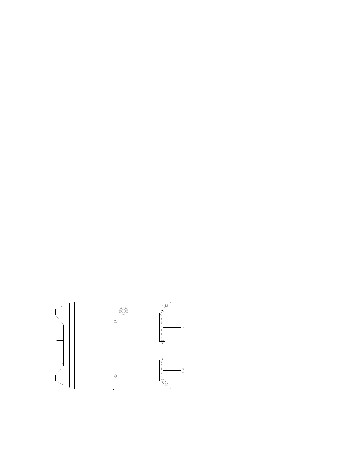
2.1 Connection Side of Print Mechanics
1 =
Pneumatic connection
2 =
Connecting cable SPI
(printhead + sensors)
3 =
Connecting cable Power
Figure 1

Machine Overview
Dynacode II Series
10
Operating Manual
08.16
2.2 Connector Assignment of Control Unit
N
A B C D E F G
M L K J HI
Figure 2
A =
Switch
B =
Serial interface RS-232
C =
USB Host interface (USB-B)
D =
Connecting cable Power
E =
Ethernet interface
F =
USB interface (USB-A)
G =
CF card slot
H =
Connection encoder
I =
Connecting cable SPI (printhead + sensor)
J =
Standard
Option
SUB-D female connector 15pin
External socket I/O-24
see chapter 6.1
SUB-D male connector 9pin
External input 5-8
see chapter 6.1
K =
Externer Ausgang 5-8 (Output II)
L =
Externer Eingang 1-4 (Input I)
M =
Externer Ausgang 1-4 (Output I)
N =
Power line
Dynacode II Series
Continuous Mode
08.16
Operating Manual
11
3 Continuous Mode
3.1 Material Speed
Please note that the material has sufficient adhesion at the pressure
transducer roll or encoder roll to permit the exact speed by the
encoder.
It is only possible to print when respecting the operating conditions,
i.e. the speed has to be observed.
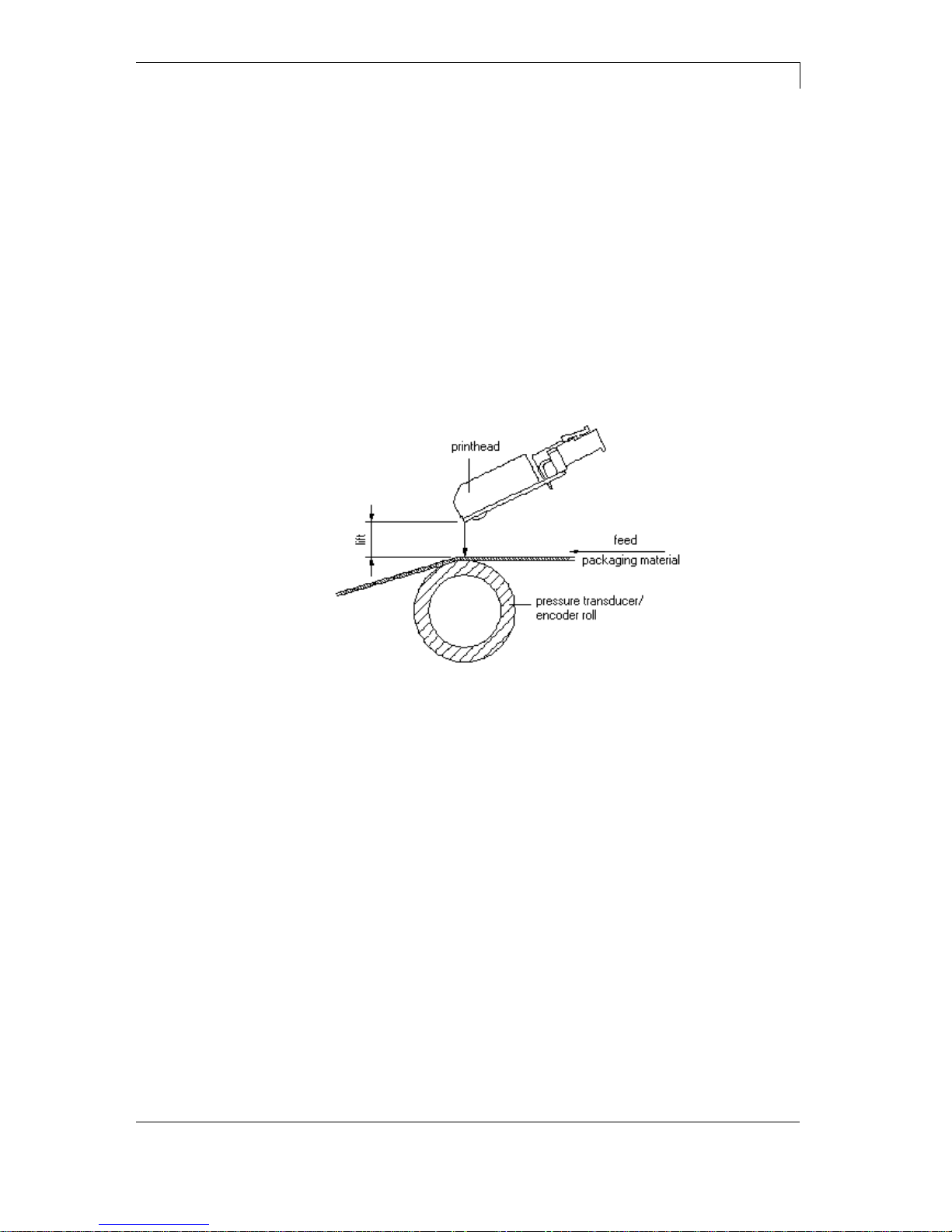
3.2 Print Principle
Figure 3
After starting a print order the printhead moves against the print
medium. The feed of material is registered by the encoder and then
evaluated. The printhead is in start position as long as the printing
onto the moving material is finished and then it moves back to its
home position.
Continuous Mode
Dynacode II Series
12
Operating Manual
08.16
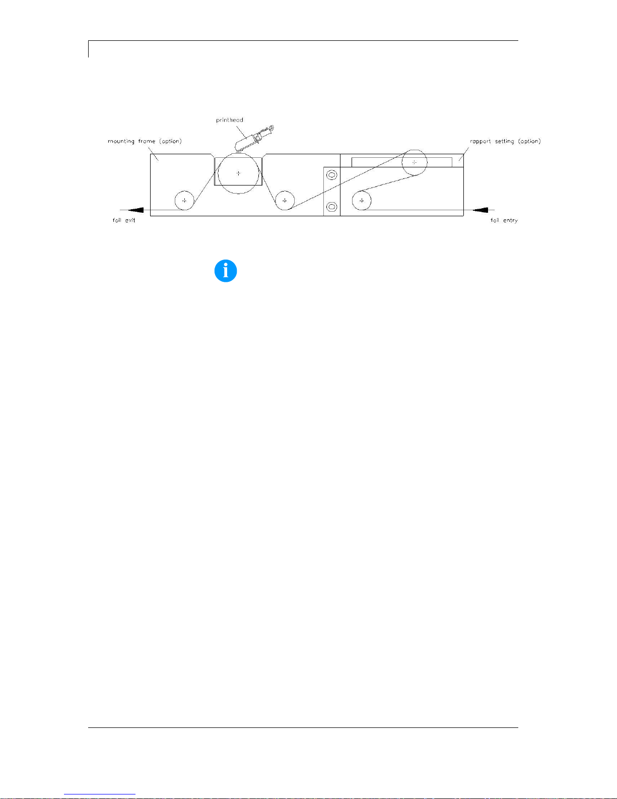
3.3 Material Guiding
Figure 4
NOTICE!
In case the encoder is connected to the counter-pressure roll or
the encoder roll you have to observe that the material has
sufficient adhesion at the pressure roll or encoder roll to guarantee
an exact speed by the encoder.
Dynacode II Series
Intermittent Mode
08.16
Operating Manual
13
4 Intermittent Mode
4.1 Print Principle
Figure 5
After starting a print order the printhead moves against the print
medium. Afterwards the printing carriage moves corresponding to the
set or transferred layout length linear over the material which is to be
printed. After the print procedure the printhead again lifts up and the
printing carriage moves again to the starting position.
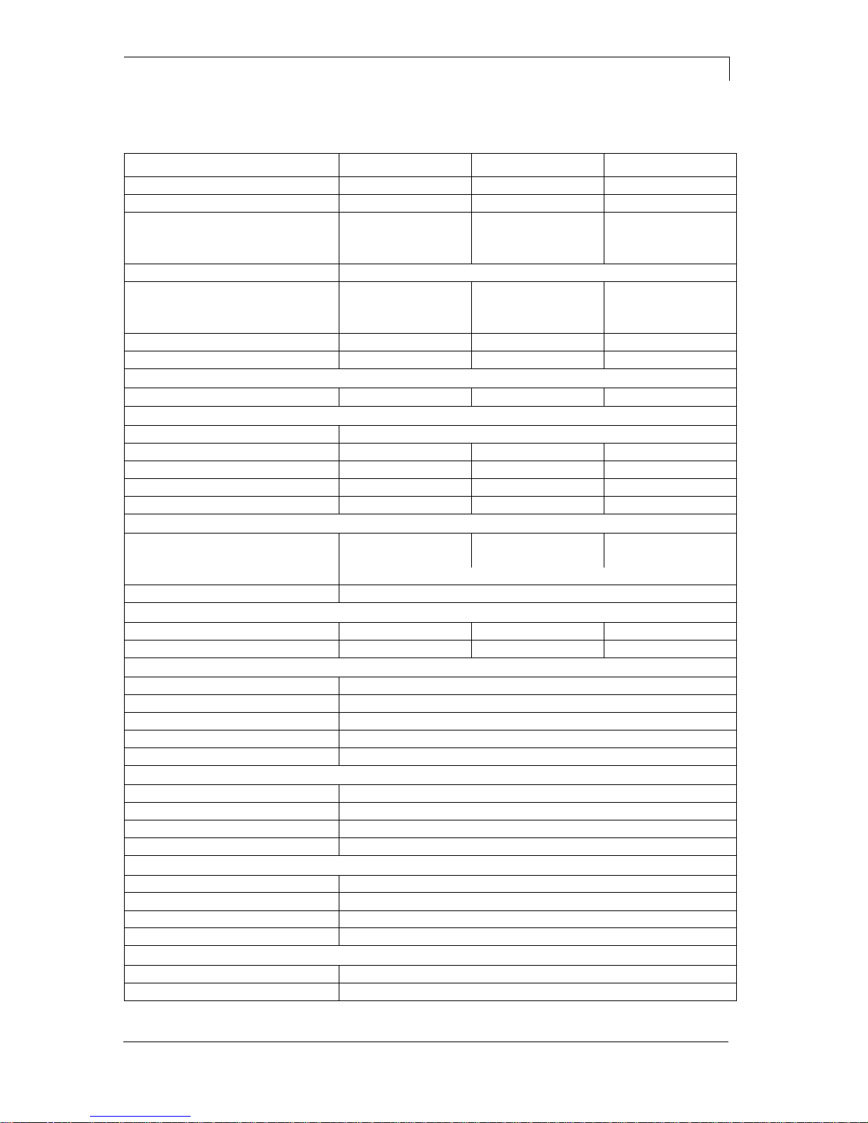
4.2 Print Position
NOTICE!
The direct print module is delivered with a default print length of
65 mm. In order to use the maximum print length of 75 mm, the print
position value must be changed to 93 (see chapter 9.5 Machine
Parameters (Intermittent Mode), page 54).
Figure 6
A: Print pos. / Start pos. value = 93
C: Max. position print end
B: Print pos. / Start pos. value = 83
D: Stand-by position


Dynacode II Series
Operating Conditions
08.16
Operating Manual
15
5 Operating Conditions
Before initial operation and during operation these operating
conditions have to be observed to guarantee save and interferencefree service of our direct print modules.
Therefore please carefully read these operating conditions.
Shipment and storage of our direct print modules are only allowed in
original packing.
Installation and initial operation of direct print modules is only allowed
if operating conditions were fulfilled.
Commissioning is prohibited until it can be established that, where
relevant, the machine into which the partly completed machinery is to
be incorporated complies with the provisions of Machinery Directive
2006/42/EC.
Initial operation, programming, operation, cleaning and service of our
direct print modules are only recommended after careful study of our
manuals.
Operation of direct print modules is only allowed by especially trained
persons.
NOTICE!
Perform trainings regularly.
Content of the training are chapter 5 (Operating Conditions),
chapter 8 (Loading the Transfer Ribbon Cassette) and chapter 11
(Maintenance and Cleaning).
These indications are also valid for someone else's equipment
supplied by us.
Only use original spare and exchange parts.
Please contact the manufacturer with respect to spare/wear parts.
The installation place of direct print module should be even, free of
vibration and currents of air are to be avoided.
The direct print modules have to be installed to ensure optimal
operation and servicing.
Conditions for
installation place

Operating Conditions
Dynacode II Series
16
Operating Manual
08.16
The installation of the power supply to connect our direct print
modules has to be effected according to the international rules and
regulations, especially the recommendations of one of the three
following commissions:
International Electronic Commission (IEC)
European Committee for Electro technical Standardisation
(CENELEC)
Verband Deutscher Elektrotechniker (VDE)
Our direct print modules are constructed according to VDE and have
to be connected to a grounded conductor. The power supply has to be
equipped with a grounded conductor to eliminate internal interfering
voltage.
Power line voltage and power line frequency: See type plate
Allowable tolerance of power line voltage:
+6% … −10% of nominal value
Allowable tolerance of power line frequency:
+2% … −2% of nominal value
Allowable distortion factor of power line voltage: <=5%
In case your net is infected (e.g. by using thyristor controlled
machines) anti-interference measures have to be taken. It is possible
to use one of the following possibilities:
Provide separate power supply to our direct print modules.
In case of problems please connect capacity-decoupled isolation
transformer or similar interference suppressor in front of our direct
print modules.
Emitted interference according to EN 61000-6-3: 01-2007
Interference voltage to wires according to EN 55022: 05-2008
Interference field power according to EN 55022: 05-2008
System perturbation according to EN 61000-3-2: 09-2005
Flicker according to EN 61000-3-3: 05-2002
Installation of
power supply
Technical data of
power supply
Anti-interference
measures
Stray radiation and
immunity from
disturbance

Dynacode II Series
Operating Conditions
08.16
Operating Manual
17
Immunity according to EN 61000-6-2: 03-2006
Stray radiation against discharge of static electricity according to
61000-4-2: 03-2009
Electromagnetic fields according to EN 61000-4-3: 05-2006,
ENV 50204: 03-1995
Fast transient burst according to EN 61000-4-4: 07-2005
Störfestigkeit gegen Stoßspannungen (Surge) gemäß EN 61000-
4-5: 11-2006
High-frequency tension according to EN 61000-4-6: 03-2009
Voltage interruption and voltage drop according to EN 61000-4-
11: 02-2005
EN 60950-1: 2006 - Safety of pachaging machines
EN 60204-1: 2006 - Safety of machinery - Electrical equipment of
machines - Part 1
All connecting lines have to be guided in shielded lines. Shielding has
to be connected on both sides to the corner shell.
It is not allowed to guide lines parallel to power lines. If a parallel
guiding cannot be avoided a distance of at least 0.5 m has to be
observed.
Temperature of lines between: −15 … +80 °C.
It is only allowed to connect devices which fulfil the request 'Safety
Extra Low Voltage' (SELV). These are generally devices which are
checked corresponding to EN 60950.
The data cables must be completely protected and provide with metal
or metallised connector housings. Shielded cables and connectors are
necessary, in order to avoid radiant emittance and receipt of electrical
disturbances.
Allowable lines
Shielded line:
4 x 2 x 0,14 mm² ( 4 x 2 x AWG 26)
6 x 2 x 0,14 mm² ( 6 x 2 x AWG 26)
12 x 2 x 0,14 mm² (12 x 2 x AWG 26)
Sending and receiving lines have to be twisted in pairs.
Maximum cable length:
interface V 24 (RS-232C) - 3 m (with shielding)
USB - 3 m
Ethernet - 100 m
Stray radiation and
immunity from
disturbance
Machine safety
Connecting lines to
external machines
Installation of
data lines

Operating Conditions
Dynacode II Series
18
Operating Manual
08.16
To avoid inadmissible heating, free air convection has to be ensured.
Protection according IP: 20
Ambient temperature °C (operation): Min. +5 Max. +40
Ambient temperature °C (transport, storage): Min. −25 Max. +60
Relative air humidity % (operation): Max. 80
Relative air humidity % (transport, storage): Max. 80
(bedewing of direct print modules not allowed)
We do not take any responsibility for damage caused by:
Ignoring our operating conditions and operating manual.
Incorrect electric installation of environment.
Building alterations of our direct print modules.
Incorrect programming and operation.
Not performed data protection.
Using of not original spare parts and accessories.
Natural wear and tear.
When (re)installing or programming our direct print modules please
control the new settings by test running and test printing. Herewith you
avoid faulty results, reports and evaluation.
Only specially trained staff is allowed to operate the direct print
modules.
Control the correct handling of our products and repeat training.
We do not guarantee that all features described in this manual exist in
all models. Caused by our efforts to continue further development and
improvement, technical data might change without notice.
By further developments or regulations of the country illustrations and
examples shown in the manual can be different from the delivered
model.
Please pay attention to the information about admissible print media
and the notes to the direct print module maintenance, in order to avoid
damages or premature wear.
We endeavoured to write this manual in an understandable form to
give and you as much as possible information. If you have any queries
or if you discover errors, please inform us to give us the possibility to
correct and improve our manual.
Air convection
Limit values
Guarantee
Dynacode II Series
Technical Data
08.16
Operating Manual
19
6 Technical Data
Dynacode II 53
Dynacode II 107
Dynacode II 128
Print width
53.3 mm
106.6 mm
128 mm
Resolution
300 dpi
300 dpi
300 dpi
Print speed
Continuous mode
50 … 800 mm/s
50 … 600 mm/s
50 … 450 mm/s
Intermittent mode
50 … 600 mm/s
50 … 600 mm/s
50 … 600 mm/s
Back speed
intermittend mode only: max. 600 mm/s
Print length
Continuous mode
6000 mm
3000 mm
3000 mm
Intermittent mode
75 mm
75 mm
75 mm
Frame passage width
customized
customized
customized
Printhead
Corner Type
Corner Type
Corner Type
Acoustic emission (measuring distance 1 m)
Average sound power level
60 dB(A)
65 dB(A)
68 dB(A)
Transfer ribbon
Ink
outside / inside (option)
Max. roll diameter
98 mm
82 mm
75 mm
Core diameter
25.4 mm / 1"
25.4 mm / 1"
25.4 mm / 1"
Max. length
900 m
600 m
450 m
Max. width
55 mm
110 mm
130 mm
Dimensions in mm (width x height x depth)
Print mechanics
w/o mounting frame
204 x 182 x 235
204 x 182 x 290
204 x 182 x 310
with mounting frame
depends on passage width
Control unit
251 x 96 x 207 - connecting cable set to mechanics 2.5 m
Weight
Print mechanics
9.5 kg
11 kg
11.7 kg
Electronics (incl. cable)
5.5 kg
5.5 kg
5.5 kg
Elektronik
Processor
High Speed 32 Bit
RAM
16 MB
Slot
Compact Flash card type I
Battery cache
for Real-Time clock (storage of data with shut-down)
Warning signal
acoustic signal when error
Interfaces
Serial
RS-232C (up to 115.200 Baud)
USB
2.0 High Speed Slave
Ethernet
10/100 Base T, LPD, RawIP-Printing, DHCP, HTTP, FTP
2 x USB Master
connection for external USB keyboard and memory stick
Connection values
Pneumatic connection
min. 6 bar dry and free of oil
Nominal voltage
110 … 230 V / 50 … 60 Hz
Nominal current
230 V / 1.5 A − 110 V / 3 A
Fuse values
2x T4A 250 V
Operation data
Temperature
5 … 40 °C
Humidity
max. 80% (non-condensing)
Technical Data
Dynacode II Series
20
Operating Manual
08.16
Dynacode II 53
Dynacode II 107
Dynacode II 128
Operation panel
Touchscreen Display
800 x 480 pixel with background lighting
screen size 7"
Operating functions
Home, function menu, maintenance, memory card, print start, test print,
feed, about menu
Settings
date, time, shift times
11 language settings (others on demand)
print and device parameters, interfaces, password protection
Monitoring
Stop printing if
end of ribbon / end of layout / printhead open
Status report
extensive status print with information about settings
e.g. print length counter, runtime counter,
photocell interface and network parameters
printout of all internal fonts and all supported bar codes
Fonts
Font types
6 Bitmap fonts, 8 Vector fonts/TrueType fonts, 6 proportional fonts
other fonts on demand
Character sets
Windows 1250 up to1257, DOS 437, 850, 852, 857
all West and East European Latin, Cyrillic, Greek
and Arabic (option) characters are supported
other character sets on demand
Bitmap fonts
size in width and height 0,8 … 5,6
zoom 2 … 9, orientation 0°, 90°, 180°, 270°
Vektor fonts/
TrueType fonts
size in width and height 1 … 99 mm
variable zoom
orientation 0°, 90°, 180°, 270°
Font attributes
depending on character font - bold, Italic, inverse, vertical
Font width
variable
Bar codes
1D bar codes
CODABAR, Code 128, Code 2/5 interleaved, Code 39, Code 39
extended, Code 93, EAN 13, EAN 8, EAN ADD ON, GS1-128,
Identcode, ITF 14, Leitcode, Pharmacode, PZN 7 Code, PZN 8 Code,
UPC-A, UPC-E
2D bar codes
Aztec Code, CODABLOCK F, DataMatrix, GS1 DataMatrix,
MAXICODE, PDF 417, QR Code
Composite bar codes
GS1 DataBar Expanded, GS1 DataBar Limited, GS1 DataBar
Omnidirectional, GS1 DataBar Stacked, GS1 DataBar Stacked
Omnidirectional, GS1 DataBar Truncated
all bar codes are variable in height, module width and ratio.
orientation 0°, 90 °, 180°, 270°.
Optionally with check digit and human readable line.
Software
Configuration
ConfigTool
Process control
NiceLabel
Design software
Labelstar Office Lite, Labelstar Office
Windows printer driver
Windows 7® 32/64 Bit, Windows 8® 32/64 Bit
Windows 8.1® 32/64 Bit, Windows 10® 32/64 Bit,
Windows Server 2008® (R2) 64 Bit
Windows Server 2012® 64 Bit, Windows Server 2012® (R2) 64 Bit
Technical details are subject to change.
Dynacode II Series
Technical Data
08.16
Operating Manual
21
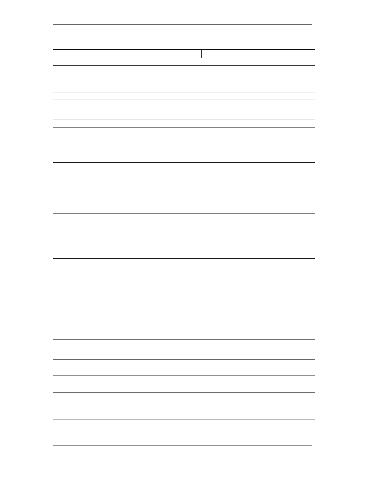
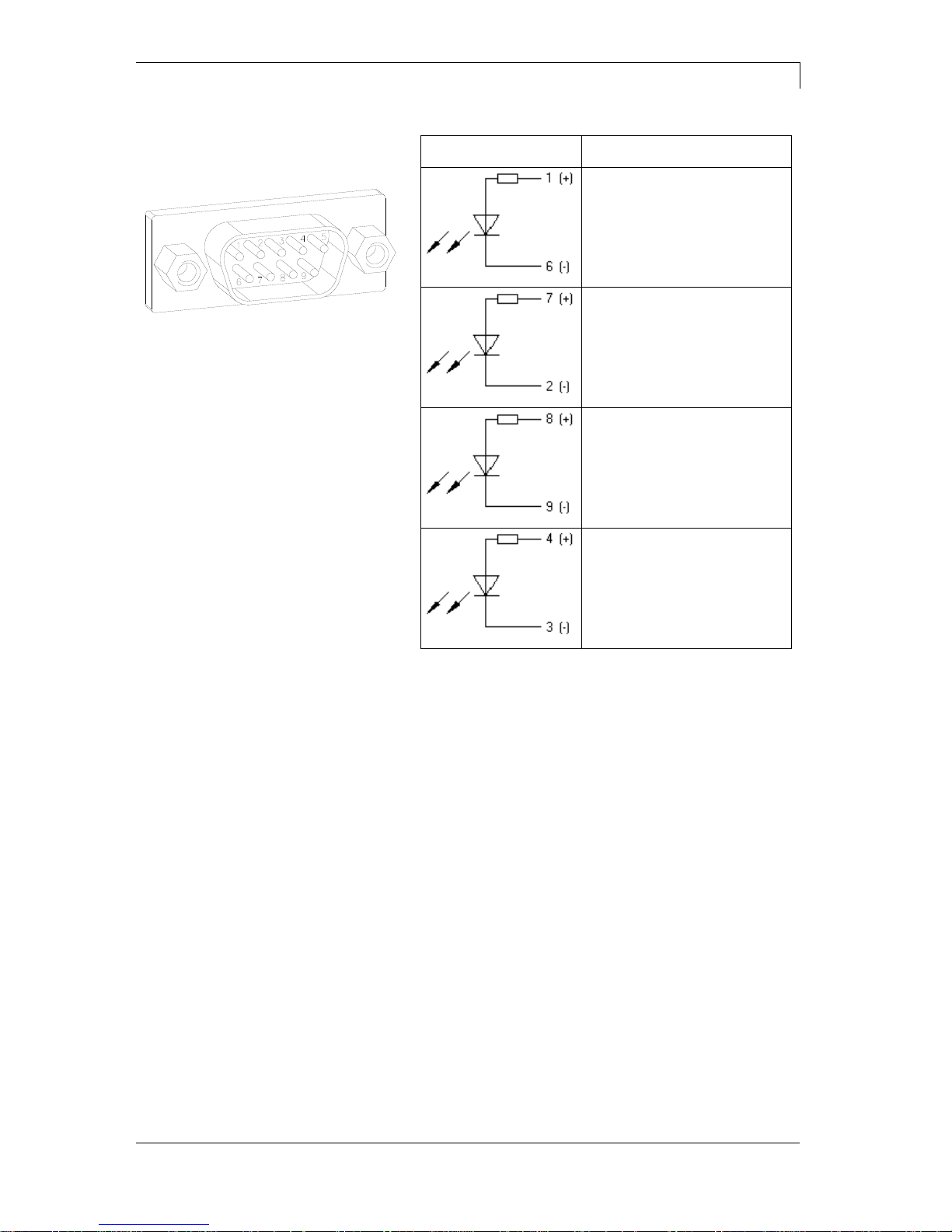
6.1 Control Inputs and Outputs (Standard)
Figure 7
A = Output 1
Port 9-12
B = Input 1
Port 1-4
C = Output 2
Port 13-16
D = External bushing
D = 15pin (I/O-24)
Port 1 + 9
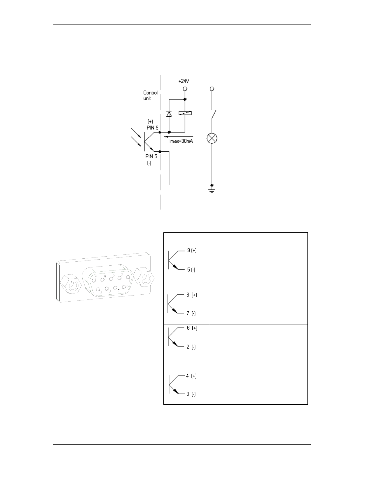
By means of the signal outputs different operating states of the print
module can be queried.
The signal outputs are provided by two 9-pin SUB-D-bushings
(OUTPUT I and OUTPUT II) on the back side of the control unit.
They consist of optocoupler semiconductor sections, which are
connected through and/or blocked according to different operating
states.
The maximum allowable current in a semiconductor section is
lmax = 30 mA.
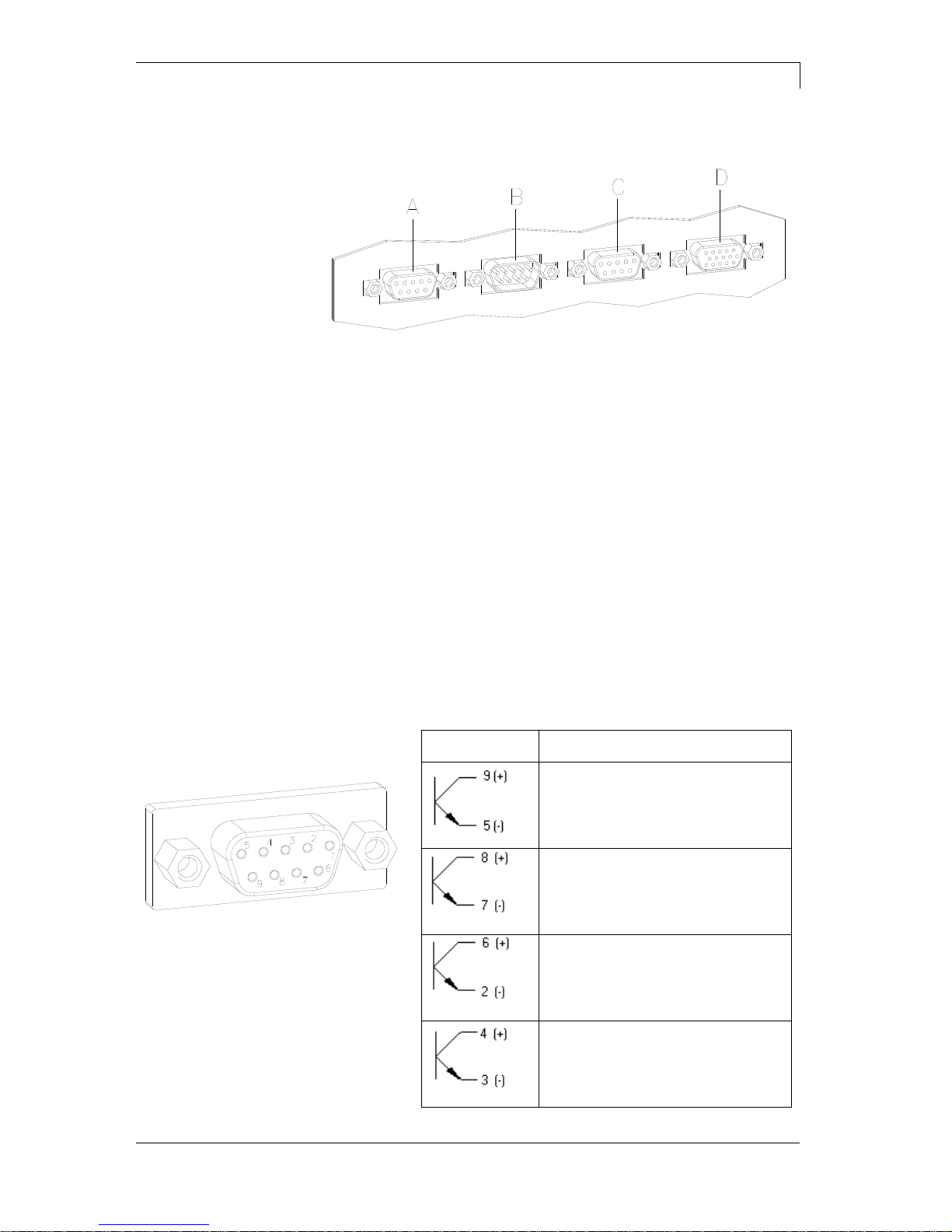
Output I
Figure 7, A
Figure 8
PIN (bushing)
Output I
Out 1 / Port 9: Error message
Each error status such as ribbon
error is displayed.
Out 2 / Port 10: Print order
The print module was activated by a
print order.
Out 3 / Port 11: Generation
The print module is filled with current
layout data.
Out 4 / Port 12: Layout print
The content of print memory is
transferred on the printable medium
by means of the printhead.
Plug connection - back
side of control unit
Control outputs
Technical Data
Dynacode II Series
22
Operating Manual
08.16
Connection of a lamp to a 24V relay by Out 1:
Figure 9
Output II
Figure 7, C
Figure 10
PIN (bushing)
Output II
Out 5 / Port 13: Print-Ready signal
It is indicated if the print module is
ready to process a start impulse. In
contrary to the print order signal, the
generating time is taken into
consideration.
Out 6 / Port 14: Printhead up
The printhead has reached the upper
rest position (e.g. return to zero
point).
Out 7 / Port 15: Return to start
After termination of print procedure
the flexible part of the print module is
moved back to the start position.
After the start position was reached a
new start can be released.
Out 8 / Port 16: Prior warning of
transfer ribbon end
Example

Dynacode II Series
Technical Data
08.16
Operating Manual
23
By means of the control inputs it is possible to control printing. The
control inputs at Input I are galvanic separated and have to be
provided with an external tension source. The signal level is active
"HIGH".
Input I
Figure 7, B
Figure 11
PIN (pin)
Input I
In 1 / Port 1: Print start
In 2 / Port 2: Not used
In 3 / Port 3: Reset external
counter
In 4 / Port 4: Not used
Connection of a switch with 24V voltage supply by In 1 / Port 1:
Figure 12
Control inputs
Example

Technical Data
Dynacode II Series
24
Operating Manual
08.16
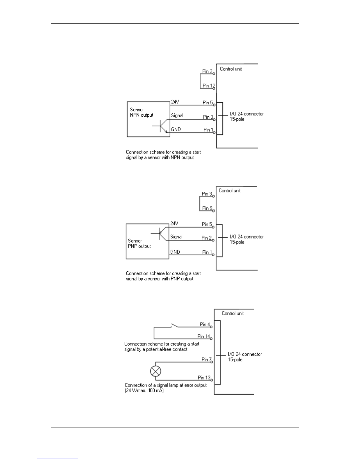
External bushing I/O-24
Figure 7, D
This input is executed as 15-pole and provides user-sided
24V/100mA.
In case of using this bushing, exists no galvanic
separation.
Figure 13
PIN
Port
Function
1, 6
Gnd
5,
10
24 V / 100 mA
3 1 Print start (NPN initiator)
2
Print start (PNP initiator)
4
Print start by
potentialfree contact
14
7
9
Signal lamp
24 V / 100
mA
(error)
13
PIN 1
white
PIN 2
brown
PIN 3
green
PIN 4
yellow
PIN 5
grey
PIN 6
pink
PIN 7
blue
PIN 8
red
PIN 9
black
PIN 10
purple
PIN 11
grey-pink
PIN 12
red-blue
PIN 13
white-green
PIN 14
brown-green
PIN 15
free
Pin assignment for
connecting cable
External bushing I/O-24
Dynacode II Series
Technical Data
08.16
Operating Manual
25
Figure 14
Figure 15
Figure 16
Example 1
Example 2
Example 3
Technical Data
Dynacode II Series
26
Operating Manual
08.16
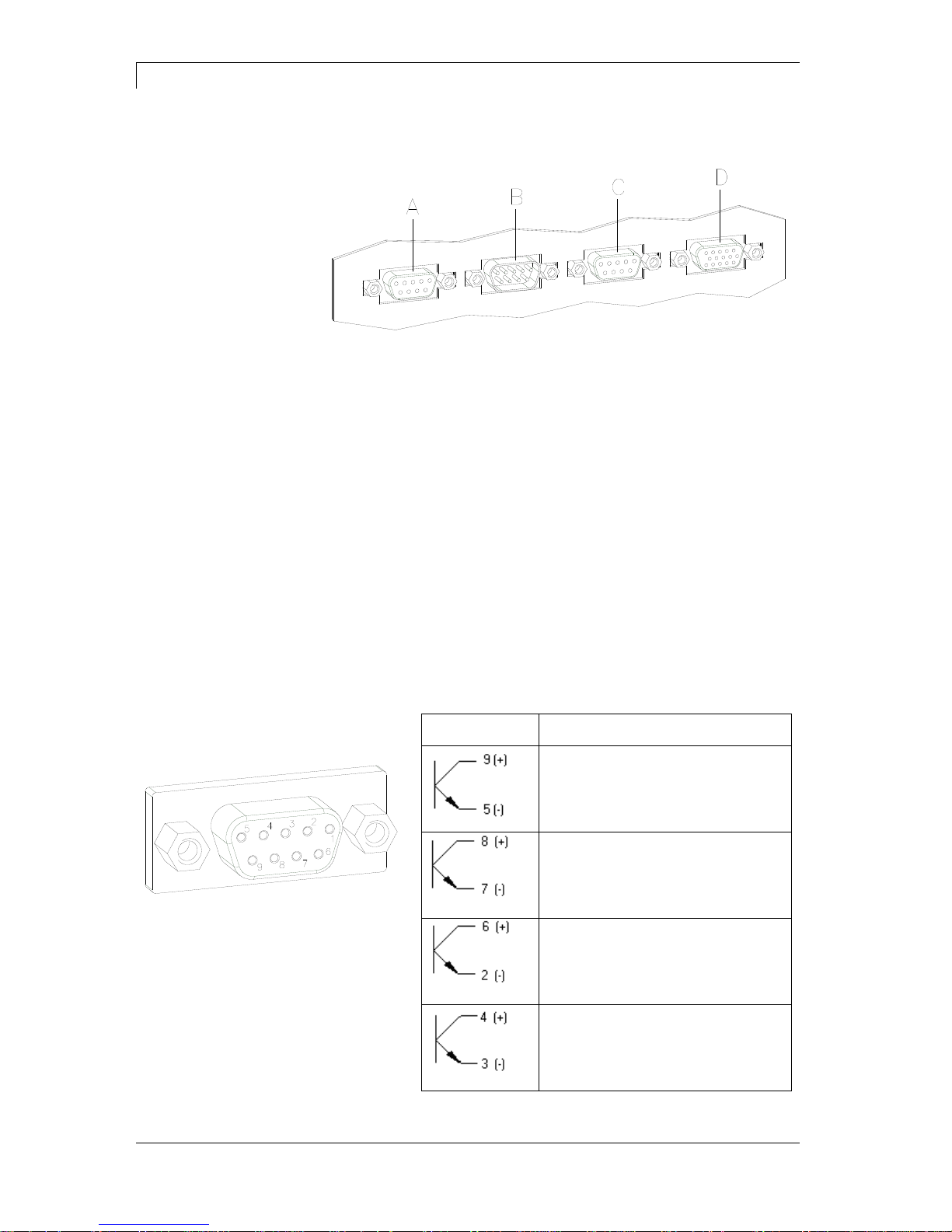
6.2 Control Inputs and Outputs (Option)
Figure 17
A = Output 1
Port 9-12
B = Input 1
Port 1-4
C = Output 2
Port 13-16
D = Input 2
Port 5-8
By means of the signal outputs different operating states of the print
module can be queried.
The signal outputs are provided by two 9-pin SUB-D-bushings
(OUTPUT I and OUTPUT II) on the back side of the control unit.
They consist of optocoupler semiconductor sections, which are
connected through and/or blocked according to different operating
states.
The maximum allowable current in a semiconductor section is
lmax = 30 mA.
Output I
Figure 7, A
Figure 18
PIN (bushing)
Output I
Out 1 / Port 9: Error message
Each error status such as ribbon
error is displayed.
Out 2 / Port 10: Print order
The print module was activated by a
print order.
Out 3 / Port 11: Generation
The print module is filled with current
layout data.
Out 4 / Port 12: Layout print
The content of print memory is
transferred on the printable medium
by means of the printhead.
Plug connection - back
side of control unit
Control outputs

Dynacode II Series
Technical Data
08.16
Operating Manual
27
Connection of a lamp to a 24V relay by Out 1:
Figure 19
Output II
Figure 7, C
Figure 20
PIN (bushing)
Output II
Out 5 / Port 13: Print-Ready signal
It is indicated if the print module is
ready to process a start impulse. In
contrary to the print order signal, the
generating time is taken into
consideration.
Out 6 / Port 14: Printhead up
The printhead has reached the upper
rest position (e.g. return to zero
point).
Out 7 / Port 15: Return to start
After termination of print procedure
the flexible part of the print module is
moved back to the start position.
After the start position was reached a
new start can be released.
Out 8 / Port 16: Prior warning of
transfer ribbon end
Example
Technical Data
Dynacode II Series
28
Operating Manual
08.16
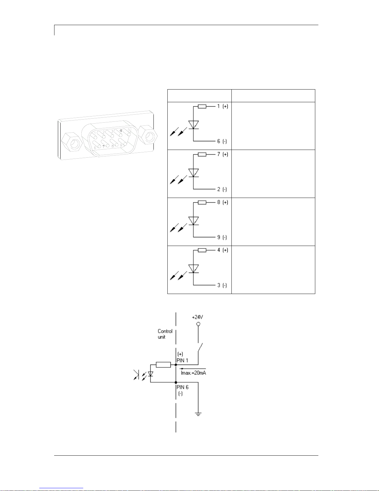
By means of the control inputs it is possible to control printing. The
control inputs at Input I are galvanic separated and have to be
provided with an external tension source. The signal level is active
"HIGH".
Input I
Figure 7, B
Figure 21
PIN (pin)
Input I
In 1 / Port 1: Print start
In 2 / Port 2: Not used
In 3 / Port 3: Reset external
counter
In 4 / Port 4: Not used
Connection of a switch with 24V voltage supply by In 1 / Port 1:
Figure 22
Control inputs
Example
Dynacode II Series
Technical Data
08.16
Operating Manual
29
Input II
Figure 17, D
Figure 23
PIN (pin)
Input II
In 5 / Port 5: Not used
In 6 / Port 6: Not used
In 7 / Port 7: Not used
In 8 / Port 8: Not used

Technical Data
Dynacode II Series
30
Operating Manual
08.16
6.3 Registered functions/profiles for inputs/outputs
Select menu I/O Parameters / I/O Profile to select the desired profile.
Port
Function
11 (Input)
Print start
12 (Input)
Error reset
13 (Input)
Counter reset
14 (Input)
No function
15 (Input)
Reset error
16 (Input)
No function
17 (Input)
No function
18 (Input)
No function
19 (Output)
Error
10 (Output)
Active print order
11 (Output)
Generation
12 (Output)
Printing
13 (Output)
Ready
14 (Output)
Error
15 (Output)
Return
16 (Output)
Transfer ribbon prior warning
Port
Function
11 (Input)
Print start
12 (Input)
Error reset
13 (Input)
Number of the file to load Bit 0 (Input)
14 (Input)
Number of the file to load Bit 1 (Input)
15 (Input)
Number of the file to load Bit 2 (Input)
16 (Input)
Number of the file to load Bit 3 (Input)
17 (Input)
Number of the file to load Bit 4 (Input)
18 (Input)
Number of the file to load Bit 5 (Input)
19 (Output)
error
10 (Output)
Active print order
11 (Output)
Generation
12 (Output)
Printing
13 (Output)
Ready
14 (Output)
Error
15 (Output)
Return
16 (Output)
Transfer ribbon prior warning
List of registered
functions for
Std_Direct
List of registered
functions for
StdFileSelDirect

Dynacode II Series
Technical Data
08.16
Operating Manual
31
Port
Function
11 (Input)
Print start
12 (Input)
Reset error
13 (Input)
Counter reset
14 (Input)
No function
15 (Input)
Error reset
16 (Input)
No function
17 (Input)
No function
18 (Input)
No function
19 (Output)
Ready
10 (Output)
No function
11 (Output)
No function
12 (Output)
No function
13 (Output)
Ready
14 (Output)
Error
15 (Output)
Return
16 (Output)
Transfer ribbon prior warning
Port
Function
11 (Input)
Print start
12 (Input)
Reset error
13 (Input)
Counter reset
14 (Input)
No function
15 (Input)
No function
16 (Input)
No function
17 (Input)
No function
18 (Input)
No function
19 (Output)
Error
10 (Output)
Active print order
11 (Output)
Generation
12 (Output)
Printing
13 (Output)
Print-Ready
14 (Output)
Printhead down
15 (Output)
Return
16 (Output)
Transfer ribbon prior warning
List of registered
functions for
SP_Direct0
List of registered
functions for
Old_Direct0

Technical Data
Dynacode II Series
32
Operating Manual
08.16
6.4 Pin Assignment of Encoder Socket
5-pin connecting bushing, contacts according to DIN 45322
Figure 24
PIN1 = 5 VDC
PIN2 = Encoder signal (channel A)
PIN3 = Encoder signal (channel B)
PIN4 = GND
Operating voltage:
5 VDC
Output signal:
TTL level
Resolution:
Can be set at the print module
Figure 25
only for continuous mode
Electrical data of
encoder
Connection of encoder

Dynacode II Series
Installation and Initial Operation
08.16
Operating Manual
33
7 Installation and Initial Operation
Lift the direct print module out of the box.
Check the direct print module for transport damages.
Set up the direct print module on a flat surface.
Remove foam transportation safeguards near the printhead.
Check delivery for completeness.
Print mechanics.
Control unit with cable.
Connecting cable.
Mini controller.
Manometer.
Pneumatic tube.
Push-on connector.
I/O accessories (mating connector for I/Os).
1 transfer ribbon roll.
Empty core, mounted on transfer ribbon rewinder.
Cleaning foil for printhead.
Documentation.
CD with printer drivers.
NOTICE!
Retain original packaging for subsequent transport.
Unpack the direct
print module
Scope of delivery

Installation and Initial Operation
Dynacode II Series
34
Operating Manual
08.16
7.1 Installation of Print Mechanics at Machines
NOTICE!
With the open printing unit (due to construction) the requirements
of EN60950-1 regarding fire protection casing are not fulfilled.
These must be ensured by the installation into the end device.
At the bottom of the mounting frame are two M8 threads that can be
used for the attachment at the machine. Additionally multi-functional
connecting parts are supplied.
Please observe the following conditions:
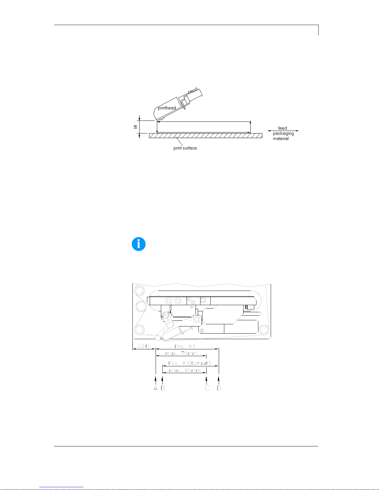
The maximum thread engagement of the M8 threads is 10 mm.
The print mechanics has to be installed with a distance from
printhead to brake stator of 1...2.5 mm (see illustration).
NOTICE!
A distance of 2 mm is recommended.
The best print results can be received if the silicon of the pressure
roll consists of a hardness of approx. 40° to 50 ° Shore A and/or
the elastometer of the counter-pressure plate shows a hardness
of approx. 60 ± 5 Shore A (average value of roughness Ra ≥ 3,2
mm).
The pressure roll/counter-pressure plate has to be installed
parallel to the linear movement of print unit and the focal line of
printhead. Discrepancies to the focal line and cavities in the print
surface can lead to an inferior print quality at these positions.
Figure 26
In case the machine is used without mounting frame, then it is
possible to fix the print module from the top with four M6 screws.
The maximum thread engagement of the M6 threads is 6 mm
(position of printhead see illustration).
Installation with
mounting frame
Installation without
mounting frame

Dynacode II Series
Installation and Initial Operation
08.16
Operating Manual
35
7.2 Required Space for Cable Outgoing
Figure 27
Figure 28
Standard:
Cable outgoing
sideways
Option:
Cable outgoing behind

Installation and Initial Operation
Dynacode II Series
36
Operating Manual
08.16
7.3 Connection of Pneumatic Power Supply
The pneumatic power supply for the printhead mechanics has to be
made available a minimum continuous pressure of 4 - 6 bars in front
of the pressure regulator. The maximum pressure in front of the
pressure regulator is 7 bars and 4 bars after the pressure regulator.
NOTICE!
A pneumatic power supply of 4 bars is recommended.
The compressed-air has to be dry and oil free.
The supplied pressure regulator with manometer is to connect with a
pneumatic tube Ø 8 mm via a plugging bolting to the pneumatic power
supply. It is necessary to make a connection between the pressure
regulator and the print mechanics via a pneumatic tube Ø 8 mm.
Please observe the following notes:
Position pressure regulator as near as possible to the print
mechanics.
The pressure regulator is only to operate in the direction that is
indicated on its underside. The direction shows the way of the
streaming air.
It is not allowed to bend the pneumatic tubes.
Shortening of the pneumatic tubes has to be made with a clean
right-angled cut without squashing the tube. If necessary use
special tools (available in pneumatic requirements).
Please observe a possible short length of the 8 mm pneumatic
tubes.
Druckmechanik
Druckluftversorgung
Pneumatikschlauch
min. 4 bar, max. 7 bar
Druckregler mit Manometer
Print mechanics
Pneumatic power supply
Pneumatic tube 8x1
Pressure regulator with manometer
Figure 29

Dynacode II Series
Installation and Initial Operation
08.16
Operating Manual
37
7.4 Adjustment of Pressure Power
Pressure power in dependence
of air pressure c53 / i53
(one pressure cylinder)
0
1
2
3
4
5
2 3 4 5
Air pressure in bar
Pressure in kg
Lift 1 mm Lift 2 mm Lift 3 mm
Pressure power in dependence
of air pressure c107 / i107
(two pressure cylinder)
0
1
2
3
4
5
6
7
8
2 3 4 5
Air pressure in bar
Pressure in kg
Lift 1 mm Lift 2 mm Lift 3 mm
Pressure power in dependence
of air pressure c128 / i128
(two pressure cylinders)
0
1
2
3
4
5
6
7
8
2 3 4 5
Air pressure in bar
Pressure in kg
Lift 1 mm Lift 2 mm Lift 3 mm
The pressure power of the printhead can be set with the pressure
regulator. The values are indicated in the following table:
NOTICE!
If the pressure power is set too low then the printhead has no
more contact to the counter-pressure plate. This damages the
printhead due to the missing heat dissipation during the
printout. In case of too low pressure an error message
appears. This error message is to protect the printhead for
overheating only and is not to use as print quality control (the
control suffers with too low pressure, too).
The Lift indicates the distance between printhead and counterpressure plate in idle mode of the device.
DC II 53
DC II 107
DC II 128
Recommended pressure power
40 N
40 N
40 N
Max. pressure power
45 N
45 N
45 N
As the mechanical wear and tear of the printhead increases with the
pressure power, the pressure power should be as low as possible.

Installation and Initial Operation
Dynacode II Series
38
Operating Manual
08.16
7.5 Connecting the Direct Print Module
The direct print module is equipped with a versatile power supply unit.
The device may be operated with a mains voltage of 110-230 V /
50-60 Hz without any adjustments or modifications.
CAUTION!
The direct print module can be damaged by undefined
switch-on currents.
Set de power switch to '0' before plugging in the direct
print module.
Insert plug of power cable into a grounded electrical outlet.
NOTICE!
Insufficient or missing grounding can cause faults during
operation.
Ensure that all computers and connection cables connected to
the direct print module are grounded.
Connect direct print module to computer or network with a
suitable cable.
7.6 Before Initial Operation
Mount print mechanics.
Connect all cables between print mechanics and control unit.
Protect cables against unintentional unscrewing.
Install compressed air connection.
Connect control unit and PC by direct print module interface.
Connect control unit and packaging machine by inputs and
outputs.
Connect power cable of control unit.
Connecting to the
power supply
Connecting to a
computer or to a
computer network

Dynacode II Series
Installation and Initial Operation
08.16
Operating Manual
39
7.7 Print Control
Because of the fact that the print module is always in control mode it
is only possible to transmit and not to start print orders by the
available interfaces (serial, parallel, USB or Ethernet). The print is
started by a start signal to the 'print start-control input'. It is necessary
for the control unit to recognise the moment of setting the start signal
and therefore it is possible and also necessary to observe the print
status by the outputs.
7.8 Initial Operation
Once all connections have been made:
Switch on the control unit.
Insert ribbon cassette (see chapter 8, page 41).
After loading the transfer ribbon cassette the measuring of
transfer ribbon begins and the printhead is moved to the print
position.


Dynacode II Series
Loading the Transfer Ribbon Cassette
08.16
Operating Manual
41
8 Loading the Transfer Ribbon Cassette
As for the electrostatic unloading the thin coating of the thermal
printhead or other electronic parts can be damaged, the transfer
ribbon should be antistatic.
The use of wrong materials can lead to direct print module
malfunctions and the guarantee can expire.
NOTICE!
Before a new transfer ribbon roll is loaded, the printhead must
be cleaned using printhead and roller cleaner (97.20.002). For
detailed information, please see page 82).
The handling instructions for the use of Isopropanol (IPA) must
be observed. In the case of skin or eye contact, immediately
wash off the fluid thoroughly with running water. If the irritation
persists, consult a doctor. Ensure good ventilation.
8.1 Transfer Ribbon With Coating Outside
Figure 30
Turn the lever (A) 90° in clockwise direction.
Remove the ribbon cassette from the print mechanics
by pulling handle (B).
Load a new ribbon roll as far as it will go onto the
unwinding roll (C).
Load an empty cardboard roll as far as it will go onto the
rewinding unit (D).
Insert the ribbon according to illustration.
Fix the ribbon with an adhesive tape at the empty roll
and tighten it by some turns of the core.
Push the ribbon cassette again onto print mechanics
and take care that the ribbon not rip.
Turn the lever (A) 90° anticlockwise.
NOTICE!
The above illustration shows a left hand printing system. If you
are using a right hand system, then the new roll is to be
inserted at the left and the cardboard core is to be inserted at
the right side.

Loading the Transfer Ribbon Cassette
Dynacode II Series
42
Operating Manual
08.16
8.2 Transfer Ribbon With Coating Inside
Figure 31
Turn the lever (A) 90° in clockwise direction.
Remove the ribbon cassette from the print mechanics
by pulling handle (B).
Load a new ribbon roll as far as it will go onto the
unwinding roll (C).
Load an empty cardboard roll as far as it will go onto
the rewinding unit (D).
Insert the ribbon according to illustration.
Fix the ribbon with an adhesive tape at the empty roll
and tighten it by some turns of the core.
Push the ribbon cassette again onto print mechanics
and take care that the ribbon not rip.
Turn the lever (A) 90° anticlockwise.
NOTICE!
The above illustration shows a left hand printing system. If you
are using a right hand system, then the new roll is to be
inserted at the left and the cardboard core is to be inserted at
the right side.

Dynacode II Series
Loading the Transfer Ribbon Cassette
08.16
Operating Manual
43
8.3 Increasing the Clamping Force for Ribbon Roll
NOTICE!
The use of high-quality transfer ribbon with a cardboard core is
recommended. A sample ribbon roll is included in the scope of
delivery. The clamping force of transfer ribbon roll placed on
the rewinding/unwinding unit is designed for this quality.
Figure 32
If other transfer ribbons are used, it can occur that the clamping force
of the spring plates (B) is not sufficient, in order to position the rolls
surely and to protect it against rotating.
When using transfer ribbons with plastic cores a safe positioning of
the roles cannot be ensured.
CAUTION!
Slippage of transfer ribbon roll placed on the rewinding/
unwind unit or the empty cardboard core leads to
malfunctions.
When using transfer ribbon rolls with plastic cores the
groove must be shimmed.
Remove screws (A) and spring plates (B).
Insert the shims (C, included in delivery) into the groove.
Fasten again spring plates (B) and shims (C) with screws (A).
Insert transfer ribbon roll and empty cardboard core on the
rewinding/unwinding unit.
Check firm position!
Increasing the
clamping force


Dynacode II Series
Function Menu
08.16
Operating Manual
45
9 Function Menu
9.1 Menu Structure (Continuous Mode)
Contrast
Transfer ribbon control
X Offset
Print Settings
Operating mode
Print offset
Print position
Layouts/cycle
Material speed control
Machine Parameters
Encoder resolution
Material feed
Material speed
Print length
Column printing
Material selection
Flip layout
Rotate layout
Alignment
Layout Settings
Operating mode
Ribbon Save
Speed
Transferband ribbon correction
Distance/Number of cycles
Expert parameters

Function Menu
Dynacode II Series
46
Operating Manual
08.16
Field handling
Codepage
External parameters
Language
Customized entry
Hotstart
Password protection
Print after measuring
Device Settings
Layout confirmation
Standard layout
IN signal level
OUT signal level
Debounce
Not ready: error
I/O profile
I/O Parameters
IP ddress
Net mask
Standard gateway
Geschwindigkeit/duplex
DHCP
Printer name
Network
MAC address
Port
Mode
Remote Console
Interval
COM1
Baud
Parity
Data bits
Stop bit
Interface
Start sign
Stop sign
Data memory
Port test

Dynacode II Series
Function Menu
08.16
Operating Manual
47
Protocol
Printhead resolution
Drive mapping
Emulation
Set date/time
Summertime
Start of summertime - Format
Start of summertime - Date
Start of summertime - Time
End of summertime - Format
End of summertime - Date
End of summertime - Time
Time shifting
Date/Time
Photocell parameters
Paper counter
Heater resistance
Printhead temperature
Transfer ribbon length
Transfer ribbon winding
Brake
Print examples
Service Functions
Encoder average
Output
Input
Online/Offline
Diagnostic counter
Warning diameter
Transfer ribbon prior warning
Load layout
Change directory
Load file
Save layout
Save configuration
Delete file
Formatting
CF Card / USB Stick

Function Menu
Dynacode II Series
48
Operating Manual
08.16
9.2 Menu Structure (Intermittent Mode)
Speed
Contrast
Transfer ribbon control
Print Settings
X Offset
Operating mode
Print offset
Print position
Layouts/cycle
Maschine Parameters
Back speed
Print length
Column printing
Material selection
Flip layout
Rotate layout
Alignment
Layout Settings
Operating mode
Ribbon Save
Transfer ribbon correction
Expert parameters
Field handling
Codepage
External parameters
Language
Customized entry
Hotstart
Password protection
Print after measuring
Device Settings
Layout confirmation
Standard layout

Dynacode II Series
Function Menu
08.16
Operating Manual
49
IN signal level
OUT signal level
Debounce
Not ready: error
I/O profile
I/O Parameters
Start signal delay
IP ddress
Net mask
Standard gateway
Geschwindigkeit/duplex
DHCP
Printer name
Network
MAC address
Port
Mode
Remote Console
Interval
COM1
Baud
Parity
Data bits
Stop bit
Interface
Start sign
Stop sign
Data memory
Port test
Protocol
Printhead resolution
Drive mapping
Emulation

Function Menu
Dynacode II Series
50
Operating Manual
08.16
Set date/time
Summertime
Start of summertime - Format
Start of summertime - Date
Start of summertime - Time
End of summertime - Format
End of summertime - Date
End of summertime - Time
Time shifting
Date/Time
Photocell parameters
Paper counter
Heater resistance
Printhead temperature
Transfer ribbon length
Transfer ribbon winding
Brake
Print examples
Service Functions
Encoder average
Output
Input
Online/Offline
Diagnostic counter
Warning diameter
Transfer ribbon prior warning
Load layout
Change directory
Load file
Save layout
Save configuration
Delete file
Formatting
CF Card / USB Stick

Dynacode II Series
Function Menu
08.16
Operating Manual
51
9.3 Print Settings
Indication of print speed in mm/s (see Technical Data, page 19). The
print speed can be determined for each print order anew.
The setting of print speed affects also the test prints.
Value range: 50 … 600 mm/s
Step size: 10 mm/s
Indication of value to set the print intensity when using different
materials, print speeds or printing contents.
Value range: 10% … 200 %.
Step size: 10%
Examination if the transfer ribbon roll is empty and/or if the ribbon was
torn at the unwinding roll.
Off: The ribbon control is deselected, i.e. the printer continues without
an error message.
On: The ribbon control is selected, i.e. the current print order is
interrupted and an Error Message appears at the printer display.
Strong sensibility: The printer reacts immediately to the end of the
transfer ribbon.
Weak sensibility: The printer reacts at approx. 1/3 more slowly to the
end of the transfer ribbon.
Displacement of the complete print transverse to the paper direction.
The displacement is possible only up to the edges of the printing zone
and is determined by the width of the focal line in printhead.
Value range: −90.0 … +90.0.
Speed
(intermittent
mode only)
Contrast
Ribbon control
X displacement

Function Menu
Dynacode II Series
52
Operating Manual
08.16
9.4 Machine Parameters (Continuous Mode)
It is not possible to start printing by the interface. The machine is
always in control mode and the print is released by the control input
Print Start. The operating mode is normally transferred with each
layout otherwise mode I/O dynamic continuous is used as standard
operating mode.
The following modes are available:
IO ST
IO static
The input signal is evaluated, i.e. it is printed as
long as the signal exists. The number of layouts,
which was entered at print start, is printed (level
evaluation of print start signal).
IO ST F
IO static continuous
Corresponds to IO static. Continuous means that
not only a defined number of pieces is processed
but the same layout is printed as long as new data
is transferred by interface.
IO DY
IO dynamic
The external signal is evaluated dynamically, i.e. in
case the direct print module is in 'waiting' mode a
single layout is printed at each signal changing
(flank evaluation of print start signal).
IO DY F
IO dynamic continuous
Corresponds to IO dynamic. Continuous means that
not only a defined number of pieces is processed
but the same layout is printed as long as new data
is transferred by interface.
Test mode
This operating mode corresponds to mode 2. After
the return of the print unit to the zero point of the
machine, however, internally a further cycle is
started (endurance test).
Direct start
A print order is transferred. After termination of
generating process the print order is executed
without an external signal.
Operating mode

Dynacode II Series
Function Menu
08.16
Operating Manual
53
Indication of distance of the layout (res. the first layout in case more
layouts per cycles are to be printed) to the zero point of machine.
Settings possible either in mm or ms.
Value range: 1 … 999 mm
Figure 33
Indication of position of print carriage in mm.
Value range: 12 … 93 mm
Indication of number of printed layouts per print start (cycle).
Value range: 1 … 25.
Figure 34
Check material speed at print start signal
Off (Default): Material speed is only checked if the set offset value is
taken into consideration. It is possible to activate print start signal
although the material is not yet in move. However, until the end the
material speed has to be inside the valid speed sector as otherwise
the print order is cancelled.
On: Material speed is checked at print start signal. Is the material
speed outside of the valid speed sector then the start signal is
ignored.
Print offset
Print position
Layouts/cycle
Check speed on start

Function Menu
Dynacode II Series
54
Operating Manual
08.16
Encoder resolution / material feed per encoder rotation
Indication of resolution of used encoder and material feed per rotation
of encoder in mm. These settings help measuring the material speed.
The material feeding per encoder rotation corresponds for instance, in
a 1:1 translation between the encoder and the roller, to the roller
circumference.
Indication of material speed (only for reading purposes).
9.5 Machine Parameters (Intermittent Mode)
No. of pieces
A print order with a defined number of pieces is
transferred. After the generating process the target
number and the actual number of pieces is shown in
the display. A cycle is started via signal input 1 or
with key . With each cycle the actual number
of pieces is increased by the number of printed
layouts. In case the target number of pieces is
reached the print order is finished and the display
shows again the main menu.
Continuous
A print order is transferred. After the generating
process the number of printed layouts is shown in
the display. A cycle is started via signal input 1 or
with key . With each cycle the number of
printed layouts is increased. The print order is active
as long as it is terminated by the user or in case of
new data transmission.
Test mode
This operating mode corresponds to mode 2. After
the return of the print unit to the zero point of the
machine, however, internally a further cycle is
started (endurance test).
Direct start
A print order is transferred. After termination of
generating process the print order is executed
without an external signal.
Indication of back speed of print mechanics after print end in mm/s.
Each cycle of the machine consists of printing and return to the zero
point of machine. It is possible to set the print speed and back speed
separately.
Because of this value you can select for low machine clock cycles an
operating method which saves the material and increases in this way
the life of the printhead.
Because of the mass moment of inertia it could be better to reduce the
speed at an installation position of the print unit at >30° horizontal.
Value range: 50 … 600 mm/s.
Resolution
Material speed
Mode
Back speed

Dynacode II Series
Function Menu
08.16
Operating Manual
55
Indication of distance of the layout (res. the first layout in case more
layouts per cycles are to be printed) to the zero point of machine.
Value range: 0 … 93 mm
Default: 0 mm
Figure 35
Indication of start position of print carriage in mm.
Value range: 0 … 93 mm
Default: 83 mm
Indication of the number of printed layouts per print start (cycle).
Value range: 1 … 25.
Figure 36
Print offset
Print position
Layouts/cycle

Function Menu
Dynacode II Series
56
Operating Manual
08.16
9.6 Layout
Indication of way the print mechanics has to move. The print length
depends on the length of the print mechanics.
Indication of width of one layout as well as how many layouts are
placed side by side on the backing paper.
With this print module, several columns can be printed, i.e. the
information of one column can be printed several times (depending on
its width) on a layout. Caused by this the use of the complete print
width is possible and the generating time is enormously reduced.
Selection of the used transfer ribbon material.
The axis of reflection is in the middle of the layout. If the layout width
was not transferred to the direct print module, automatically the
default layout width i.e. the width of the printhead is used. It is
recommended to use layouts with the same width as the printhead.
Otherwise this can cause problems in positioning.
According to standard the layout is printed ahead with a rotation of 0°.
If the function is activated, the layout is rotated by 180° and printed in
reading direction.
The adjustment of layout is effected only after Flip/Rotate layout, i.e.
the adjustment is independent of the functions Flip layout and Rotate
layout.
Left = The layout is aligned at the left-most position of printhead.
Centre
=
The layout is aligned at central point of printhead.
Right
=
The layout is aligned at right-most position of printhead.
Print length
Column printing
Material selection
Flip layout
Rotate layout
Alignment

Dynacode II Series
Function Menu
08.16
Operating Manual
57
9.7 Ribbon Save (Continuous Mode)
Off
No ribbon save.
Standard
Maximum ribbon save performance, i.e. with this
setting there is no loss of transfer ribbon (apart from
the safety distance of 1 mm, so the print fields are not
printed one into the other).
No settings are allowed with which the ribbon save no
more cannot be achieved. This particularly applies for
the print offset, which can only be adjusted now in the
valid range (see chapter 15.2, page 110).
Shift
Layout data can be printed several times laterally
displaced. A maximum utilization of transfer ribbon can
be achieved (see chapter 15.3, page 112).
SaveStrt
No start signal loss, direct print module regulates the
ribbon save quality automatically according to
requirement.
Automatic layout ribbon save and field ribbon save,
each without feedback (see chapter 15.4, page 115).
Determination of max. print speed.
On the base of this value all necessary calculations e.g. feedback
distance and smallest possible print offset are being calculated.
Example
Speed = 400
Mode = Standard
Very good ribbon save result between
50 mm/s and 400 mm/s.
However, if you print with a speed higher than 400 mm/s, then the
ribbon save result is decreased and/or the ribbon save can no longer
be executed, because the back-feed way was designed to 400 mm/s.
Please consider: if speed is set to 400 and only 300 mm/s are printed,
then a smaller number of cycles is reached as if speed is set to 300,
however a reserve of 100 mm/s is still available.
Therefore the speed value should be always set to the maximum print
speed. If the number of cycles is not sufficient, the rewind correction
should be applied.
Mode
Speed

Function Menu
Dynacode II Series
58
Operating Manual
08.16
9.8 Ribbon Save (Intermittent Mode)
Off
No ribbon saving.
Standard
Maximum ribbon save performance, i.e. with this
setting there is no loss of transfer ribbon (apart from
the safety distance of 1 mm, so the print fields are not
printed one into the other).
No settings are allowed with which the ribbon save no
more cannot be achieved. This particularly applies for
the print offset, which can only be adjusted now in the
valid range (see chapter 15.5, page 115).
Shift
Layout data can be printed several times laterally
displaced. A maximum utilisation of transfer ribbon can
be achieved (see chapter 15.6, page 116).
9.9 Device Settings
Off: The complete print memory is deleted.
Keep graphic: A graphic res. a TrueType font is transferred to the
direct print module once and stored in the direct print module internal
memory. For the following print order only the modified data is
transferred to the direct print module. The advantage is the saving of
transmitting time for the graphic data.
The graphic data created by the direct print module itself (internal
fonts, bar codes, ...) is generated only if they were changed. The
generating time is saved.
Delete graphic: The graphics res. TrueType fonts stored in the
internal memory is deleted but the other fields are kept.
Indication of the font used in the direct print module.
The following possibilities are available:
Codepage 1252 West European (former ANSI)
Codepage 437 English
Codepage 850 Western European
Codepage 852 Slavic
Codepage 857 Turkish
Codepage 1250 Central and East European
Codepage 1251 Cyrillic
Codepage 1253 Greek
Codepage 1254 Turkish
Codepage 1257 Baltic
WGL4
Please find the tables referring to the above mentioned character sets
on www.carl-valentin.de/Downloads.
Mode
Field handling
Codepage

Dynacode II Series
Function Menu
08.16
Operating Manual
59
Layout dimension only: The parameters for layout length, gap
length and layout width can be transferred to the printing system. All
other parameter settings are to be made directly at the printing
system.
On: Sending parameters such as speed and contrast via our design
software to the printing system. Parameters which are set directly at
the printing system before are no longer considered.
Off: Only settings made directly at the printing system are considered.
Selection of language the display indicates texts in the graphic
display.
At the moment the following languages are available: German,
English, French, Spanish, Portuguese, Dutch, Italian, Danish, Finnish,
Polish, Czech, Hungarian, Russian, Chinese (option), Ukrainian.
On: The question referring the customized variable appears once
before the print start at the display.
Auto: The question referring the customized variable appears after
every printed layout.
Off: No question appears at the display. In this case the stored default
value is printed.
On: Continue an interrupted print order after switching on the printer
anew
Off: No question appears at the display. In this case the stored default
value is printed 14.1, page 105).
By a password several functions can be blocked, so the user cannot
work with them. There are several applications in which the use of
password protection makes sense (see chapter 14.2, page 107).
On: A new print order is only printed after confirmation at the device.
An already active continuing print order is printed as long as the
confirmation is effected at the device.
Off: No query appears at the display of control unit.
Print after measuring
On: If an error occurred during printing, whose removal can be
recognized by the module (e.g. transfer ribbon end, cassette open),
then the module changes after the error correction (e.g. cassette
closed again) immediately in the 'ready' mode.
Off: After removal and confirmation of error, the module changes into
'stopped' mode.
On: If a print order is started without previous definition of layout, the
standard layout is printed.
Off: If a print order is started without previous definition of layout, an
error message appears in the display.
External parameters
Language
Customized entry
Hotstart
Password protection
Layout confirmation
D/Me
Standard layout

Function Menu
Dynacode II Series
60
Operating Manual
08.16
9.10 I/O Parameters
Indication of signal at which a print order is started
+ = active signal level is 'high' (1)
- = active signal level is 'low' (0)
x = signal level is not activated
s status can be affected by interface *
The modification of the signal level is only taken into consideration for
the operating modes I/O static, I/O dynamic, I/O static continuous and
I/O dynamic continuous.
Angabe des Signalpegels für Ausgabesignal.
+ = active signal level is 'high' (1)
- = active signal level is 'low' (0)
s = status can be affected by interface *
Indication of debounce time of the dispenser input. The setting range
of the debounce time is between 0 and 100 ms.
In case the start signal is not clear then you can debounce the input
by means of this menu item.
Indication in time per second of the delay for the start signal.
Value range: 0.00 … 9.99.
On: If a print order is active but the direct print module is not ready to
process the order (e.g. if it is already in 'printing' mode), then an error
message appears.
Off: No error message appears.
Selection of the available configurations Std_Direct (factory setting),
StdFileSelDirect, SP_Direct0 or Old_Direct0.
The corresponding assignment is indicated in chapter 6.3, page 30.
9.11 Network
For more information, please see the separate manual.
*
in combination with Netstar PLUS
IN signal level
OUT signal level
Debounce
Start signal delay
(intermittent mode)
Not ready: error
I/O Profile

Dynacode II Series
Function Menu
08.16
Operating Manual
61
9.12 Remote Console
For more information please contact our sales department.
9.13 Interface
COM1:
0 - serial interface Off.
1 - serial interface On.
2 - serial Interface On, no error message occurs in case of a
transmission error.
Baud:
Indication of bits which are transferred per second (speed of data
transfer).
Value range: 1200, 2400, 4800, 9600, 19200, 38400, 57600 and
115200.
P = Parity:
N - No parity
E - Even
O - Odd
Please observe that the settings correspond to those of the direct print
module.
D = Data bits:
Setting of data bits.
Value range: 7 or 8 Bits.
S = Stop bits:
Indication of stop bits between bytes.
Value range: 1 or 2 stop bits.
SOH: Start of data transfer block Hex format 01
ETB: End of data transfer block Hex formal 17
Two different start / en signs can be set. The settings are normally
SOH = 01 HEX and ETB = 17 HEX. Several host computers cannot
process these signs and therefore SOH = 5E HEX and ETB = 5F
cannot be set.
Standard: After starting a print order the direct print module buffer
receives data as long as it is filled.
Advanced: During a current print order data is received and
processed.
Off: After starting a print order no more data is received.
Check whether the data are transferred via the interface.
COM1 / Baud /
P / D / S
Start sign / End sign
Data memory
Porttest

Function Menu
Dynacode II Series
62
Operating Manual
08.16
9.14 Emulation
CVPL: Carl Valentin Programming Language
ZPL: Zebra® Programming Language
Change between CVPL protocol and ZPL II® protocol.
The direct print module performs a restart and ZPL II® commands are
transformed into CVPL commands internally by the direct print module
and then executed by the direct print module.
At activated ZPL II® emulation the printhead resolution of the emulated
direct print module must be set, e.g. 11.8 Dot/mm (= 300 dpi).
NOTICE!
If the printhead resolution of the Zebra® printer differs from that
of the Valentin device, then the size of objects (e.g. texts,
graphics) complies not exactly.
The access to Zebra® drives
B: CF card
R: RAM Disk (standard drive, if not indicated)
is rerouted to the corresponding Valentin drives
A: CF
R: RAM Disk
This can be necessary if the available space on the RAM disk (at
present. 512 KByte) is not sufficient or if bitmap fonts are downloaded
to the direct print module and be stored permanently.
NOTICE!
As the printer build-in fonts in Zebra® printers are not available
in Valentin devices, this can cause small differences in the text
image.
Protocol
Printhead resolution
Drive mapping

Dynacode II Series
Function Menu
08.16
Operating Manual
63
9.15 Date & Time
The upper line of display shows the current date, the second line the
current time.
On: Module automatically adjust clock for daylight saving changes.
Off: Summertime is not automatically recognized and adjusted.
Select the format in which you want to define beginning summertime.
The above example indicates the default setting (European format).
DD
Day
WW
Week
WD
Weekday
MM
Month
YY
Year
next day
only next day is taken into consideration
By means of this function you can enter the date at which summertime
has to start. This entry refers to the previously selected format.
Example: summertime is automatically adjusted at last Sunday in
March (03).
By means of this function you can define the time when you want to
start summertime.
Select the format in which you want to define end of summertime. The
example above indicates the default setting (European format).
By means of this function you can define the date when you want to
stop summertime. The entry refers to the previously selected format.
Example: summertime is automatically adjusted at last Sunday in
October (10).
By means of this function you can define the time when you want to
stop summertime.
By means of this function you can enter time shifting in hours and
minutes (for automatically adjustment from summer and wintertime).
This entry refers to the direct print module time set currently.
Setting of
date and time
Summertime
Start of summertime –
Format
Start of summertime –
Date
Start of summertime –
Time
End of summertime –
Format
End of summertime –
Date
End of summertime –
Time
Time shifting

Function Menu
Dynacode II Series
64
Operating Manual
08.16
9.16 Service Functions
NOTICE!
So that the distributor res. the direct print module manufacturer
in case of service can offer fast support all necessary
information such as selected parameters can be taken directly
from the device.
H = Cover switch
Only available at devices with cover switch.
0 = oper cover
1 = closed cover
P = Pressure
Indication of value 0 or 1 or compressed air control.
R1 = Transfer ribbon rewinding roll
Indication of transfer ribbon rewinding roll status.
4 states are indicated (no marking in photocell, marking from
right, marking from left, marking completely in photocell).
R2 = Transfer ribbon unwinding roll
Indication of transfer ribbon unwinding roll status.
4 states are indicated (no marking in photocell, marking from
right, marking from left, marking completely in photocell).
C = Carriage
Indication of print carriage position.
ENC
=
Encocer
Indication of current state of encoder
D: Indication of printhead attainment in meters.
G: Indication of direct print module attainment in meters.
To achieve a high print quality, the indicated Ohm value must be set
after an exchange of printhead.
Indication of printhead temperature. The printhead temperature
corresponds normally to the room temperature. In case the maximum
printhead temperature is exceeded, the current print order is
interrupted and an error message appears at the direct print module
display.
Selection of the used transfer ribbon length (300 m, 450 m, 600 m,
900 m or 1000 m). With smaller ribbons, a higher number of cycles
can be reached.
Selection of the coating side of transfer ribbon, either outside or
inside.
Default: Coating outside
Photocell parameters
Laufleistung
Heater resistance
Printhead temperature
Ribbon
Ink side

Dynacode II Series
Function Menu
08.16
Operating Manual
65
Adjustment of brake power for acceleration and braking in %.
Adjustment of brake power during printing.
Settings
=
Printout of all settings such as speed, and transfer
ribbon material.
Bar codes
=
Printout of all available bar code types.
Fonts
=
Printout of all available font types.
Indication of level for inputs of the IO parameters.
0 = Low
1 = High
Indication of the level for outputs of the IO parameters.
0 = Low
1 = High
The encoder values with print start in logging files are registered on
CF card. By means of this data, a graphic chart of the encoder curve
can be created.
For further information please contact our support department.
DiaRW = Diameter of transfer ribbon rewinding roll.
DiaRU = Diameter of transfer ribbon unwinding roll.
Number of values by which the encoder signals is averaged. The
more higher the value the more slowly react the device to speed
modifications.
Relevant results are counted and registered in RAM memory. The
protocole get lost after switching off the device.
RInt = Real Interrupts
The start input impulses are counted directly at the Interrupt.
Dbnc = Debounced
The start input impulses that are longer than the set debounce time
are counted. Only these start impulses can lead to a print. If a start
impulse is too short, no print is released. This is recognized by the fact
that RInt is counted, Dbnc not.
NPrn = Not Printed
The debounced start input impulses that have not lead to a print are
counted. Causes: no active print order, print order stopped (manually
or because of an error) or the printing system ist still active with the
processing of a print order.
PrtStrtReset = The counters are reset.
PrtStrtTime = Measured length of the last start impulse in ms.
Brake Power
Brake Power P
Print examples
Input
Output
Diagnostic:
Encoder Profiling
Diameters of transfer
ribbon rolls
Encoder average
I/O Status

Function Menu
Dynacode II Series
66
Operating Manual
08.16
This function is activated e.g. if the transfer ribbon is to be changed. It
is avoided that a print order is processed although the module is not
ready. The respective state is indicated in the display.
Standard: Off
Online: Data can be received by interface. The keys of the touchscreen are only active, if you changed in the Offline mode.
Offline: The keys of the touch-screen are still active but received data
are not processed. If the module is again in Online mode then new
print orders can be again received.
Before the end of transfer ribbon, a signal is send by the control
output.
Setting of transfer ribbon advance warning diameter.
In case you enter a value in mm then a signal appears via control
output when reaching this diameter (measured at transfer ribbon roll).
9.17 Main Menu
Switch on the direct print module and the display shows the Home
screen
Press button to display information such as module type, current
date and time, version number of firmware and used FPGA.
Online / Offline
Transfer ribbon
advance warning
Warning diameter

Dynacode II Series
Touch-Screen Display
08.16
Operating Manual
67
10 Touch-Screen Display
10.1 Touch-Screen Display Structure
The touch-screen display shows an intuitive graphic user interface
with well-defined symbols and buttons.
The touch-screen display informs about the current device status and
status of the print order, alerts in case of an error and indicates the
device settings in the menu.
The desired settings are made by selecting the buttons on the touchscreen display.
Figure 37
11
Home screen
12
Selection of parameter settings
13
Setting of maintenance parameters
14
Memory card menu access
15
Indication of device information
16
Starting layout feed
17
Starting test print
18
Starting print job
19
Name of currently selected layout
Number of printed layouts / total amount
10
Transfer ribbon status
11
Device name (indicated in network)
12
Current date and time
1 2 3 4
8 7 6 5
12
11
10
19

Touch-Screen Display
Dynacode II Series
68
Operating Manual
08.16
10.2 Different Menus
Figure 38
The selected (active) menu is highlighted on orange background.
If a selected menu contains so-called submenus, these are blue
highlighted.
Different parameters are combined in a submenu.
Figure 39
The left display side shows the available submenus. The currently
selected (active) submenu is highlighted on orange background.
Press to return one level.
Press to change to the start screen at any time.
Indication of main
menus
Indication of submenus

Dynacode II Series
Touch-Screen Display
08.16
Operating Manual
69
10.3 Favorites List
Figure 40
Press Functions to display the a Favorites zone in the first place.
The user can store the most important parameters for his application
to have a fast as possible access.
Figure 41
Press long (2 s) on a parameter (e.g. print speed) to display the
appropriate selection.
Add parameters to
favorites

Touch-Screen Display
Dynacode II Series
70
Operating Manual
08.16
Press Add to favorites to add the selected parameter to the favorites
list.
Figure 42
Figure 43
Press long (2 s) on a parameter (e.g. print speed) to display the
appropriate selection. Press Remove from favorites to remove the
selected parameter from the favorites list.
Remove parameters
from favorites

Dynacode II Series
Touch-Screen Display
08.16
Operating Manual
71
10.4 Parameter Input
Figure 44
Figure 45
In the header of input dialog the name of the parameter and the
permissible value range are shown. The input is checked for validity. If
the entered value not permissible, the button is blocked.
Parameter input
Numeric input
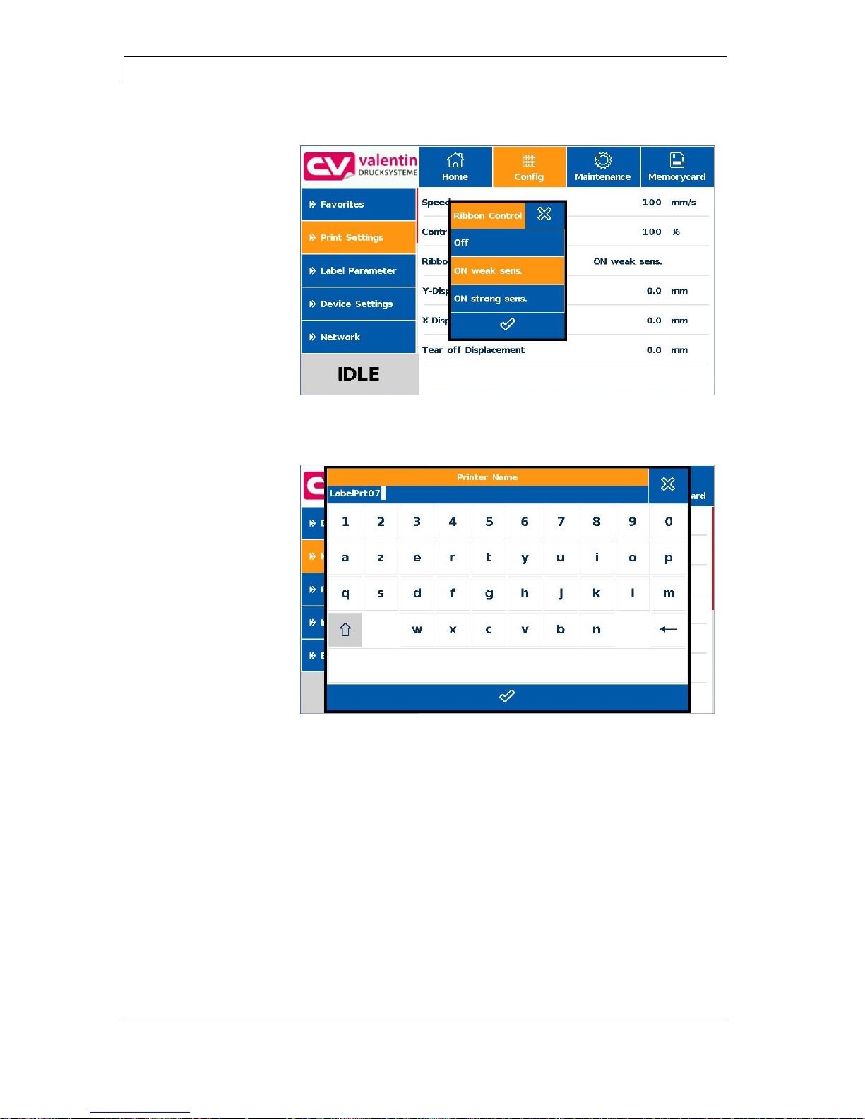
Touch-Screen Display
Dynacode II Series
72
Operating Manual
08.16
Figure 46
Figure 47
Selection from list
Alphanumeric input

Dynacode II Series
Touch-Screen Display
08.16
Operating Manual
73
10.5 Navigation Zones
Figure 48
The respective navigation zone can be moved with an appropriate
swipe movement from top to bottom or from the bottom up.
NOTE!
With the used resistive touch screen variant a certain pressure
on the display is needed.
It is not possible to navigate on the display with the swipe
movement to the left and right with a finger (well-known from
smartphones).
The position indications signalise the detail of the total list currently
visible. If no position indication is visible then the total list can be
displayed on the display. A swipe movement from top to bottom
and/or from the bottom up is not possible.
Position
indication
Position
indication
Navigation Navigation
zone 1 zone 2

Touch-Screen Display
Dynacode II Series
74
Operating Manual
08.16
10.6 Maintenance Zone
Different settings for the display indication can be done.
Figure 49
Print preview activated On/Off
With activated print preview a picture of the currently printed layout is
shown on the display. If the function is not activated, the field remains
empty.
Figure 50
Maintenance - Print
preview

Dynacode II Series
Touch-Screen Display
08.16
Operating Manual
75
Zoom
Selection of a certain zoom value for the representation of print
preview.
Figure 51
Label: The complete layout is fit to the indication zone.
Fields: Only the print range is fit to the indication zone.
User: A freely defined zone is fit to the indication zone
User: (see Labelstar Office).
1 .. 8: Manual zoom factor to scale the complete layout down.
Preview Interval
During a running print order the preview is refreshed in the set
interval.
Figure 52
Value range: 0 .. 10 seconds

Touch-Screen Display
Dynacode II Series
76
Operating Manual
08.16
Figure 53
Calibration:
The touch screen display is calibrated, i.e. the position of printhead is
adjusted.
Figure 54
For the start of calibration the display must be touched at any position.
Afterwards three red points are shown successively and you have to
touch them as exact as possible. The calibration is finished with it.
Background light:
Setting of contrast of background lighting.
Value range: 0 .. 100%.
Maintenance - LCD

Dynacode II Series
Touch-Screen Display
08.16
Operating Manual
77
Figure 55
Different system settings such as set printer type, reset paper counter
etc. can be made.
However, for the settings the corresponding password is necessary.
Figure 56
Maintenance - System
settings

Touch-Screen Display
Dynacode II Series
78
Operating Manual
08.16
10.7 Memory Menu
Figure 57
1
Contents of current directory
2
Loading of selected layout and starting the print job
3
Preview zone
If available, a preview of the selected layout is displayed
4
Changing to the file manager (Explorer)
Compact Flash Card
USB Stick
1 2 3 4

Dynacode II Series
Touch-Screen Display
08.16
Operating Manual
79
Figure 58
1
Change the number of copies
2
Value of defined variable
3
Customer query
4
Quick start of printout
5
List of variables defined on the layout
Figure 59
Enter the number of layouts to be printed.
Input of variables
Number of copies
3 2
5 4 1

Touch-Screen Display
Dynacode II Series
80
Operating Manual
08.16
10.8 Information Zone
Figure 60
By pressing the Info button the versions of the installed components
are displayed.
10.9 Change to Foil Keyboard
Press long (> 3 s) on the company logo left above, and the display
changes to the indication of a conventionalize foil keyboard. The
settings can be done by the standard operating panel (see page 45).
Press to change to the previous view.
Figure 61
For more information about the use of printer and its foil keyboard can
be found in chapter 9.

Dynacode II Series
Maintenance and Cleaning
08.16
Operating Manual
81
11 Maintenance and Cleaning
DANGER!
Risk of death by electric shock!
Disconnect the direct print module from power supply
before performing any maintenance work.
NOTICE!
When cleaning the label printer, personal protective equipment
such as safety goggles and gloves are recommended.
Maintenance task
Frequency
General cleaning
(see chapter 11.1, page 81).
As necessary.
Cleaning transfer ribbon roller
(see chapter 11.2, page 82).
Each time the transfer ribbon is
changed or when the printout is
adversely affected.
Cleaning printhead
(see chapter 11.3, page 81).
Each time the transfer ribbon is
changed or when the printout is
adversely affected.
Replacing printhead
(see chapter 11.4, page 83).
In case of errors in printout.
NOTICE!
The handling instructions for the use of Isopropanol (IPA) must
be observed. In the case of skin or eye contact, immediately
wash off the fluid thoroughly with running water. If the irritation
persists, consult a doctor. Ensure good ventilation.
11.1 General Cleaning
CAUTION!
Abrasive cleaning agents can damage the direct print
module!
Do not use abrasives or solvents to clean the outer
surface of the direct print module.
Remove dust and paper fuzz in the printing area with a soft
brush or vacuum cleaner.
Clean outer surfaces with an all-purpose cleaner.
Maintenance
chedule

Maintenance and Cleaning
Dynacode II Series
82
Operating Manual
08.16
11.2 Cleaning the Transfer Ribbon Roller
A soiled print roll can lead to reduced print quality and can affect
transport of material.
A
Figure 62
Remove transfer ribbon cassette.
Remove deposits with roller cleaner and a soft cloth.
If the roller (A) appears damaged, replace it.
11.3 Cleaning the Printhead
Printing can cause accumulation of dirt at printhead e.g. by colour
particles of transfer ribbon, and therefore it is necessary to clean the
printhead in regular periods depending on operating hours,
environmental effects such as dust etc.
CAUTION!
Printhead can be damaged!
Do not use sharp or hard objects to clean the
printhead.
Do not touch protective glass layer of the printhead.
1. Remove transfer ribbon cassette.
2. Clean printhead surface with special cleaning pen or a cotton
swab dipped in pure alcohol.
3. Allow printhead to dry for 2-3 minutes before commissioning the
device.

Dynacode II Series
Maintenance and Cleaning
08.16
Operating Manual
83
11.4 Replacing the Printhead
CAUTION!
The printhead can be damaged by static electricity discharges
and impacts!
Set up the device on a grounded, conductive surface.
Ground your body, e.g. by wearing a grounded wristband.
Do not touch contacts on the plug connections (2, 3).
Do not touch the printhead with hard objects or your
hands.
Figure 63
1. Remove ribbon cassette.
2. Move printhead unit in an appropriate service position.
3. Press printhead support (A) slightly downwards until an Allen key
(2.5) can be inserted in the screws (B).
4. Remove screws (B) and afterwards the printhead (C).
5. Remove rear-mounted connection assembly from printhead.
Removing the
printhead

Maintenance and Cleaning
Dynacode II Series
84
Operating Manual
08.16
Figure 64
1. Insert connection assembly to the new printhead.
2. Position printhead in printhead support (A), so the engaging
pieces catch in the appropriate holes in the printhead support (A).
3. Hold printhead holder (A) with a finger slightly on the pressure roll
and check the correct position of printhead (C).
4. Screw in screw (B) and tighten it with an Allen key.
5. Insert again ribbon cassette (see chapter 8, page 41).
6. Enter the resistance value of the new printhead in the menu
Service Functions/Heater resistance. The value is indicated on the
type plate of printhead.
7. Start a test print to check printhead position.
Installing the printhead

Dynacode II Series
Maintenance and Cleaning
08.16
Operating Manual
85
11.5 Angle Adjustment (Intermittent Mode)
Figure 65
The installation angle of the printhead is default 26° to the print
surface. However, manufacturing tolerances of printhead and
mechanics can require another angle.
CAUTION!
Damage of printhead by unequal use!
Higher wastage of ribbon by faster ripping.
Change factory settings only in exceptional cases.
1. Loosen slightly two Allen head screws (A).
2. Move adjusting part (B) to adjust the angle between printhead and
printhead support.
move downwards = decrease angle
move upwards = increase angle
3. Tighten again the Allen head screws (A).
4. Start a print order with approx. 3 layouts to check the correct
unwrinkled ribbon run.
NOTICE!
The slots (C) serve for position control. Pay attention to a
parallel adjustment.

Maintenance and Cleaning
Dynacode II Series
86
Operating Manual
08.16
11.6 Print Quality Optimisation
The following table shows some possibilities to improve the print
quality.
Generally you have to note: the higher the print speed the lower the
print quality.
Problem
Mögliche Behebung
Regular inferior print quality
Increase contrast
Increase pressure
Reduce print speed
Reduce transfer ribbon speed
Reduce distance between printhead and print
surface
Change combination of transfer ribbon and print
medium
Control print surface (too soft)
Change print angle
Partial inferior print quality
(on one side)
Align surface parallel to printhead
Set regular transfer ribbon tension
Set regular printhead angle
Partial inferior print quality (periodical)
Sharp surface even
Reinforce surface against bending
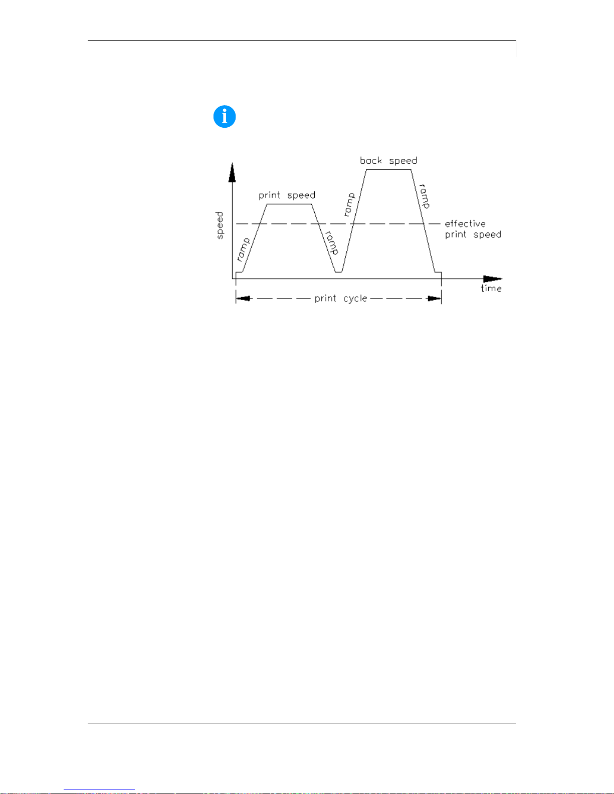
Dynacode II Series
Maintenance and Cleaning
08.16
Operating Manual
87
11.7 Cycle Optimisation (Intermittent Mode)
NOTICE!
The cycle is a finished print cycle per a unit of time.
Figure 66
In case of 'time critical' applications you have the possibility with a
good selection of different device parameters to increase the effective
print speed and it this way the clock cycle.
Generally increase the print speed.
Generally increase the back speed.
Increase acceleration and brake ramp.
Change zero point of machine.
Avoid vertical installation position of print mechanics. Install the
machine in horizontal position.
Control the short distance between printhead and print surface.
Switch off foil saving automatic.
Optimise the layout to a short print way, i.e. less blanks, no
borders at the top res. bottom, rotate the layout.


Dynacode II Series
Signal Diagrams
08.16
Operating Manual
89
12 Signal Diagrams
12.1 Continuous Mode
NOTICE!
The line 'data receipt' indicates when the direct print module
receives data.
Number of layouts per print order: 1
Data memory: standard
Ribbon save: On
Trigger input print start: increasing slope
Figure 67
In 'dispensing mode: dynamic' the layout distance onto the material is
not determined by the layout length but by the time between start
impulse and print start input.
Because of the fact that the setting 'data memory: standard' the next
print order is generated after the previous one is finished and a print
order is only finished after the feed of the complete layout, the
smallest possible time between two start impulses depends also from
the layout length.
In case the printable data is only at the beginning of the layout and the
rest of the layout is empty, then it is possible to decrease the time of
start impulse by minimising the layout length (not for 'data memory:
extended').
As soon as the generation of a layout is finished, a new one is send to
the direct print module. The time of receipt for the first layout is
normally shorter because at this time the direct print module has no
further action. At receipt of the following layout, the time of receipt is
longer because the direct print module receives data and prints at the
same time.
Dispensing mode:
Dynamic
Layout
Data receipt

Signal Diagrams
Dynacode II Series
90
Operating Manual
08.16
Number of layouts per print order: 1
Data memory: extended
Ribbon save: On
Trigger input print start: increasing slope
Figure 68
For a better comparison we used the same layouts as before.
As soon as the generation of the layout is finished a new one is send
to the direct print module.
The time of receipt for the first layout is normally shorter because at
this time the direct print module has no further action. At receipt of the
following layout, the time of receipt is longer because the direct print
module receives data and prints at the same time.
In mode 'data memory: extended' already received data is always
generated after the start of a print order.
Before the current print order is finished the next one is already
generated. The signal output is therefore active and the next start
impulse can be send.
Before the next start impulse is send, the print has to be finished as
otherwise the impulse is ignored.
Layout
Data receipt
Data receipt/
generation
Generation
Print order
Print

Dynacode II Series
Signal Diagrams
08.16
Operating Manual
91
Number of layouts per print order: 3
Data memory: Off/standard/extended
Ribbon save: On
Trigger input print start: increasing slope
Figure 69
The use of printer variables means that each layout is different and
the direct print module has to generate several parts of the layout
anew, e.g. variable counter.
Each of the 3 layouts which are to print are the same and therefore it
is only necessary to generate the layout once.
Because only 1 print order is send, the direct print module has only to
receive once.
As the print order consists of 3 layouts, the print order output is active
as long as all 3 layouts are printed.
In dispensing mode dynamic only the slope of the start impulse is
recognised as valid print start signal. However, the impulse should
have a minimum impulse width of 50 ms.
Layout/generation with
module variables
Layout/generation
without module
variables
Data receipt
Print order
Print start/print

Signal Diagrams
Dynacode II Series
92
Operating Manual
08.16
Number of layouts per print order: 4
Data memory: Off/standard/extended
Ribbon save: On
Trigger input print start: level High
Figure 70
4 layouts with counter.
In 'dispensing mode: static' the level of the start impulse is recognised
as valid start signal. In case the level is activated then the print is
continued immediately if the following layout is already generated.
After deleting the signal, the machine prints until the end of the current
layout and then the direct print module waits for the next start impulse.
Dispensing Mode:
Static
Layout
Print start/print

Dynacode II Series
Signal Diagrams
08.16
Operating Manual
93
12.2 Intermittent Mode
Figure 71
Figure 72
Mode 1
(single item
processing)
Mode 2
(continuous mode)

Signal Diagrams
Dynacode II Series
94
Operating Manual
08.16
Figure 73
Mode 4
(continuous mode,
return without 'layout
printing' signal)

Dynacode II Series
Error Correction
08.16
Operating Manual
95
13 Error Correction
Error message
Cause
Remedy
1
Line too high
Line rises up completely or
partly over the upper edge of
label.
Move line down (increase Y
value).
Check rotation and font.
2
Line too low
Line rises up completely or
partly over the bottom edge of
label.
Move line up (reduce X value).
Check rotation and font.
3
Character set
One res. several characters of
the text is res. are not available
in the selected font.
Change text.
Change font.
4
Unknown code type
Selected code is not available.
Check code type.
5
Unvalid position
Selected position is not
available.
Check position.
6
CV font
Selected font is not available.
Check font.
7
Vector font
Selected font is not available.
Check font.
8
Measuring label
While measuring no label was
found.
Set label length is too large.
Check label length and if labels
are inserted correctly.
Restart measuring anew.
9
No label found
No label available.
Soiled label photocell.
Labels not inserted correctly.
Insert new label roll.
Check if labels are inserted
correctly.
Clean the label photocell.
10
No ribbon
During the print order the
ribbon roll becomes empty.
Defect at the transfer ribbon
photocell.
Change transfer ribbon.
Check transfer ribbon photocell
(service functions).
11
COM FRAMING
Stop bit error.
Check stop bits.
Check baud rate.
Check cable (printer and PC).
12
COM PARITY
Parity error.
Check parity.
Check baud rate.
Check cable (printer and PC).
13
COM OVERRUN
Loss of data at serial interface
(RS-232).
Check baud rate.
Check cable (printer and PC).

Error Correction
Dynacode II Series
96
Operating Manual
08.16
Error message
Cause
Remedy
14
Field numer
Received line number is invalid
at RS-232 and Centronics.
Check sent data.
Check connection PC - printer.
15
Length mask
Invalid length of received mask
statement.
Check sent data.
Check connection PC - printer.
16
Unknown mask
Transferred mask statement is
invalid.
Check sent data.
Check connection PC - printer.
17
Missing ETB
No end of data found.
Check sent data.
Check connection PC - printer.
18
Invalid character
One res. several characters of
the text is res. are not available
in the selected font.
Change text.
Change font.
19
Invalid statement
Unknown transferred data
record.
Check sent data.
Check connection PC - printer.
20
Invalid check digit
For check digit control the
entered res. received check
digit is wrong.
Calculate check digit anew.
Check code data.
21
Invalid SC number
Selected SC factor is invalid for
EAN res. UPC.
Check SC factor.
22
Invalid number of
digits
Entered digits for EAN res.
UPC are invalid
< 12; > 13.
Check number of digits.
23
Check digit
calculation
Selected check digit calculation
is not available in the bar code.
Check calculation of check
digit.
Check bar code type.
24
Invalid extension
Selected zoom factor is not
available.
Check zoom factor.
25
Offset sign
Entered sign is not available.
Check offset value.
26
Offset value
Entered offset value is invalid.
Check offset value.
27
Printhead
temperature
Printhead temperature is too
high.
Defective printhead sensing
device.
Reduce contrast.
Change printhead.
28
Cutter error
With cut an error occurred.
Paper jam.
Check label run.
Check cutter run.
29
Invalid parameter
Entered data do not correspond
to the characters allowed from
the application identifier.
Check code data.

Dynacode II Series
Error Correction
08.16
Operating Manual
97
Error message
Cause
Remedy
30
Application
Identifier
Selected application identifier is
not available in GS1-128.
Check code data.
31
HIBC definition
F Missing HIBC system sign.
Missing primary code.
Check definition of HIBC code.
32
System clock
Real Time Clock function is
selected but the battery is
empty.
Defective RTC.
Change battery.
Change RTC component.
33
No CF interface
Interrupted connection CPU CF card.
Defective CF card interface.
Check connection CPU - CF
card interface.
Check CF card interface.
34
No print memory
No print CF found.
Check CF assembly on CPU.
35
Cover open
At start of a print order the
printhead is open.
Close the printhead and start
print order anew.
36
BCD invalid format
BCD error
Invalid format for the
calculation of Euro variable.
Check entered format.
37
BCD overflow
BCD error
Invalid format for the
calculation of Euro variable.
Check entered format.
38
BCD division
BCD error
Invalid format for the
calculation of Euro variable.
Check entered format.
39
FLASH ERROR
Flash component error.
Run a software update.
Change CPU.
40
Length command
Invalid length of the received
command statement.
Check data sent.
Check connection PC - printer.
41
No drive
CF card not found / not
correctly inserted.
Insert CF card correctly.
42
Drive error
Impossible to read CF card
(faulty).
Check CF card, if necessary
change it.
43
Not formatted
CF Card not formatted.
Format CF card.
44
Delete current
directory
Attempt to delete the actual
directory.
Change directory.
45
Path too long
Too long indication of path.
Indicate a shorter path.

Error Correction
Dynacode II Series
98
Operating Manual
08.16
Error message
Cause
Remedy
46
Drive writeprotected
Memory card is write-protected.
Deactivate write protection.
47
Directory not file
Attempt to indicate a directory
as file name.
Correct your entry.
48
File already open
Attempt to change a file during
an access is active.
Select another file.
49
No file/directory
File does not exist on CF card.
Check file name.
50
Invalid file name
File name contains invalid
characters.
Correct entry of name, remove
special characters.
51
Internal file error
Internal file system error.
Please contact your distributor.
52
Root full
The max. number (64) of main
directory entries is reached.
Delete at least one main
directory entry and create
subdirectories.
53
Drive full
Maximum CF capacity is
reached.
Use new CF Card, delete no
longer required files.
54
File/directory
exists
The selected file/directory
already exists.
Check name, select a different
name.
55
File too large
During copying procedure not
enough memory space onto
target drive available.
Use a larger target card.
56
No update file
Errors in update file of
firmware.
Start update file anew.
57
Invalid graphic file
The selected file does not
contain graphic data.
Check file name.
58
Directory not empty
Attempt to delete a not empty
directory.
Delete all files and subdirectories in the desired
directory.
59
No interface
No CF card drive found.
Check connection of CF card
drive.
Contact your distributor
60
No CF card
No CF card is inserted.
Insert CF card in the slot.
61
Webserver error
Error at start of web server.
Please contact your distributor.
62
Wrong FPGA
The direct print module is
equipped with the wrong
FPGA.
Please contact your distributor.
63
End position
The label length is too long.
The number of labels per cycle
is too much.
Check label length res. the
number of labels per cycle.

Dynacode II Series
Error Correction
08.16
Operating Manual
99
Error message
Cause
Remedy
64
Zero point
Defective photocell.
Change photocell.
65
Compressed air
Pressure air is not connected.
Check pressure air.
66
External releaser
External print release signal is
missing.
Check input signal.
67
Row too long
Wrong definition of column
width res. number of columns.
Reduce the column width res.
correct the number of columns.
68
Scanner
The connected bar code
scanner signals a device error.
Check the connection
scanner/printer.
Check scanner (dirty).
69
Scanner NoRead
Bad print quality.
Printhead completely soiled or
defective.
Print speed too high.
Increase contrast.
Clean printhead or exchange (if
necessary).
Reduce print speed.
70
Scanner data
Scanned data does not
correspond to the data which is
to print.
Exchange printhead.
71
Invalid page
As page number either 0 or a
number > 9 is selected.
Select a number between 1
and 9.
72
Page selection
A page which is not available is
selected.
Check the defined pages.
73
Page not defined
The page is not defined.
Check the print definition.
74
Format user guiding
Wrong format for customised
entry.
Check the format string.
75
Format date/time
Wrong format for date/time.
Check the format string.
76
Hotstart CF
No CF card found.
If option hotstart was activated,
a CF card must be inserted.
Switch off the printer before
inserting the memory card.
77
Flip/Rotate
Selection of print of several
columns and also mirror/rotate.
It is only possible to select one
of both functions.
78
System file
Loading of temporary hotstart
files.
Not possible.
79
Shift variable
Faulty definition of shift times
(overlapping times).
Check definition of shift times.
80
GS1 Databar
General GS1 Databar error.
Check definition and parameter
of GS1 Databar code.
81
IGP error
Protocol error IGP.
Check sent data.

Error Correction
Dynacode II Series
100
Operating Manual
08.16
Error message
Cause
Remedy
82
Time generation
Printing creation was still active
at print start.
Reduce print speed.
Use printers' output signal for
synchronisation.
Use bitmap fonts to reduce
generating time.
83
Transport protection
Both DPM position sensors
(start/end) are active.
Displace zero point sensor
Check sensors in service
functions menu
84
No font data
Font and web data is missing.
Run a software update.
85
No layout ID
Label ID definition is missing.
Define label ID onto the label.
86
Layout ID
Scanned data does not
correspond to defined ID.
Wrong label loaded from CF
card.
87
RFID no label
RFID unit cannot recognise a
label.
Displace RFID unit or use an
offset.
88
RFID verify
Error while checking
programmed data.
Faulty RFID label.
Check RFID definitions
89
RFID timeout
Error at programming the RFID
label.
Label positioning.
Faulty label.
90
RFID data
Faulty or incomplete definition
of RFID data.
Check RFID data definitions.
91
RFID tag type
Definition of label data does not
correspond with the used label.
Check storage partitioning of
used label type
92
RFID lock
Error at programming the RFID
label (locked fields).
Check RFID data definitions.
Label was already
programmed.
93
RFID programming
Error at programming the RFID
label.
Check RFID definitions.
94
Scanner timeout
The scanner could not read the
bar code within the set timeout
time.
Defective printhead.
Wrinkles in transfer ribbon.
Scanner wrong positioned.
Timeout time too short.
Check printhead.
Check transfer ribbon.
Position scanner correctly,
corresponding to the set
feeding.
Select longer timeout time.
 Loading...