

Carl Valentin DPM IV Service Instructions Manual


Copyright by Carl Valentin GmbH / 7968025.0519
Information on the scope of delivery, appearance, performance,
dimensions and weight reflect our knowledge at the time of printing.
We reserve the rights to make modifications.
All rights, including those regarding the translation, are reserved.
No part of this document may be reproduced in any form (print,
photocopy or any other method) or edited, copied or distributed
electronically without written permission from Carl Valentin GmbH.
Due to the constant further development of our devices discrepancies
between manual and device can occur.
Please check www.carl-valentin.de for the latest update.
Trademarks
All named brands or trademarks are registered brands or registered
trademarks of their respective owners and may not be separately
labelled. It must not be concluded from the missing labelling that it is
not a registered brand or a registered trademark.
Carl Valentin print modules comply with the following EU directives
• EG Low-Voltage Directive (2014/35/EU)
• EG Electromagnetic Compatibility Directive (2014/30/EU)
Carl Valentin GmbH
Postfach 3744
78026 Villingen-Schwenningen
Neckarstraße 78 – 86 u. 94
78056 Villingen-Schwenningen
Phone
Fax
+49 (0)7720 9712-0
+49 (0)7720 9712-9901
E-Mail
Internet
info@carl-valentin.de
www.carl-valentin.de

DPM IV
Table of Contents
05.19
Service Instructions
3
Table of Contents
Table of Contents ............................................................................. 3
1 Notes on this Document ....................................................... 5
1.1 User Notes ............................................................................... 5
1.2 Instructions .............................................................................. 5
1.3 Cross References .................................................................... 6
2 Safety Instructions ................................................................ 7
2.1 General Safety Instructions ..................................................... 7
2.2 Safety Handling when Working with Electricity ....................... 9
2.3 Environmentally-Friendly Disposal ........................................ 10
3 Retrofit with Options ........................................................... 11
3.1 Brake ..................................................................................... 11
3.2 Counter-Pressure Plate (Valentin) ........................................ 12
3.3 Protective cover for the control unit IP65 .............................. 13
4 Electronics (Replace Components) ................................... 17
4.1 Primary Fuses ....................................................................... 17
4.2 Input/Output Board ................................................................ 18
4.3 Distributor Board .................................................................... 19
4.4 CPU PCB ............................................................................... 20
4.5 Battery ................................................................................... 22
4.6 Power Supply Unit ................................................................. 23
4.7 HMI Components ................................................................... 24
5 Mechanics (Replace Components) .................................... 27
5.1 Printhead ............................................................................... 27
5.2 Transfer Ribbon Tension Adjustment .................................... 29
5.3 Angle Adjustment .................................................................. 30
5.4 Printhead Bracket .................................................................. 31
5.5 Linear Bearing for Printhead Bracket .................................... 32
5.6 Short-Stroke Cylinder ............................................................ 33
5.7 Transfer Ribbon Roller .......................................................... 34
5.8 Toothed Belt 'Motor'............................................................... 35
5.9 Linear Toothed Belt ............................................................... 36
5.10 Print Carriage ........................................................................ 38
5.11 Print Carriage PCB and Connecting Cable in the Energy Chain40
5.12 Valve ...................................................................................... 42
5.13 Zero Sensor and End Position Sensor .................................. 44
5.14 Transfer Ribbon Rewinder/Unwinder .................................... 46
5.15 Encoder ................................................................................. 48
5.16 Top Linear Bearing ................................................................ 50
5.17 Bottom Linear Bearing ........................................................... 52
5.18 Cover Sensor ......................................................................... 54
5.19 Motor PCB ............................................................................. 56
5.20 Pressure Sensor .................................................................... 58
6 Cleaning ............................................................................... 61
6.1 General Information ............................................................... 61
6.2 Transfer Ribbon Roller .......................................................... 62
6.3 Printhead ............................................................................... 63
7 Error Correction ................................................................... 65
8 Control Inputs and Outputs ................................................ 75
9 Wiring Plans ......................................................................... 83
9.1 Control Unit ............................................................................ 83
9.2 Print Mechanics (Left Version) .............................................. 84
9.3 Print Mechanics (Right Version) ............................................ 85

Table of Contents
DPM IV
4
Service Instructions
05.19
10 Layout Diagrams ................................................................. 87
10.1 CPU ....................................................................................... 87
10.2 Power Supply Unit ................................................................. 88
11 Pin Assignment of Control Unit ......................................... 89
12 Index ..................................................................................... 91
DPM IV
Notes on this Document
05.19
Service Instructions
5
1 Notes on this Document
1.1 User Notes
This service manual is intended for qualified service and maintenance
staff.
This manual contains information about the electronics and the
mechanical part of the direct print module.
Information about the operation of the direct print module can be
taken from our operating manual.
If a problem arises that cannot be solved with help of this service
instructions, then please contact your responsible distributor.
1.2 Instructions
Basic information and warning references with the corresponding
signal words for the danger level are as follows specified in this
manual:
DANGER identifies an extraordinarily great and immediate
danger which could lead to serious injury or even death.
WARNING identifies a possible danger would could lead
to serious bodily injury or even death if sufficient
precautions are not taken.
WARNING of cutting injuries.
Pay attention that cutting injuries caused by blades, cutting
devices or sharp-edged parts are avoided.
WARNING of hand injuries.
Pay attention that hand injuries caused by closing
mechanical parts of a machine/equipment are avoided.
WARNING of hot surfaces.
Pay attention so as not to come into contact with hot
surfaces.
CAUTION indicates a potentially dangerous situation
which could lead to moderate or light bodily injury or
damage to property.
NOTICE gives you tips. They make a working sequence
easier or draw attention to important working processes.
Gives you tips on protecting the environment.
Handling instruction
Optional accessories, special fittings
Date
Information in the display

Notes on this Document
DPM IV
6
Service Instructions
05.19
1.3 Cross References
References to specific items in a figure are marked with letters. They
are identified with parentheses in the text, e.g. (A). If no figure number
is provided, letters in the text always refer to the graphic directly
above the text. If a reference is made to another graphic, the figure
number is specified, e.g. (A, in figure 5).
For a cross reference to chapters and sections, the chapter number
and page number are specified, e.g. a reference to this section: see
chapter 1.3.2, page 35).
References to other documents have the following form: See
'operating manual'.
Drawings
Cross references to
chapters and sections
References to other
documents

DPM IV
Safety Instructions
05.19
Service Instructions
7
2 Safety Instructions
2.1 General Safety Instructions
Keep the area around the device clean during and after
maintenance.
Work in a safety-conscious manner.
Store dismantled device parts in a safe place while maintenance
is being performed.
CAUTION!
The drawing in of items of clothing by moving parts can
lead to injuries.
If possible, do not wear clothing which could be
caught by moving device parts.
Button or roll up shirt or jacket sleeves.
Tie or pin up long hair.
Tuck the ends of scarves, ties and shawls into your
clothing or secure them with non-conductive clips.
DANGER!
Risk of death from increased flow of current via metals
parts which come into contact with the device.
Do not wear clothing with metal parts.
Do not wear jewellery.
Do not wear glasses with a metal frame.
If a possible danger to your eyes is present, wear protective goggles,
especially in the following cases:
• when knocking in or knocking out pins and similar parts with a
hammer
• when using an electric drill
• when using spring hooks
• when loosening or inserting springs, snap rings and gripping rings
• when soldering
• when using solvents, cleaning agents or other chemicals
Workplace and
method of working
Clothing
Protective clothing

Safety Instructions
DPM IV
8
Service Instructions
05.19
WARNING!
Risk of injury in case of missing or faulty protective equipment.
After performing maintenance work, attach all safety
equipment (covers, safety precautions, ground cables etc.).
Replace faulty parts and those which have become unusable.
Examine the self-locking effect of the dust cover and if
necessary readjust at the clamp screw of the hinge.
The direct print module is designed for power supply systems of
110 V AC … 230 V AC. Connect the direct print module only to
electrical outlets with a ground contact.
NOTICE!
The protective earthing conductor of the socket is to be examined
by a qualified technician.
Couple the direct print module to devices using extra low voltage only.
Before making or undoing connections, switch off all devices involved
(computer, printer, accessories etc.).
Operate the direct print module in a dry environment only and do not
get it wet (sprayed water, mist etc.).
Do not operate the direct print module in explosive atmosphere and
not in proximity of high voltage power lines.
Operate the direct print module only in an environment protected
against abrasive dust, swarf and other similar impurity.
Maintenance and servicing work can only be carried out by trained
personnel.
Operating personnel must be trained by the operator on the basis of
the operating manual.
Depending on use, ensure that clothing, hair, jewellery and similar
personal items do not contact the exposed rotating parts and/or the
moving parts (e.g. print carriage).
The print unit and parts of it (e.g. motor, printhead) can get hot during
printing. Do not touch the printhead during operation. Cool down the
print unit before changing material, removal or adjustment.
Never use highly inflammable consumables.
Carry out only the actions described in these operating instructions.
Any work beyond this may only be performed by the manufacturer or
upon agreement with the manufacturer.
Unauthorized interference with electronic modules or their software
can cause malfunctions.
Other unauthorized work or modifications to the direct print module
can endanger operational safety.
Protective equipment
General safety
instructions

Safety Instructions
DPM IV
05.19
Service Instructions
9
There are warning stickers on the direct print modules that draw your
attention to dangers. Therefore the warning stickers are not to be
removed as then you and others cannot be aware of dangers and may
be injured.
DANGER!
Danger to life and limb from power supply!
Do not open the casing.
CAUTION!
Two-pole fuse.
Before opening the housing cover, disconnect the device from
the mains supply and wait for a moment until the power
supply unit has discharged.
2.2 Safety Handling when Working with Electricity
The following work may only be performed by instructed and
trained electricians:
• work on the electrical assemblies
• work on the device while it is open and connected to the
power supply.
Locate the emergency-stop or power switch so that it can be
actuated in case of an emergency.
Unplug the device from the electrical outlet before performing
the following work:
• removing or installing power supply units
• working in the immediate vicinity of exposed power supply
parts
• mechanical inspection of power supply parts
• modifying the device circuits.
Ensure that the device is de-energized.
Check the workplace for possible sources of danger, e.g. moist
floors, defective extension cables, faulty protective conduction
connections.
Qualifications of
personnel
General precautions to
be heeded when
beginning maintenance

Safety Instructions
DPM IV
10
Service Instructions
05.19
Give another person the task of remaining near the workplace.
This person must be familiar with the location and operation of
the emergency-stop and power switches and switch off the
power if danger arises.
Use only one hand while working on electrical circuits when a
device is switched on. Hold the other hand behind your back or
put it in your jacket pocket.
This prevents the electricity from flowing through your body.
Do not use worn or damaged tools.
Use only tools and testing equipment that is suitable for the
respective task.
Proceed in a very cautions and calm manner.
Avoid endangering yourself.
Switch the power off.
Request medical help (emergency physician).
Call for first aid if necessary.
2.3 Environmentally-Friendly Disposal
Manufacturers of B2B equipment are obliged to take back and
dispose of old equipment that was manufactured after 13 August
2005. As a principle, this old equipment may not be delivered to
communal collecting points. It may only be organised, used and
disposed of by the manufacturer. Valentin products accordingly
labelled can therefore be returned to Carl Valentin GmbH.
This way, you can be sure your old equipment will be disposed of
correctly.
Carl Valentin GmbH thereby fulfils all obligations regarding timely
disposal of old equipment and facilitates the smooth reselling of these
products. Please understand that we can only take back equipment
that is sent free of carriage charges.
The electronics board of the printing system is equipped with a
battery. This must only be discarded in battery collection containers or
by public waste management authorities.
Further information on the WEEE directive is available on our website
www.carl-valentin.de.
Additional precautions
to be heeded for
devices with exposed
energized parts
Tools
What to do in case an
accident occurs
DPM IV
Retrofit with Options
05.19
Service Instructions
11
3 Retrofit with Options
3.1 Brake
CAUTION!
Risk of injury due to short circuit.
Before opening the housing cover, disconnect the device
from the mains supply and wait for a moment until the
power supply unit has discharged.
C
D
E
F
B
G
A
H
Figure 1
1. Unscrew the six countersunk screws (H) and remove the top
cover (A).
2. Open the dust cover or remove it by unscrewing the four screws
at the hinges.
3. Insert the feather key (C) into the corresponding slot (B) at the
shaft.
4. Insert the hub (D) onto the shaft and fix it with the shaft protection
(E).
5. Remove the transport safety (rubber) from the brake (F).
6. Push the brake (F) over the hub and fasten it with the integrated
screws at the brake support, so that the cable outlet of the
connecting line is at the front motor side.
7. Insert the connecting line into the bush bearing (G) of the
distribution plate from underneath.
8. Close the dust cover and the top cover (A) and fasten it with the
six countersunk screws (H).
Retrofit with Options
DPM IV
12
Service Instructions
05.19
3.2 Counter-Pressure Plate (Valentin)
A
C
B
D
Figure 2
1. For the attachment of the optional Valentin counter-pressure plate
(A), appropriate threaded holes are designated at the bottom of
the print mechanics (D).
The suitable screws (B) are included with delivery of this option.
2. The suitable distance between the printhead and the counterpressure plate is already preset.
3. On the bottom face of the carrier of counter-pressure plate (A) are
threaded holes M4 (C), which can be used for mounting the unit
onto a plate or similar.
Retrofit with Options
DPM IV
05.19
Service Instructions
13
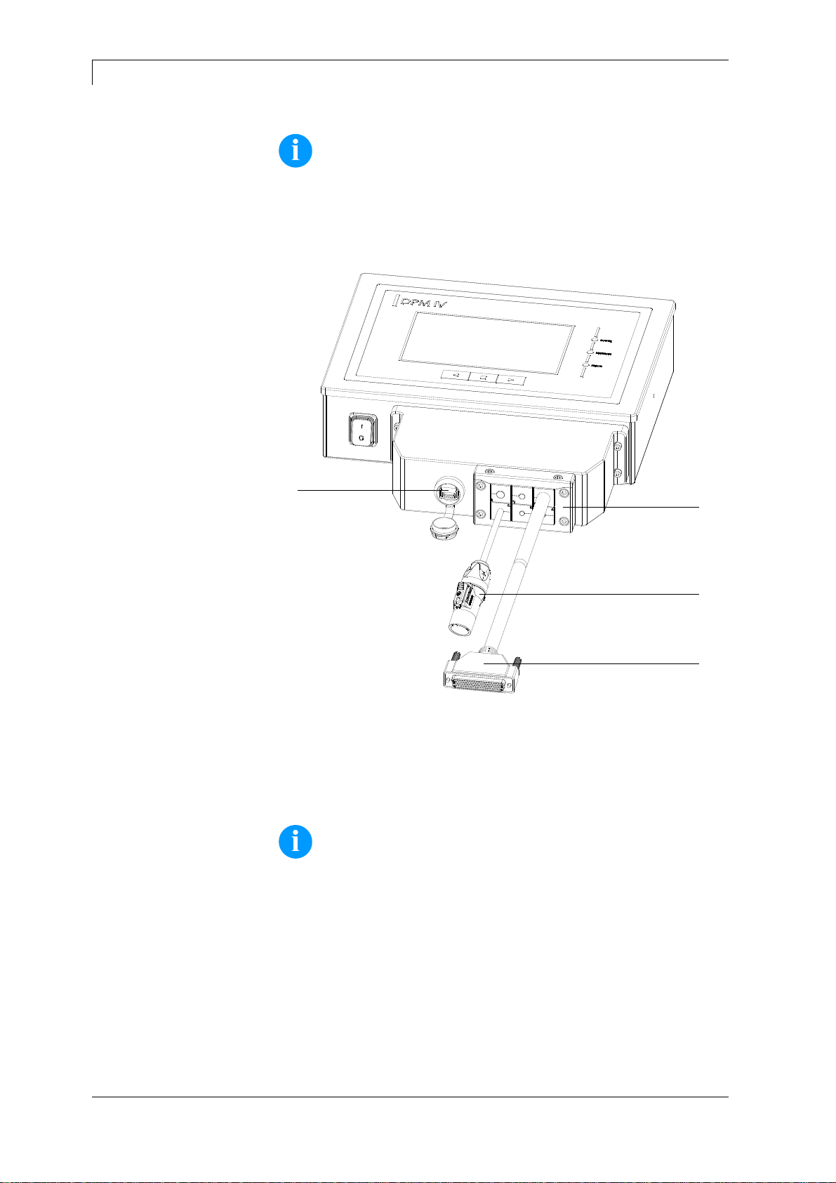
3.3 Protective cover for the control unit IP65
NOTICE!
By mounting the optional protective cover, the protection class
IP 65 according to DIN EN 60529 is achieved for the control unit
of DPM IV.
A
B
C
D
E
F
G
H
I
J
K
L
M
N
Figure 3

Retrofit with Options
DPM IV
14
Service Instructions
05.19
1. Successively remove the four screws (C) on the back on the
control unit (A), slide on the sealing rings (B) and screw in the
screws (C) again.
2. Connect the connection cable print mechanics/control unit (F) to
the control unit (A).
3. If necessary, connect a connection cable for external
inputs/outputs to the appropriate socket of the control unit (A).
4. If necessary, connect an Ethernet or USB data cable to the control
unit (A).
5. Insert the USB data cable (E) on the inside of the protective cover
(E) into the USB socket.
6. Guide the open end of the connection cable print mechanics /
control unit (F) through the opening of the protective cover (G).
The plug must be tilted sideways. Then guide the power cable (D)
and if necessary, the data and I/O cable through the opening of
the protective cover (G).
7. Guide the protective cover (G) in the direction of the control unit
(A) until the USB data cable (E) can be connected to the control
unit (A).
8. Screw the protective cover (G) to the control unit (A) with the four
screws (I) and the sealing rings (H).
9. Remove the upper part of the cable entry strip (K) after removing
the both screws (J).
10. Remove the cable grommets (M) that fit to the respective
connection cables from the cable entry strip (K) and enclose the
cables two to three centimeters in front of the protective cover (G).
11. Place the cable entry strip (K) in front of the protective cover and
insert the cable grommets (M) with connection cables into the
slots. The connection cable print mechanics/control unit (F) must
be placed in the upper right corner and the power cable (D)
should be placed on the bottom left (see Figure 4).
NOTICE!
The side of the cable entry strip (K) with the seal injected
must point in the direction of the protective cover (G).
The smooth, even sides of the grommets (M) must face
each other in the middle of the entry strip.
Unnecessary cable grommets (M) must be closed with the
enclosed suitable plugs (N).
12. Fix the upper part of the cable entry strip (K) with the screws (J),
so that the connecting cables are still movable.
13. Fix the cable entry strip (K) to the protective cover (G) with the
screws (L).
14. Screw tight the upper part of the cable entry strip (K).
Retrofit with Options
DPM IV
05.19
Service Instructions
15
NOTICE!
Check that all cables are safely enclosed by the grommets (M) so
that no water or dust can enter. Too large grommets and loose
cables lead to entering of impurities into the case.
Suitable cable grommets in different sizes are available ex works.
The size (diameter) is indicated on the respective grommet.
D
F
K
O
Figure 4
For loading of print data, the integrated USB interface (O) is
accessible from the outside.
NOTICE!
The protection class IP 65 is only achieved if the cap of the
interface is firmly closed, i.e. no USB stick or data cable is
inserted.
Do not bend the connection cable (D, F and others) directly at the
cable entry strip (K).

DPM IV
Electronics (Replace Components)
05.19
Service Instructions
17
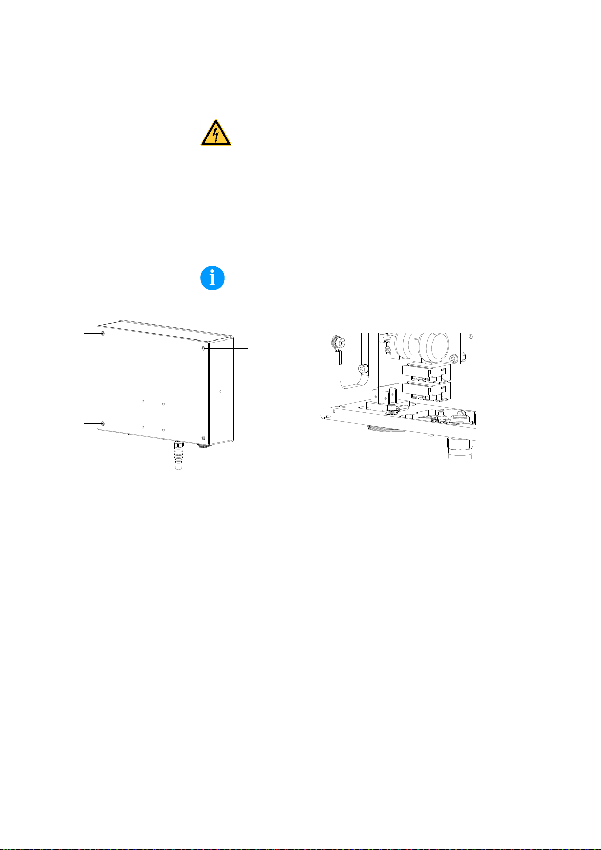
4 Electronics (Replace Components)
DANGER!
Risk of death via electric shock!
Before opening the housing cover, disconnect the device
from the mains supply and wait for a moment until the
power supply unit has discharged.
4.1 Primary Fuses
NOTICE!
The primary fuses are not accessible from the outside.
A
B
A
A
A
A
B
A
A
A
C
C
Figure 5
Figure 6
1. Unplug the control unit from the electrical outlet.
2. Unscrew the four screws (A).
3. Vertically remove the front plate (B). Disconnect disturbing
connection cables from the connectors.
4. Pull the fuse-holder (C) from the housing.
1. Replace the fuses (two T4A 250 V).
2. Push the fuse-holder (C) into the housing until it engages.
3. Reinstall the front plate (B). Plug the connection cables in.
Removing the
primary fuses
Installing the
primary fuses
Electronics (Replace Components)
DPM IV
18
Service Instructions
05.19
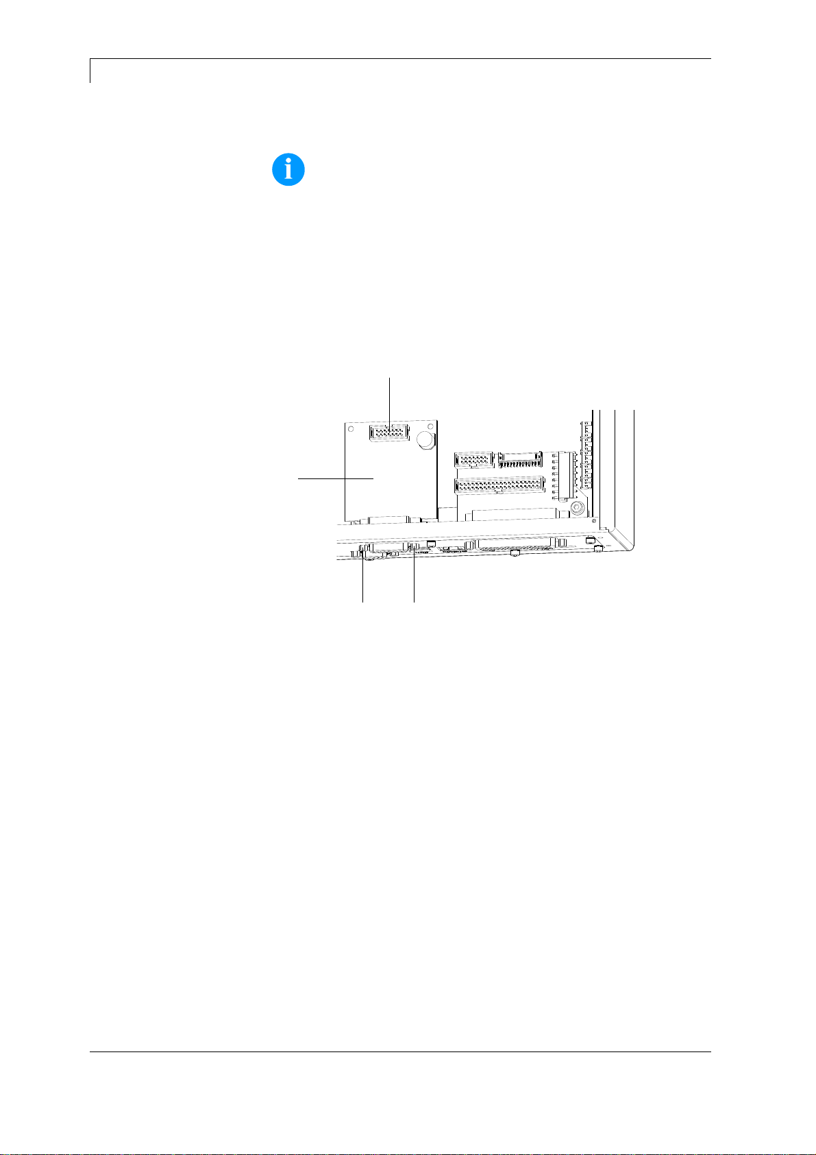
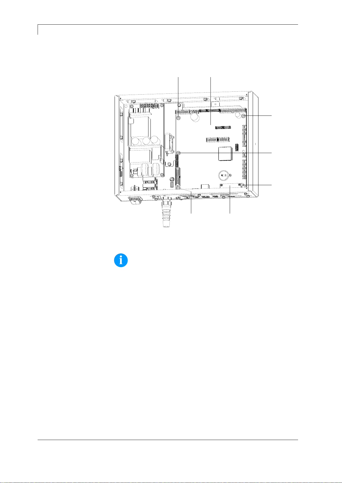
4.2 Input/Output Board
NOTICE!
The inputs/outputs can be tested in the Service Functions.
In case of an active input, the position corresponding to this input
changes to 1.
To activate an output, move the cursor to the corresponding position
and set value 1. To deactivate the output, set the corresponding
position again to 0.
Inputs and outputs marked with 'x' are not occupied.
B
C
A A
Figure 7
1. Unplug the control unit from electrical outlet.
2. Unscrew the four screws on the rear and remove the front plate
(see chapter 4.1, page 17).
3. Unscrew the retaining screws (A) at the SUB-D socket.
4. Remove the I/O plate (B) and disconnect the plug-in connector
(C).
1. Connect the new I/O board (B) with the appropriate cable (C) and
place it.
2. Fasten the retaining screws (A).
3. Reinstall the front plate.
4. Connect the power supply cable.
Removing the
input/output board
Installing the
input/output board
DPM IV
Electronics (Replace Components)
05.19
Service Instructions
19
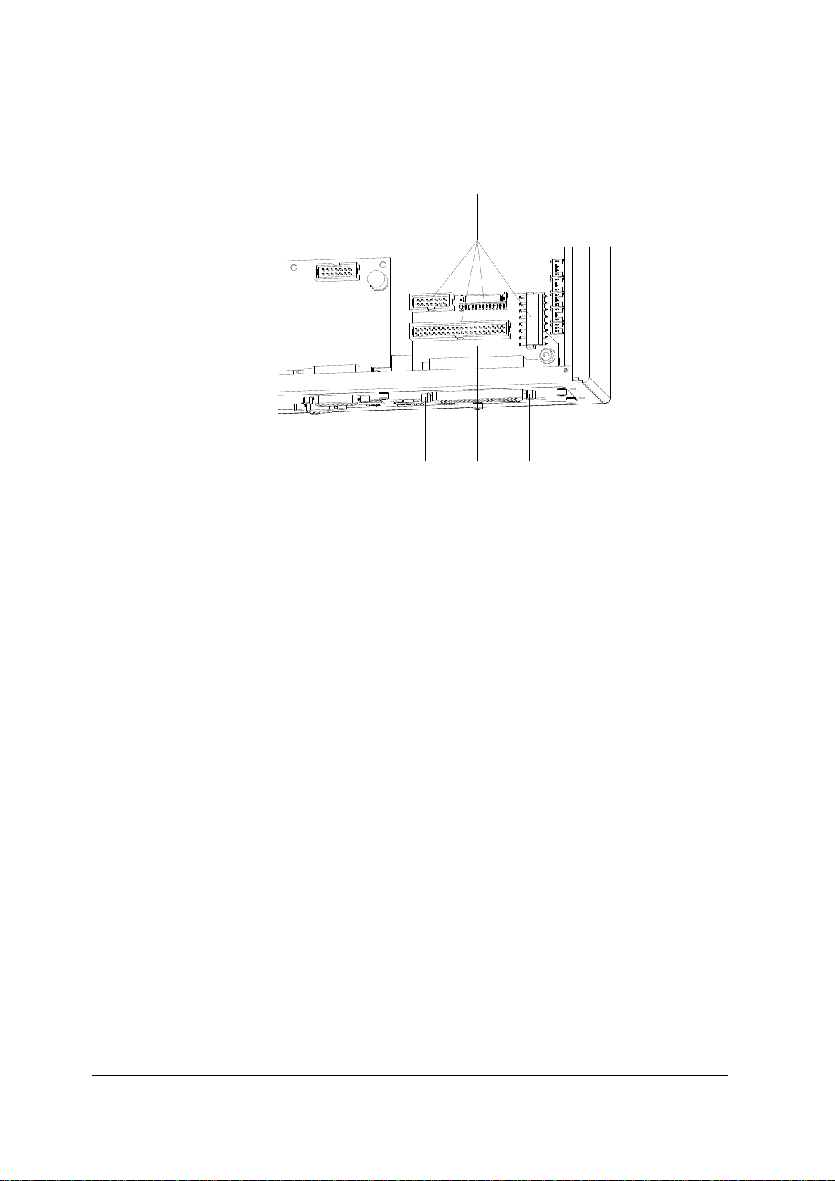
4.3 Distributor Board
A
BCB
D
Figure 8
1. Remove the control unit from the electrical outlet.
2. Unscrew the four screws on the rear and remove the front plate
(see chapter 4.1, page 17).
3. Disconnect all plug-in connectors (D) from the distributor board
(C).
4. Unscrew the retaining screws (B) at the SUB-D socket.
5. Unscrew the screw (A).
6. Remove the distributor board (C).
1. Place the new distributor board (C).
2. Fasten the retaining screws (B) and the screw (A).
3. Connect all plug-in connectors (D) with the new distributor board
(C).
4. Reinstall the front plate.
5. Connect the power supply cable.
Removing the
distributor board
Installing the
distributor board
Electronics (Replace Components)
DPM IV
20
Service Instructions
05.19
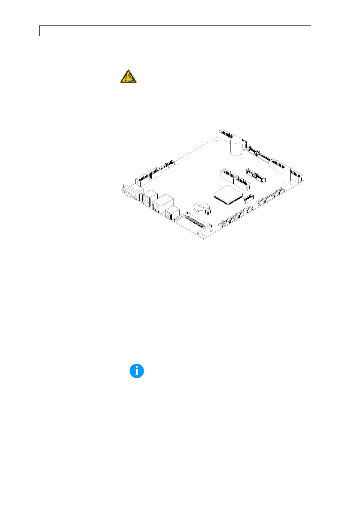
4.4 CPU PCB
A
A
B
A
A D
C
Figure 9
NOTICE!
Save the configuration onto a CF card.
1. Unplug the control unit from the electrical outlet.
2. Unscrew the four screws on the rear and remove the front plate
(see chapter 4.1, page 17).
3. Remove the distributor plate (see chapter 4.3, page 19).
4. Remove the I/O board (see chapter 4.2, page 18).
5. Disconnect all plug-in connectors from the CPU PCB (D).
6. Unscrew the screw (A).
7. Remove the six hexagonal bolts (B).
8. Carefully remove the CPU PCB (D).
Removing the
CPU PCB

DPM IV
Electronics (Replace Components)
05.19
Service Instructions
21
1. If not available, move the cover of the CF card slot (C) from the
old CPU to the new CPU.
2. Insert the CPU PCB (D) with the interface sockets into the
connection plate and turn the hexagonal bolts of the serial
interface if necessary.
3. Fasten again the PCB (D) with the screws (A) and the hexagonal
bolts (B).
4. Connect all plug-in connectors to the PCB.
5. Reinstall the I/O board (see chapter 4.2, page 18).
6. Reinstall the distributor plate (see chapter 4.3, page 19).
7. Reinstall the front plate.
8. Restore all interface connections.
9. Connect the power supply cable.
10. Check the firmware version and update it, if necessary.
11. Load the configuration from the CF card. Otherwise set the
configuration with the function menu.
Installing the
CPU PCB
Electronics (Replace Components)
DPM IV
22
Service Instructions
05.19
4.5 Battery
DANGER!
Danger of explosion due to improper replacement of the
battery!
Use non-conductive tools.
Pay attention to polarity.
A
Figure 10
1. Unplug the control unit from the electrical outlet.
2. Unscrew the four screws on the rear and remove the front plate
(see chapter 4.1, page 17).
3. Remove the distributor plate (see chapter 4.3, page 19).
4. Lift up the fixing bracket by means of a non-metallic device (e.g.
plastic ruler).
5. Remove the battery
1. Install a new battery (CR 2032) in the bracket (A).
NOTICE!
Please pay attention to the correct polarity.
2. Reinstall the distributor plate (see chapter 4.3, page 19).
3. Reinstall the front plate.
4. Connect the power supply cable.
Removing the battery
Installing the battery
DPM IV
Electronics (Replace Components)
05.19
Service Instructions
23
4.6 Power Supply Unit
A
A
A
B
B
A
B
C
B
Figure 11
1. Unplug the control unit from the electrical outlet.
2. Unscrew the four screws on the rear and remove the front panel
(see chapter 4.1, page 17).
3. Remove the plug-in connectors (B) from the power supply unit
(C).
4. Unscrew the retaining screws (A9) of the power supply unit.
Hold the power supply unit while unscrewing the retaining screws.
5. Remove the power supply unit.
1. Place the new power supply unit in the control unit housing and
tighten it with the retaining screws (A).
2. Connect the plug-in connectors (B) with the power supply unit (C).
3. Reinstall the front plate.
4. Connect the power supply cable.
Removing the power
supply unit
Installing the power
supply unit
Electronics (Replace Components)
DPM IV
24
Service Instructions
05.19
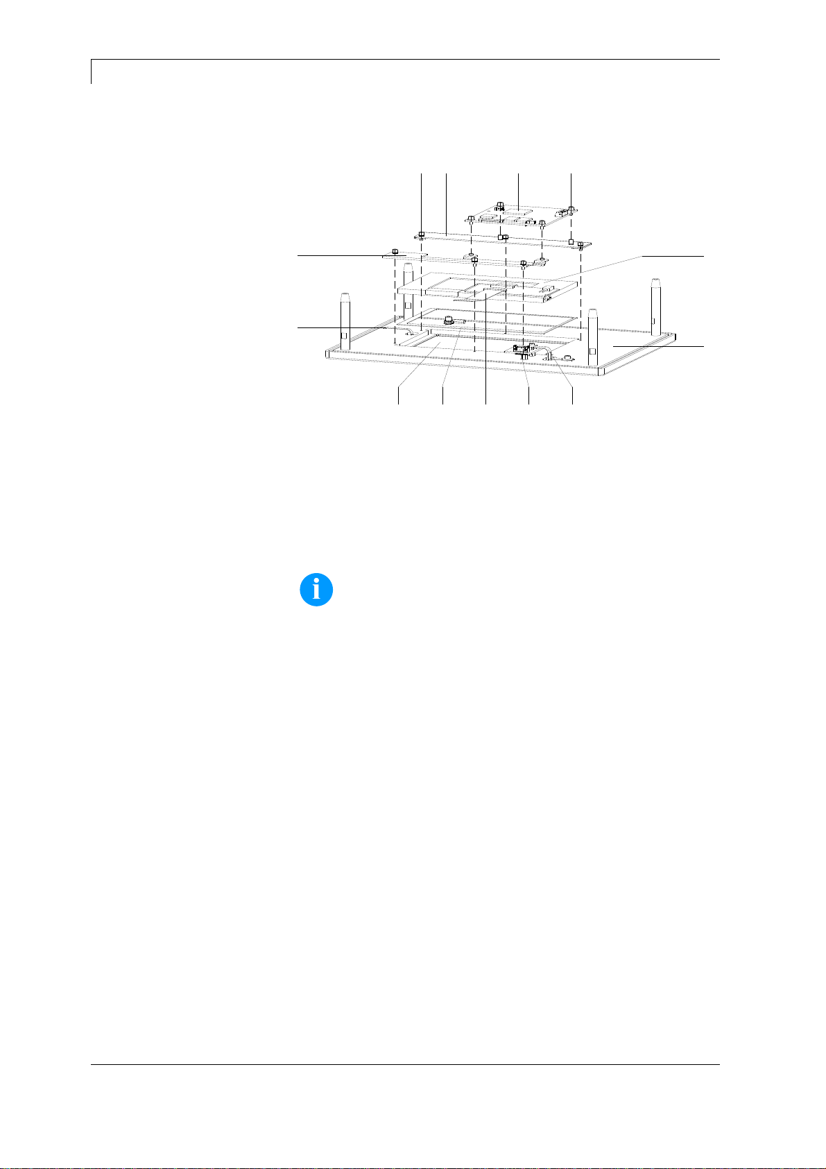
4.7 HMI Components
A
F
ML
I
KJ
B
E
H
D CG
Figure 12
1. Unplug the control unit from the electrical outlet.
2. Unscrew the four screws on the rear and remove the front plate
(B) (see chapter 4.1, page 17). Disconnect all connecting cables
at the plug-in connectors while removing the front plate.
NOTICE!
During subsequent work, take care of a dust-free atmosphere in
order to bring no unwanted particles in the field of view of the
display.
3. Carefully remove the FFC cable (E) from the plug-in connector of
the CPU HMI (L).
4. Carefully remove the connection line (H) of touch panel from the
plug-in connector of CPU HMI (L).
5. After removing the connection cable to CPU and removing the
four screws (M), remove the CPU HMI (L).
6. Remove the six screws (J).
7. Lift the top display bar (K) and the bottom display bar (I).
8. Remove the graphic module (A) and the seal (F) from the
depression.
9. The touch panel (G) laminated onto the transparent keyboard is
visible now. The touch panel is interchangeable only in
combination with the transparent keyboard.
10. After careful loosening of the connecting cable (C) and removing
the screws positioned directly next to the cable, remove the
connection board (D) for the transparent keyboard.
Removing HMI
components

DPM IV
Electronics (Replace Components)
05.19
Service Instructions
25
1. Place the connection board (D) for the transparent keyboard,
tighten the screws and plug in the connection cable (C).
2. Place the seal (F) into the depression and carefully place the new
graphic module (A) onto it.
NOTICE!
The seal (F) must be properly arranged and must not
project into the field of view of the touch panel.
3. Apply the top display bar (K) and the bottom display bar (I) on the
edge of the graphic module (A).
4. Tighten the six screws (J).
5. Insert the new CPU HMI (L), tighten the four screws (M) and plug
again the connection cable to the CPU.
6. Plug the FFC cable (E) into the plug-in connector of the CPU HMI
(L).
7. Plug all connecting cables into the plug-in connectors. Reinstall
the front plate (B) and fasten four screws on the rear.
8. Connect the power supply cable.
Installing HMI
components

Electronics (Replace Components)
DPM IV
26
Service Instructions
05.19
DPM IV
Mechanics (Replace Components)
05.19
Service Instructions
27
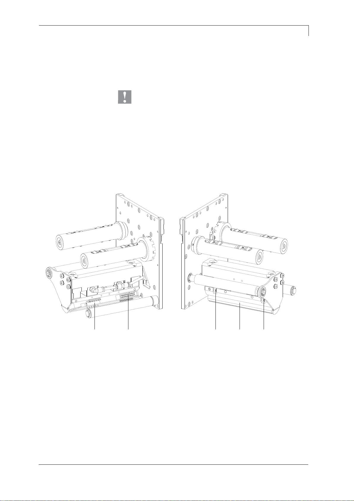
5 Mechanics (Replace Components)
5.1 Printhead
CAUTION!
The printhead can be damaged by static electricity discharges
and impacts!
Set up the direct print module on a grounded,
conductive surface.
Ground your body, e.g. by wearing a grounded
wristband.
Do not touch the contacts on the plug connections.
Do not touch the printing line with hard objects or your
hands.
ABACC
Figure 13
1. Open dust cover or remove it by unscrewing four screws at the
hinges.
2. Remove the transfer ribbon.
3. Push the print carriage into an appropriate service position.
4. Remove the printhead cable (C).
5. Remove the screws (A) and the printhead (B).
Removing the
printhead

Mechanics (Replace Components)
DPM IV
28
Service Instructions
05.19
1. Do not touch the contacts of the printhead.
2. Position the new printhead in the printhead support.
3. Tighten again the screws (A).
4. Connect the printhead cable (C).
5. Insert the transfer ribbon.
6. Enter the resistance value of the new printhead in the Service
Functions (heater resistance). The value is indicated on the type
plate of printhead.
7. Start a test print to check the printhead position.
Installing the printhead

DPM IV
Mechanics (Replace Components)
05.19
Service Instructions
29
5.2 Transfer Ribbon Tension Adjustment
ABA
Figure 14
For a regular print quality it is necessary that the transfer ribbon is to
tighten even over its width. Use the nuts (A) to regulate a different
transfer ribbon tension by a sideways overturn of the printhead.
CAUTION!
Folding at transfer ribbon!
Only change the factory settings in exceptional cases.
1. By loosen a nut, the printhead moves down at the corresponding
side.
The transfer ribbon tension is increased.
2. By tightening a nut, the printhead moves up at the corresponding
side.
The transfer ribbon tension is reduced.
NOTICE!
A strong regulation has result to the pressure power of
printhead.
3. Start a print order with approx. three layouts to check the correct
unwrinkled ribbon run.
 Loading...