

Carl Valentin DPM III xi Series, DPM III xi107, DPM III xi53, DPM III xi128 Service Instructions Manual

DPM III XI
Service Instructions

Copyright by Carl Valentin GmbH / 79670250209
Information on the scope of delivery, appearance, performance,
dimensions and weight reflect our knowledge at the time of printing.
We reserve the rights to make modifications.
All rights, including those regarding the translation, are reserved.
No part of this document may be reproduced in any form (print,
photocopy or any other method) or edited, copied or distributed
electronically without written permission from Carl Valentin GmbH.
Due to the constant further development of our devices discrepancies
between manual and device can occur.
Please check www.carl-valentin.de for the latest update.
Trademarks
All named brands or trademarks are registered brands or registered
trademarks of their respective owners and may not be separately
labelled. It must not be concluded from the missing labelling that it is
not a registered brand or a registered trademark.
Carl Valentin direct print modules comply with the following safety
guidelines:
CE
EG Low-Voltage Directive (2006/95/EC)
EG Electromagnetic Compatibility Directive (89/336/EEC)
Carl Valentin GmbH
Postfach 3744
78026 Villingen-Schwenningen
Neckarstraße 78 – 86 u. 94
78056 Villingen-Schwenningen
Phone
Fax
+49 7720 9712-0
+49 7720 9712-9901
E-Mail
Internet
info@carl-valentin.de
www.carl-valentin.de

DPM III xi series
Table of contents
0209
Service instructions
3
Table of contents
Table of contents .............................................................................. 3
1 Notes on this document ....................................................... 5
1.1 User notes ............................................................................... 5
1.2 Instructions .............................................................................. 5
1.3 Cross references ..................................................................... 6
2 Safety instructions ................................................................ 7
2.1 General safety instructions ...................................................... 7
2.2 Safety handling when working w ith elec tricity ....................... 10
3 Electronics ........................................................................... 11
3.1 Replacing primary fuse .......................................................... 11
3.2 Replacing secondary fuse ..................................................... 12
3.3 Replacing CPU PCB.............................................................. 13
3.4 Replacing printhead FPGA .................................................... 14
3.5 Replacing input/output FPGA ................................................ 14
3.6 Replacing battery................................................................... 14
3.7 Replacing power supply unit ................................................. 15
3.8 Replacing Compact Flash card slot ....................................... 16
3.9 Replacing input/output board ................................................ 17
4 Refitting options .................................................................. 19
4.1 RS-485 and RS-422 .............................................................. 19
4.2 Ethernet ................................................................................. 20
5 Mechanics ............................................................................ 21
5.1 Replacing printhead............................................................... 21
5.2 Angle adjustment ................................................................... 23
5.3 Replacing tooth belt (linear drive) .......................................... 24
5.4 Refitting brake ....................................................................... 25
5.5 Replacing zero point photocell .............................................. 26
5.6 Replacing end position photocell ........................................... 27
5.7 Adjusting ribbon drive ............................................................ 28
5.8 Adjusting ribbon tension ........................................................ 29
5.9 Lubrication ............................................................................. 30
6 Error correction ................................................................... 31
7 Control inputs and outputs ................................................ 41
7.1 Version I ................................................................................ 41
7.2 Version II ............................................................................... 45
8 Wiring plans ......................................................................... 49
8.1 Electronics ............................................................................. 49
8.2 Mechanics ............................................................................. 50
9 Layout diagrams .................................................................. 55
9.1 CPU ....................................................................................... 55
9.2 Power supply unit (revision C) ............................................... 57
9.3 Compact Flash card slot ........................................................ 59
9.4 I/O board 24V ........................................................................ 60
9.5 Ethernet ................................................................................. 62
9.6 Distributor board .................................................................... 63
9.7 Carriage board ....................................................................... 65
9.8 Motor adapter ........................................................................ 67

Table of contents
DPM III xi series
4
Service instructions
0209
10
Connection plan of back panel plugs................................ 69
10.1 Motors .................................................................................... 69
10.2 Printhead signals ................................................................... 69
10.3 Sensors ................................................................................. 70
11 Connection plan of interfaces ............................................ 71
11.1 Centronics ............................................................................. 71
11.2 RS-232 .................................................................................. 71
11.3 RS-485 and RS-422 .............................................................. 72
11.4 Ethernet ................................................................................. 73
11.5 USB 1.0 ................................................................................. 73
12 Index ..................................................................................... 75
DPM III xi series
Notes on this document
0209
Service instructions
5
1 Notes on this docume nt
1.1 User notes
This service manual is intended for qualified service and maintenance
staff.
This manual contains information about hardware and mechanical
part of the direct print module.
Information about operation of the direct print module can be taken
from our operating manual.
If a problem arises that cannot be solved with help of this service
instructions, then please contact your responsible dealer.
1.2 Instructions
Basic information and warning references with the corresponding
signal words for the danger level are as follows specified in this
manual:
DANGER identifies an extraordinarily great and immediate
danger which could lead to serious injury or even death.
WARNING identifies a possible danger would could lead
to serious bodily injury or even death if sufficient
precautions are not taken.
WARNING of cutting injuries.
Pay attention that cutting injuries caused by blades, cutting
devices or sharp-edged parts are avoided.
WARNING of hand injuries.
Pay attention that hand injuries caused by closing
mechanical parts of a machine/equipment are avoided.
WARNING of hot surfaces.
Pay attention so as not to come into contact with hot
surfaces.
CAUTION indicates a potentially dangerous situation
which could lead to moderate or light bodily injury or
damage to property.
NOTICE gives you tips. They make a working sequence
easier or draw attention to important working processes.
Gives you tips on protecting the environment.
⇒
Handling instruction
Optional accessories, special fittings
Date
Information in the display

Notes on this document
DPM III xi series
6
Service instructions
0209
DANGER!
Risk of death via electric shock!
⇒ Before opening the housing cover, disconnect the
device from the mains supply and wait approx. 2 - 3
minutes until the power supply unit has discharged.
CAUTION!
Two-pole fuse.
⇒ Before opening the housing cover, disconnect the
device from the mains supply and wait approx. 2 - 3
minutes until the power supply unit has discharged.
1.3 Cross references
References to specific items in a figure are marked with item
numbers. They are identified with parentheses in the text, e.g. (9). If
no figure number is provided, item numbers in the text always refer to
the graphic directly above the text. If a reference is made to another
graphic, the figure number is specified, e.g. (2, in figure 5).
For a cross reference to chapters and sections, the chapter number
and page number are specified, e.g. a reference to this section: see
chapter 1.3.2, on page 35).
References to other documents have the following form: See
'operating manual'.
Item numbers
Cross references to
chapters and sections
References to other
documents

DPM III xi series
Safety instructions
0209
Service instructions
7
2 Safety instructions
2.1 General safety instructions
⇒ Keep the area around the device clean during and after
maintenance.
⇒ Work in a safety-conscious m anner .
⇒ Store dismantled device parts in a safe place while maintenance
is being performed.
CAUTION!
The drawing in of items of clothing by moving parts can
lead to injuries.
⇒ If possible, do not wear clothing which could be
caught by moving device parts.
⇒ Button or roll up shirt or jacket sleeves.
⇒ Tie or pin up long hair.
⇒ Tuck the ends of scarves, ties and shawls into your
clothing or secure them with non-conductive clips.
DANGER!
Risk of death from increased flow of current via metals
parts which come into contact with the device.
⇒ Do not wear clothing with metal parts.
⇒ Do not wear jewellery.
⇒ Do not wear glasses with a metal frame.
If a possible danger to your eyes is present, wear protective goggles,
especially in the following cases:
• when knocking in or knocking out pins and similar parts with a
hammer
• when using spring hooks
• when loosening or inserting springs, snap rings and gripping rings
• when soldering
• when using solvents, cleaning agents or other chemicals
Workplace and
method of working
Clothing
Protective clothing

Safety instructions
DPM III xi series
8
Service instructions
0209
WARNING!
Risk of injury in case of missing or faulty protective
equipment.
⇒ After performing maintenance work, attach all safety
equipment (covers, safety precautions, ground cables
etc.).
⇒ Replace faulty parts and those which have become
unusable.
The direct print module is designed for power supply systems of
230 V. Connect the direct print module only to electrical outlets with a
ground contact.
NOTICE!
When changing the mains voltage the fuse value is to adapt
accordingly.
Couple the direct print module to devices using extra low voltage only.
Before making or undoing connections, switch off all devices involved
(computer, printer, accessories etc.).
Operate the direct print module in a dry environment only and do not
get it wet (sprayed water, mist etc.).
Do not operate the direct print module in explosive atmosphere and
not in proximity of high voltage power lines.
Operate the direct print module only in an environment protected
against abrasive dust, swarf and other similar impurity.
In case of cleaning and maintenance with an open cover, ensure that
clothing, hair, jewellery and similar personal items do not contact the
exposed rotating parts.
NOTICE!
With the open printing unit (due to construction) the requirements
of EN60950-1 regarding fire protection casing are not fulfilled.
These must be ensured by the installation into the en d dev ice.
The print unit can get hot during printing. Do not touch the printhead
during operation. Cool down the print unit before changing material,
removal or adjustment.
Carry out only the actions described in these operating instructions.
Any work beyond this may only be performed by the manufacturer or
upon agreement with the manufacturer.
Unauthorized interference with electronic modules or their software
can cause malfunctions.
Other unauthorized work or modifications to the direct print module
can endanger operational safety.
Always have service work done in a qualified workshop, where the
personnel have the technical knowledge and tools required to do the
necessary work.
Protective equipment
General safety
instructions

DPM III xi series
Safety instructions
0209
Service instructions
9
There are warning stickers on the direct print modules that draw your
attention to dangers. Therefore the warning stickers are not to be
removed as then you and others cannot be aware of dangers and may
be injured.
The direct printing unit must be integrated with the Em er genc y Stop
circuit when it is incorporated into the overal l m achine.
All isolating safety equipment must be installed before starting-up the
machine.
DANGER!
Danger to life and limb from power supply!
⇒ Do not open the casing.
CAUTION!
Two-pole fuse.
⇒ Before opening the housing cover, disconnect the
device from the mains supply and wait approx. 2 - 3
minutes until the power supply unit has discharged.

Safety instructions
DPM III xi series
10
Service instructions
0209
2.2 Safety handling when working with electricity
⇒ The following work may only be performed by instructed and
trained electricians:
• work on the electrical assemblies
• work on the device while it is open and connected to the
power supply.
⇒ Locate the em er genc y-stop or power switch so that it can be
actuated in case of an emergency.
⇒ Unplug the device from the electrical outlet before performing
the following work:
• removing or installing power supply units
• working in the immediate vicinity of exposed power supply
parts
• mechanical inspection of power supply parts
• modifying the device circuits.
⇒ Ensure that the devic e is de-energized.
⇒ Check the workplace for possible sources of danger, e.g. moist
floors, defective extension cables, faulty protective conduction
connections.
⇒ Give another person the task of remaining near the workplace.
This person must be familiar with the location and operation of
the emergency-stop and power switches and switch off the
power if danger arises.
⇒ Use only one hand while working on electrical circuits when a
device is switched on. Hold the other hand behind your back or
put it in your jacket pocket.
This prevents the electricity from flowing through your body.
⇒ To not use worn or damaged tools.
⇒ Use only tools and testing equipment that is suitable for the
respective task.
⇒ Proceed in a very cautions and calm manner.
⇒ Avoid endangering yourself.
⇒ Switch the power off.
⇒ Request medical help (emergency physician).
⇒ Call for first aid if necessary.
Qualifications of
personnel
General precautions to
be heeded when
beginning maintenance
Additional precautions
to be heeded for
devices with exposed
energized parts
Tools
What to do in case an
accident occurs
DPM III xi series
Electronics
0209
Service instructions
11
3 Electronics
DANGER!
Risk of death via electric shock!
⇒ Before opening the housing cover, disconnect the
device from the mains supply and wait approx. 2 - 3
minutes until the power supply unit has discharged.
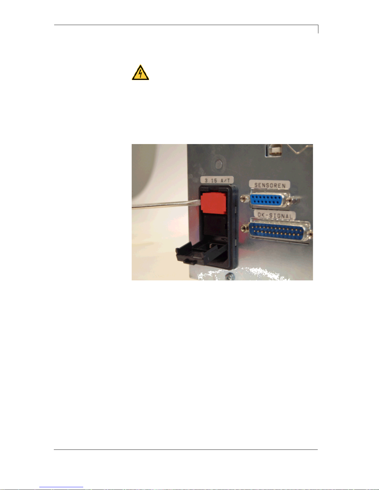
3.1 Replacing primary fuse
Figure 1
The primary fuse is in line filter block that can be accessed from
outside.
1. Unplug the machine and then open its cover.
2. Remove the fuse-holder which is behind.
3. Replace the fuse (value = 3,15A/T).
Electronics
DPM III xi series
12
Service instructions
0209
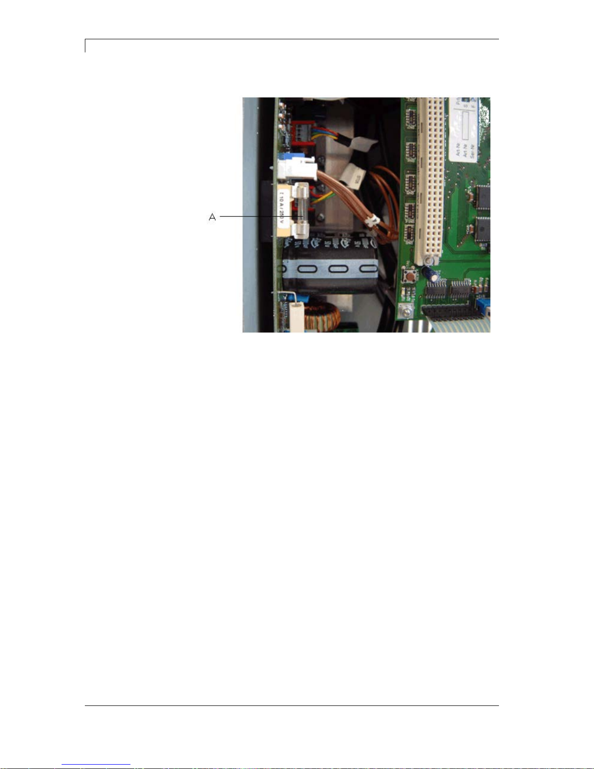
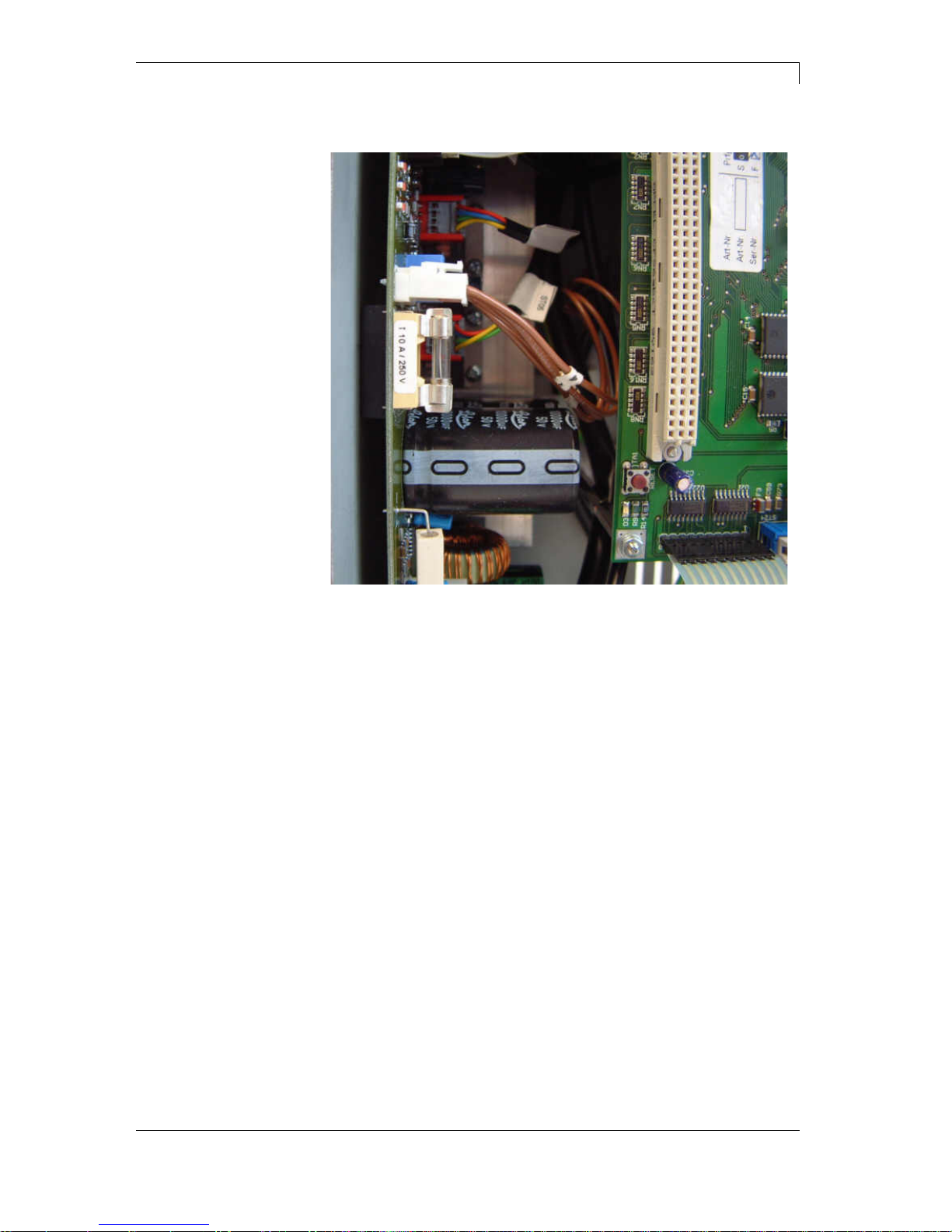
3.2 Replacing secondary fuse
Figure 2
1. Unplug the machine and then open its cover.
Now the power supply unit is visible.
2. Remove the fuse (A) which is placed on it.
F1: microfuse 10A/T = protection of all power unit voltages

DPM III xi series
Electronics
0209
Service instructions
13
3.3 Replacing CPU PCB
Figure 3
1. If possible, save the configuration of module on a Compact Flash
card.
2. Unplug the print mechanics from the electrical outlet.
3. Remove cover of control unit.
4. Detach all connections from the CPU PCB.
5. Remove fixing screws at the Centronics interface.
6. Remove all retaining screws at CPU PCB.
7. Carefully remove CPU PCB.
1. Place CPU PCB onto the retainers.
2. Secure the PCB board with screws.
3. Insert all plug connections on the PCB.
4. Restore all interface connections.
5. Connect the power cable.
6. Update the firmware if necessary.
7. If possible, load the configuration from memory card. Otherwise,
set the configuration by the function menu.
Removing the
CPU PCB
Installing the
CPU PCB

Electronics
DPM III xi series
14
Service instructions
0209
3.4 Replacing printhead FPGA
1. Remove the FPGA from the PLCC support base with suitable
displacement pincer.
2. Press the new FPGA into the support base and pay attention to
position of polarity.
3.5 Replacing input/output FPGA
1. Separate I/O board from CPU board.
Now the I/O FPGA is visible.
2. Remove the FPGA from the PLCC support base with suitable
displacement pincer.
3. Press the new FPGA into the support base and pay attention to
position of polarity.
3.6 Replacing battery
DANGER!
Danger of explosion when exchang ing the batt ery
improper.
⇒ Pay attention to polarity.
1. Lift up the fixing bracket by means of a non-metallic device (e.g.
plastic ruler).
2. Remove the battery.
3. Insert a new battery (CR 2032) into the support and pay attention
to position of polarity.
DPM III xi series
Electronics
0209
Service instructions
15
3.7 Replacing power supply unit
Figure 4
1. Unplug all connections.
2. Unscrew the screws at the rectifier Z1.
3. Remove screws at the bottom of electronics.
4. Remove the defective power suppl y unit.
5. Deposit the new power supply unit in the electronics.
Pay attention that no lines are clamped under the heat sink of
power supply unit.
6. Insert all connections in the appropriate plug-in positions.
7. Screw again the power supply unit.
Electronics
DPM III xi series
16
Service instructions
0209
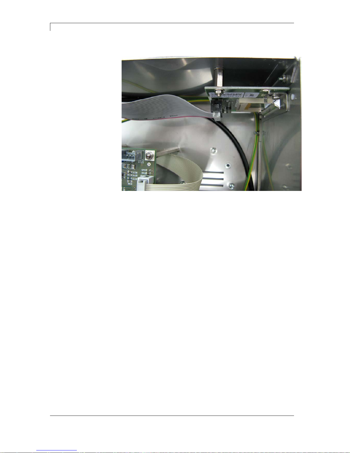
3.8 Replacing Compact Flash card slot
Figure 5
1. Remove cover of control unit.
2. Unplug connecting cable to the power supply unit at slot.
3. Unscrew retaining screws at the side panel.
4. Remove the defective slot.
5. The installation of the new slot is to be effected in reverse order.
DPM III xi series
Electronics
0209
Service instructions
17
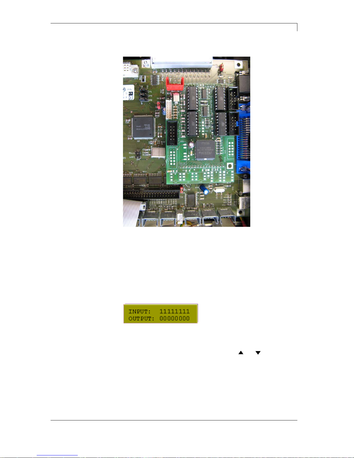
3.9 Replacing input/output board
Figure 6
1. Unplug connection cables of I/O board to the rear panel.
2. Separate defective board from CPU.
3. Insert new board.
4. Insert again the connecting cable according to wiring plan (see
chapter 8.1 on page 49).
It is possible to test the inputs/outputs in the Service Functions menu.
In case an input is activated then the position which corresponds to
this input changes to 1.
An output can be activated by positioning the cursor at the
corresponding position and then using the keys
and to set the
value to 1.
If the value is set to 0, the output is deactivated.

DPM III xi series
Refitting options
0209
Service instructions
19
4 Refitting opti ons
DANGER!
Risk of death via electric shock!
⇒ Before opening the housing cover, disconnect the
device from the mains supply and wait approx. 2 - 3
minutes until the power supply unit has discharged.
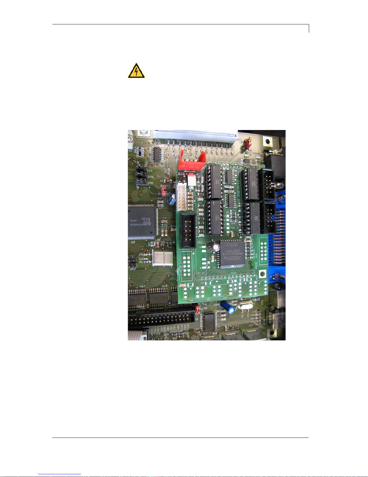
4.1 RS-485 and RS-422
Figure 7
1. Replace the installed input/output port by an input/output port
which is equipped with RS-485 or RS-422 ex tens ion.
2. Replace the line to INPUT2 by the line with 9-pin DSUB socket.
3. Insert the new line into position ST5 on the input/output plate.
4. OUTPUT1, INPUT1 and OUTPUT2 have to be installed according
to the wiring plan (see chapter 8.1 on page 49).

Refitting options
DPM III xi series
20
Service instructions
0209
4.2 Ethernet
Figure 8
1. Remove the cover of control unit.
2. Remove the screws between power unit connection (ST13) and
bus plug (ST1).
3. Screw the distance bolt M3x15 in this position.
4. Insert Ethernet plate in the break-down and insert the plate into
ST1.
5. Fix the plate with the corresponding screws.
6. Fix the plate with the already removed screw at the distance bolt.

DPM III xi series
Mechanics
0209
Service instructions
21
5 Mechanics
DANGER!
Risk of death via electric shock!
⇒ Before op en ing the ho using cover, dis con nec t the
device from the mains supply and wait approx. 2 - 3
minutes until the power supply unit has discharged.
Printing can cause accumulation of dirt at printhead e.g. by colour
particles of transfer ribbon, and therefore it is necessary to clean the
printhead in regular periods depending on operating hours,
environmental effects such as dust etc.
CAUTION!
Printhead can be damaged!
⇒ Do not use sharp or hard objects to clean the
printhead.
⇒ Do not touch protective glass layer of the printhead.
• Remove transfer ribbon material.
• Clean printhead surface with special cleaning pen or a cotton
swab dipped in pure alcohol.
• Allow printhead to dry for 2-3 minutes before commissioning the
device.
5.1 Replacing printhead
CAUTION!
The printhead can be damaged by static electricity
discharges and impacts!
⇒ Set up direct print module on a grounded, conductive
surface.
⇒ Ground your body, e.g. by wearing a grounded
wristband.
⇒ Do not touch contacts on the plug connections.
⇒ Do not touch printing line with hard objects or your
hands.
Cleaning the printhead
Mechanics
DPM III xi series
22
Service instructions
0209
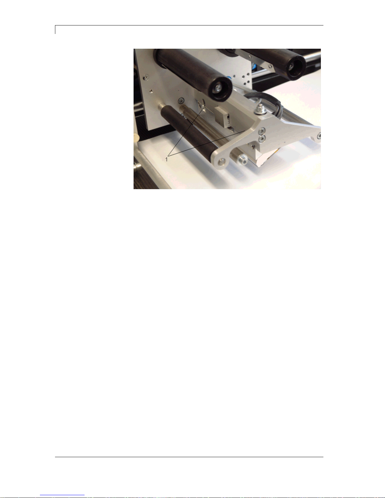
Figure 9
1. Remove transfer ribbon material.
2. Move printhead unit in an appropriate service position.
3. Remove screws (1) and afterwards the printhead.
4. Remove rear-mounted connection assembly from printhead
1. Insert connection assembly to the new printhead.
2. Hold printhead holder with a finger slightly on the pressure roll and
check the correct position of printhead.
3. Screw in screw (1) and tighten it with an Allen key.
4. Insert again transfer r ibb on material.
5. Start a test print to check printhead position.
6. Enter the resistance value of the new printh ead in the ser vice
functions (dot resistance). The value is indicated on the type plate
of printhead.
Removing the
printhead
Installing the
printhead
DPM III xi series
Mechanics
0209
Service instructions
23
5.2 Angle adjustment
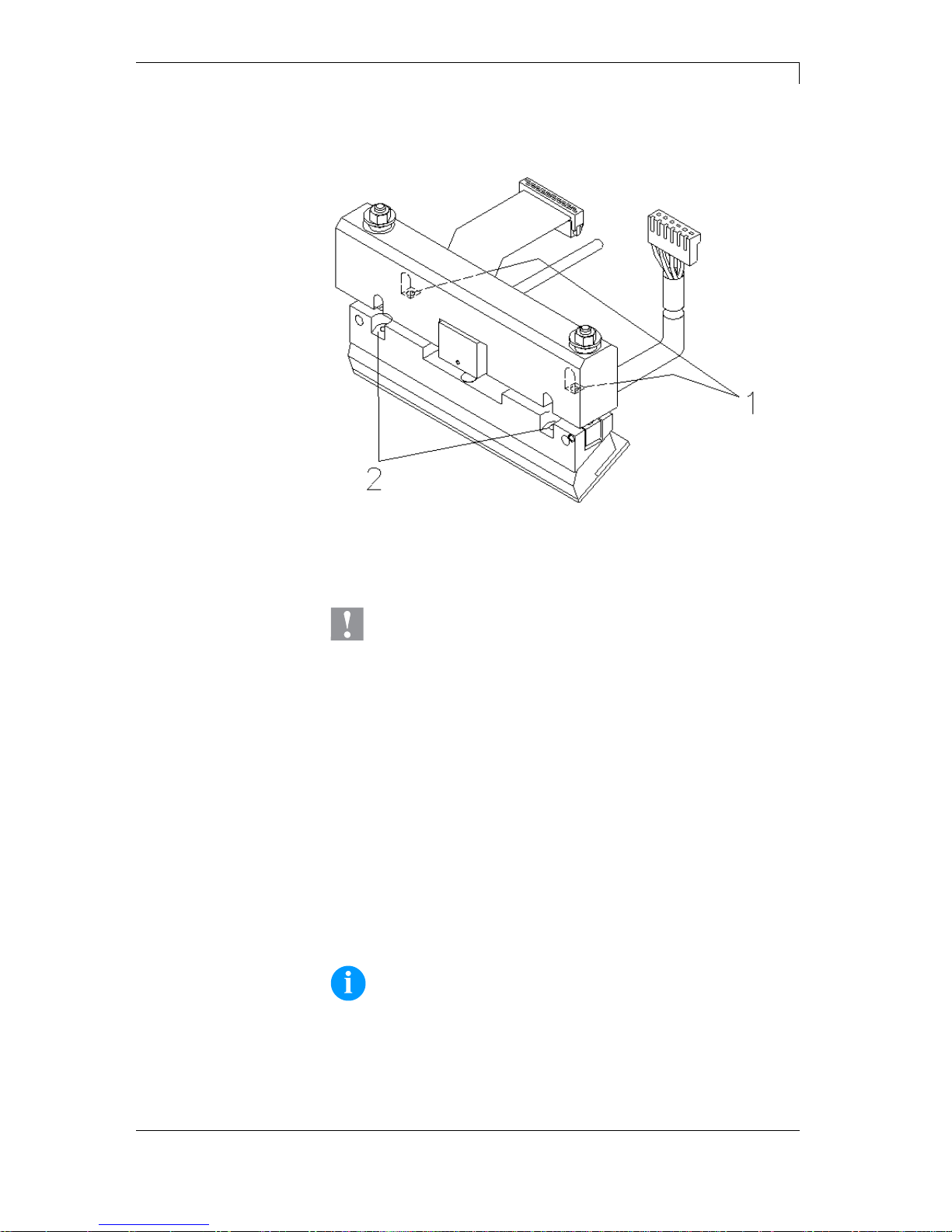
Figure 10
The installation angle of the printhead is default 26° to the print
surface. However, manufacturing tolerances of printhead and
mechanics can require another angle.
CAUTION!
Damage of printhead by unequal use!
Higher wastage of ribbon by faster ripping.
⇒ Change factory settings only in exceptional cases.
• Loosen slightly two Allen head screws (2).
• Move setscrews (1) to adjust the angle between printhead and
printhead support.
Tighten = decrease angle
Loosen = increase angle
• Beide Gewindestifte sind immer gleich weit zu verdrehen.
• Tighten again the Allen head screws (2).
• Start a print order with approx. 3 layouts to check the correct
unwrinkled ribbon run.
NOTICE!
The slots serve for position control. Pay attention to a parallel
adjustment.
Mechanics
DPM III xi series
24
Service instructions
0209
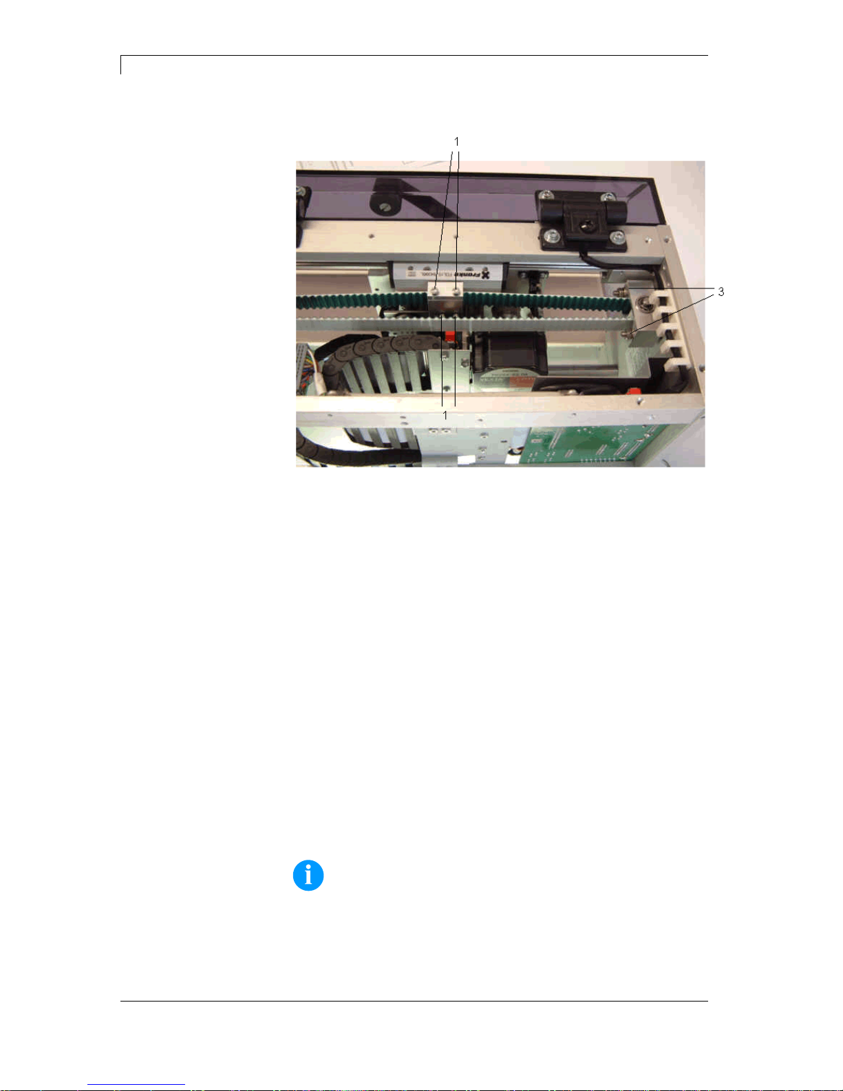
5.3 Replacing tooth belt (linear drive)
Figure 11
1. Remove 4 screws from the upper case and then remove the
cover.
2. Remove 6 screws form the cover at the back and then remove the
cover.
3. Remove 2 screws and take away the cable energy chain from the
printer carriage.
4. Remove 1 screw and 2 brass pillars and take away the distributor
board from the carriage.
It is unnecessary to unplug the connectors.
5. Loosen socket screws (1) and take away the belt support.
6. Loosen 2 socket screws and open the washer lock.
7. Remove the belt (2).
8. Remove the fixing of belt clamp (3) and loosen the belt clamp by
loosen 2 x M5 socket screws.
9. Load the new belt in the belt tightener around the carrying wheel
and the main driving pinion.
Fix it with the washer lock at the carriage.
10. Mount the washer lock and the belt support.
11. Clamp the belt with 2 x M5 socket screws and fix the belt tightener
with 2 x M5 nuts.
NOTICE!
Belt clamping:
In central position of printing carriage max. 10 mm compliance of
the belt of finger pressure.
12. The installation of all components is to be effected in reverse
order.

DPM III xi series
Mechanics
0209
Service instructions
25
5.4 Refitting brake
1. Remove 4 screws and remove the upper cover.
2. Place the brake next to the main transmission motor.
3. Tighten the brake loosely with 2 x M4x12 socket screws.
4. Hang the driving belt of brake in the main transmission motor and
brake.
5. Tighten the fixing screws of brake.
6. Insert the connecting line of brake in ST2 onto the distributor
board.
7. Mount again the upper cover.

Mechanics
DPM III xi series
26
Service instructions
0209
5.5 Replacing zero point photocell
Figure 12
1. Remove 4 screws and then the upper cover.
2. Loosen 6 screws and remove the cover at the back.
3. Remove the photocell plug ST6 onto the distributor board of the
printing carriage.
4. Loosen 2 socket screws and remove zero point photocell.
5. The installation of the new photocell is to be effected in reverse
order.
NOTICE!
The photocell must be moved in the long holes completely to the
outside (see direction of arrow).

DPM III xi series
Mechanics
0209
Service instructions
27
5.6 Replacing end position photocell
Figure 13
1. Unscrew the 4 screws and remove the upper cover.
2. Remove the photocell plug ST5 onto the distri but or boar d.
3. Unscrew 2 socket screws and remove the end position photocell.
4. The installation of the new photocell is to be effected in reverse
order.

Mechanics
DPM III xi series
28
Service instructions
0209
5.7 Adjusting ribbon drive
Figure 14
The use of another ribbon width or length can require the change of
ribbon tension.
NOTICE!
Generally:
As few ribbon tension as possible, as much as necessary!
Set the ribbon tension that no wrinkles appear in the transfer ribbon
and the ribbon is transported correctly.
1. Tighten the socket screws (1) to increase the transfer ribbon
tension.
2. Loosen the socket screws (1) to reduce the transfer ribbon
tension.
3. Start a print order with approx. 3 layouts to check the correct
unwrinkled ribbon run.

DPM III xi series
Mechanics
0209
Service instructions
29
5.8 Adjusting ribbon tension
Figure 15
For a regular print quality it is necessary that the transfer ribbon is to
tighten even over its width. With the nuts (1) it is possible to regulate a
different transfer ribbon tension by a sideways overturn of the
printhead.
CAUTION!
Folding at transfer ribbon!
⇒ Change factory settings only in exceptional cases.
1. By loosen a nut the printhead moves down at the corresponding
side.
The transfer ribbon tension is increased.
2. By tightening a nut the printhead moves up at the corresponding
side.
The transfer ribbon tension is reduced.
NOTICE!
A strong regulation has result to the pressure power of printhead.
3. Start a print order with approx. 3 layouts to check the correct
unwrinkled ribbon run.

Mechanics
DPM III xi series
30
Service instructions
0209
5.9 Lubrication
Figure 16
1. Clean the linear guiding (1) and the guiding shaft (2) with a
cleaning cloth (possibly soaked with spirits).
2. Lubricate the sections with thin oil.
3. Lubricate the guiding bearing (3) of the transfer ribbon tension roll
with thin oil.
4. Lubricate the guiding shaft (4) of the printhead bracket with thin oil
at the adjusting screws.

DPM III xi series
Error correction
0209
Service instructions
31
6 Error correction
Error message
Cause
Remedy
1
Line too high
Line rises up completely or
partly over the upper edge of
label.
Move line down (increase Y
value).
Check rotation and font.
2
Line too low
Line rises up completely or
partly over the bottom edge of
label.
Move line up (reduce Y value).
Check rotation and font.
3
Character set
One res. several characters of
the text is res. are not available
in the selected font.
Change text.
Change font.
4
Unknown code type
Selected code is not available.
Check code type.
5
Unvalid position
Selected position is not
available.
Check position.
6
CV font
Selected font is not available.
Check font.
7
Vector font
Selected font is not available.
Check font.
8
Measuring label
While measuring no label was
found.
Set label length is too large.
Check label length and if labels
are inserted correctly.
Restart measuring anew.
9
No label found
No label available.
Soiled label photocell.
Labels not inserted correctly.
Insert new label roll.
Check if labels are inserted
correctly.
Clean the label photocell.
10
No ribbon
During the print order the
ribbon roll becomes empty.
Defect at the transfer ribbon
photocell.
Change transfer ribbon.
Check transfer ribbon photocell
(service functions).
11
COM FRAMING
Stop bit error.
Check stop bits.
Check baud rate.
Check cable (printer and PC).
12
COM PARITY
Parity error.
Check parity.
Check baud rate.
Check cable (printer and PC).
13
COM OVERRUN
Loss of data at serial interface
(RS-232).
Check baud rate.
Check cable (printer and PC).

Error correction
DPM III xi series
32
Service instructions
0209
Error message
Cause
Remedy
14
Field numer
Received line number is invalid
at RS-232/parallel interf ac e.
Check sent data.
Check connection PC - printer.
15
Length mask
Invalid length of received mask
statement.
Check sent data.
Check connection PC - printer.
16
Unknown mask
Transferred mask statement is
invalid.
Check sent data.
Check connection PC - printer.
17
Missing ETB
No end of data found.
Check sent data.
Check connection PC - printer.
18
Invalid character
One res. several characters of
the text is res. are not available
in the selected font.
Change text.
Change font.
19
Invalid statement
Unknown transferred data
record.
Check sent data.
Check connection PC - printer.
20
Invalid check digit
For check digit control the
entered res. received check
digit is wrong.
Calculate check digit anew.
Check code data.
21
Invalid SC number
Selected SC factor is invalid for
EAN res. UPC.
Check SC factor.
22
Invalid number of
digits
Entered digits for EAN res.
UPC are invalid
< 12; > 13.
Check number of digits.
23
Check digit
calculation
Selected check digit calculation
is not available in the bar code.
Check calculation of check
digit.
Check bar code type.
24
Invalid extension
Selected zoom factor is not
available.
Check zoom factor.
25
Offset sign
Entered sign is not available.
Check offset value.
26
Offset value
Entered offset value is invalid.
Check offset value.
27
Printhead
temperature
Printhead temperature is too
high.
Defective printhead sensing
device.
Reduce contrast.
Change printhead.
28
Cutter error
With cut an error occurred.
Paper jam.
Check label run.
Check cutter run.
29
Invalid parameter
Entered data do not correspond
to the characters allowed from
the application identifier.
Check code data.

DPM III xi series
Error correction
0209
Service instructions
33
Error message
Cause
Remedy
30
Application
Identifier
Selected application identif ier is
not available in GS1-128.
Check code data.
31
HIBC definition
F Missing HIBC system sign.
Missing primary code.
Check definition of HIBC code.
32
System clock
Real Time Clock function is
selected but the battery is
empty.
Defective RTC.
Change battery.
Change RTC component.
33
No CF interface
Interrupted connection CPU -
CF card.
Defective CF card interface.
Check connection CPU - CF
card interface.
Check CF card interface.
34
No print memory
No print CF found.
Check CF assembly on CPU.
35
Printhead open
At start of a print order the
printhead is open.
Close the printhead and start
print order anew.
36
BCD invalid format
BCD error
Invalid format for the
calculation of Euro variable.
Check entered format.
37
BCD overflow
BCD error
Invalid format for the
calculation of Euro variable.
Check entered format.
38
BCD division
BCD error
Invalid format for the
calculation of Euro variable.
Check entered format.
39
FLASH ERROR
Flash component error.
Run a software update.
Change CPU.
40
Length command
Invalid length of the received
command statement.
Check data sent.
Check connection PC - printer.
41
No drive
CF card not found / not
correctly inserted.
Insert CF card correctly.
42
Drive error
Impossible to read CF card
(faulty).
Check CF card, if necessary
change it.
43
Not formatted
CF Card not formatted.
Format CF card.
44
Delete current
directory
Attempt to delete the actual
directory.
Change directory.
45
Path too long
Too long indication of path.
Indicate a shorter path.

Error correction
DPM III xi series
34
Service instructions
0209
Error message
Cause
Remedy
46
Drive write-
protected
Memory card is write-protected.
Deactivate write protection.
47
Directory not file
Attempt to indicate a directory
as file name.
Correct your entry.
48
File already open
Attempt to change a file during
an access is active.
Select another file.
49
No file/directory
File does not exist on CF card.
Check file name.
50
Invalid file name
File name contains invalid
characters.
Correct entry of name, remove
special characters.
51
Internal file error
Internal file system error.
Please contact your distributor.
52
Root full
The max. number (64) of main
directory entries is reached.
Delete at least one main
directory entry and create
subdirectories.
53
Drive full
Maximum CF capacity is
reached.
Use new CF Card, delete no
longer required files.
54
File/directory
exists
The selected file/directory
already exists.
Check name, select a different
name.
55
File too large
During copying procedure not
enough memory space onto
target drive available.
Use a larger target card.
56
No update file
Errors in update file of
firmware.
Start update file anew.
57
Invalid graphic file
The selected file does not
contain graphic data.
Check file name.
58
Directory not empty
Attempt to delete a not empty
directory.
Delete all files and sub-
directories in the desired
directory.
59
No interface
No CF card drive found.
Check connection of CF card
drive.
Please contact your distributor
60
No CF card
No CF card is inserted.
Insert CF card in the slot.
61
Webserver error
Error at start of web server.
Please contact your distributor.
62
Wrong FPGA
The direct print module is
equipped with the wrong
FPGA.
Please contact your distributor.
63
End position
The label length is too long.
The number of labels per cycle
is too much.
Check label length res. the
number of labels per cycle.

DPM III xi series
Error correction
0209
Service instructions
35
Error message
Cause
Remedy
64
Zero point
Defective photocell.
Change photocell.
65
Compressed air
Pressure air is not connected.
Check pressure air.
66
External releaser
External print release signal is
missing.
Check input signal.
67
Row too long
Wrong definition of column
width res. number of columns.
Reduce the column width res.
correct the number of columns.
68
Scanner
The connected bar code
scanner signals a device error.
Check the connection
scanner/printer.
Check scanner (dirty).
69
Scanner NoRead
Bad print quality.
Printhead completely soiled or
defective.
Print speed too high.
Increase contrast.
Clean printhead or exchange (if
necessary).
Reduce print speed.
70
Scanner data
Scanned data does not
correspond to the data which is
to print.
Exchange printhead.
71
Invalid page
As page number either 0 or a
number > 9 is selected.
Select a number between 1
and 9.
72
Page selection
A page which is not available is
selected.
Check the defined pages.
73
Page not defined
The page is not defined.
Check the print definition.
74
Format user guiding
Wrong format for customised
entry.
Check the format string.
75
Format date/time
Wrong format for date/time.
Check the format string.
76
Hotstart CF
No CF card found.
If option hotstart was activated,
a CF card must be inserted.
Switch off the printer before
inserting the memory card.
77
Flip/Rotate
Selection of print of several
columns and also mirror/rotate.
It is only possible to select one
of both functions.
78
System file
Loading of temporary hotstart
files.
Not possible.
79
Shift variable
Faulty definition of shift times
(overlapping times).
Check definition of shift times.
80
GS1 Databar
General GS1 Databar error.
Check definition and parameter
of GS1 Databar code.
81
IGP error
Protocol error IGP.
Check sent data.

Error correction
DPM III xi series
36
Service instructions
0209
Error message
Cause
Remedy
82
Time generation
Printing creation was still active
at print start.
Reduce print speed.
Use printers' output signal for
synchronisation.
Use bitmap fonts to reduce
generating time.
83
Transport protection
Both DPM position sensors
(start/end) are active.
Displace zero point sensor
Check sensors in service
functions menu
84
No font data
Font and web data is missing.
Run a software update.
85
No layout ID
Label ID definition is missing.
Define label ID onto the label.
86
Layout ID
Scanned data does not
correspond to defined ID.
Wrong label loaded from CF
card.
87
RFID no label
RFID unit cannot recognise a
label.
Displace RFID unit or use an
offset.
88
RFID verify
Error while checking
programmed data.
Faulty RFID label.
Check RFID definitions
89
RFID timeout
Error at programming the RFID
label.
Label positioning.
Faulty label.
90
RFID data
Faulty or incomplete definition
of RFID data.
Check RFID data definitions.
91
RFID tag type
Definition of label data does not
correspond with the used label.
Check storage partitioning of
used label type
92
RFID lock
Error at programming the RFID
label (locked fields).
Check RFID data definitions.
Label was already
programmed.
93
RFID programming
Error at programming the RFID
label.
Check RFID definitions.
94
Scanner timeout
The scanner could not read the
bar code within the set timeout
time.
Defective printhead.
Wrinkles in transfer ribbon.
Scanner wrong positioned.
Timeout time too short.
Check printhead.
Check transfer ribbon.
Position scanner correctly,
corresponding to the set
feeding.
Select longer timeout time.

DPM III xi series
Error correction
0209
Service instructions
37
Error message
Cause
Remedy
95
Scanner layout
difference
Scanner data does not
correspond to bar code data.
Check adjustment of scanner.
Check scanner settings /
connection.
96
COM break
Serial interface error.
Check settings for serial data
transmission as well as cable
(printer-PC).
97
COM general
Serial interface error.
Check settings for serial data
transmission as well as cable
(printer-PC).
98
No software
printhead FPGA
No printhead-FPGA data
available.
Please contact your
responsible distributor.
99
Load software
printhead FPGA
Error when programming
printhead-FPGA.
Please contact your
responsible distributor.
100
Upper position
Sensor signal up is missing
(option APL 100).
Check input signals /
compressed-air supply.
101
Lower position
Sensor signal down is missing
(option APL 100).
Check input signals /
compressed-air supply.
102
Vacuum plate empty
Sensor does not recognise a
label at vacuum plate
(option APL 100).
Check input signals /
compressed-air supply.
103
Start signal
Print order is active but device
not ready to process it.
Check start signal.
104
No print data
Print data outside the defined
label.
Selection of wrong module type
(design software).
Check selected module type.
Check selection of left/right
version.
105
Printhead
No original printhead is used.
Check the used printhead.
Contact your distributor.
106
Invalid Tag type
Wrong Tag type.
Tad data do not match the Tag
type in the printer.
Adapt data or use the correct
Tag type.
107
RFID invalid
RFID module is not activated.
No RFID data can be
processed.
Activate RFID module or
remove RFID data from label
data.
108
GS1-128 invalid
Transferred GS1-128 bar code
is invalid.
Verify bar code data (see GS1-
128 bar code specification).
109
EPC parameter
Error at EPC calculation.
Verify data (see EPC
specification).

Error correction
DPM III xi series
38
Service instructions
0209
Error message
Cause
Remedy
110
Housing open
When starting the print order
the housing cover is not closed.
Close the housing cover and
start the print order anew.
111
EAN.UCC code
Transferred EAN.UCC code is
invalid.
Verify bar code data (see
corresponding specification).
112
Print carriage
Printing carriage does not
move.
Check gear belt (possibly
broken).
113
Applicator error
Error while using applicator.
Check applicator.
114
Left position
Left final position switch is not
in correct position.
Check LEFT final position
switch for correct function and
position.
Check function of pneumatics
for cross traverse.
115
Right position
Right final position switch is not
in correct position.
Check RIGHT final position
switch for correct function and
position.
Check function of pneumatics
for cross traverse.
116
Print position
The print position is not correct.
Check TOP and RIGHT final
position switch for correct
function and position.
Check pneumatics for function
117
XML parameter
The parameters in the XML file
are not correct.
Please contact your
responsible distributor.
118
Invalid variable
Transferred variable is invalid
with customized entry.
Select correct variable without
customized entry and transfer
it.
119
No ribbon
During the print order the
ribbon roll becomes empty.
Defect at the transfer ribbon
photocell.
Change transfer ribbon.
Check transfer ribbon photocell
(service functions).
120
Wrong directory
Invalid target directory when
copying.
Target directory must not be
within the source directory.
Check target directory.
121
No label found
No label found at the rear
printhead (DuoPrint).
Soiled label photocell.
Labels not inserted correctly.
Insert new label roll.
Clean the label photocell.
Check if labels are inserted
correctly.
122
IP occupied
The IP address was already
assigned.
Assign a new IP address.

DPM III xi series
Error correction
0209
Service instructions
39
Error message
Cause
Remedy
123
Print asynchronous
The label photocell does not
work in the order as it is
expected according to print
data.
Check label size and gap size.
The settings of the photocell
are not correct.
Check label photocell settings.
Settings of label size and gap
size are not correct.
Check correct loading of label
material.
No label found at the rear
printhead.
Insert new label roll.
Soiled label photocell.
Clean the label photocell.
Labels not inserted correctly.
Check if labels are inserted
correctly.
124
Speed too slow.
The print speed is too slow.
Increase the speed of
customers' machine.
125
DMA send buffer
Communication problem HMI.
Restart the printer.
126
UID conflict
Configuration RFID
programming faulty.
Run RFID initialising.
127
Module not found
RFID module not available.
Check the RFID module
connection.
Please contact your
responsible distributor.
128
No release signal
No print release by higher-level
control (customer machine).
Activate release signal at the
higher-level control.
129
Wrong firmware
Firmware does not match the
used printer type.
Use firmware that fits to the
printer type.
Please contact your
responsible distributor.
130
Language missing
Language file for the set printer
language is not available.
Please contact your
responsible distributor.
131
Wrong material
Label material does not fit to
printing data.
User label material with
suitable label and/or gap
length.
132
Invalid mark-up tag
Invalid mark-up formatting
characters in text.
Correct the formatting
characters in the text.
133
Script not found
LUA script file not found.
Check the file name.
134
Script failure
LUA script is incorrect.
Check the script.

Error correction
DPM III xi series
40
Service instructions
0209
Error message
Cause
Remedy
135
Script user error
Error in LUA script user input.
Correct the input value.
136
No reprint available
No label data for reprinting
available.
Send new label data to the
printer.
137
Printhead short
circuit
Electrical short at the printhead.
Check the used printhead.
Please contact your distributor.
138
Too little ribbon
Transfer ribbon ends.
Change transfer ribbon.

DPM III xi series
Control inputs and outputs
0209
Service instructions
41
7 Control inputs and outputs
7.1 Version I
Figure 17
A = External output 1-4 (Output I)
B = External input 1-4 (Input I)
C = External output 5-8 (Output II)
D = External input 5-8 (Input II)
By means of the signal outputs different operating states of the print
module can be queried.
The signal outputs are provided by two 9-pin SUB-D-bushings
(OUTPUT I and OUTPUT II) on the back side of the control unit.
They consist of optocoupler semiconductor sections, which are
connected through and/or blocked according to different operating
states.
The maximum allowable current in a semiconductor section is
lmax = 30 mA.
Output I
Figure 17, A
Figure 18
PIN (bushing) Output I
Out 1: Error message
Each error status such as ribbon
error is displayed.
Out 2: Print order
The print module was activated by
a print order.
Out 3: Generation
The print module is filled with
current layout data.
Out 4: Layout print
The content of print memory is
transferred on the printable medium
by means of the printhead.
Plug connection - back
side of control unit
Control outputs

Control inputs and outputs
DPM III xi series
42
Service instructions
0209
Connection of a lamp to a 24V relay by Out 1:
Figure 19
Output II
Figure 17, C
Figure 20
PIN (bushing) Output II
Out 5: Print-Ready signal
It is indicated if the print module is
ready to process a start impulse. In
contrary to the print order signal, the
generating time is taken into
consideration.
Out 6: Printhead up
The printhead has reached the upper
rest position (e.g. return to zero
point).
Out 7: Return to start
After termination of print procedure
the flexible part of the print module is
moved back to the start position.
After the start position was reached a
new start can be released.
Out 8: Prior warning of transfer
ribbon end
Example

DPM III xi series
Control inputs and outputs
0209
Service instructions
43
By means of the control inputs it is possible to control printing. The
control inputs at Input I are electroplated separated and have to be
provided with an external tension source. The signal level is active
"HIGH".
Input I
Figure 17, B
Figure 21
PIN (pin) Input I
In 1: Print start
In 2: Not used
In 3: Reset external counter
In 4: Not used
Connection of a switch with 24V voltage supply by In 1:
Figure 22
Control inputs
Example

Control inputs and outputs
DPM III xi series
44
Service instructions
0209
Input II
Figure 17, D
Figure 23
PIN (pin) Input II
In 5: Not used
In 6: Not used
In 7: Not used
In 8: Not used

DPM III xi series
Control inputs and outputs
0209
Service instructions
45
7.2 Version II
Figure 24
A = External output 1-4 (Output I)
B = External input 1-4 (Input I)
C = External output 5-8 (Output II)
D = External bushing 15pin (I/O-24)
By means of the signal outputs different operating states of the print
module can be queried.
The signal outputs are provided by two 9-pin SUB-D-bushings
(OUTPUT I and OUTPUT II) on the back side of the control unit.
They consist of optocoupler semiconductor sections, which are
connected through and/or blocked according to different operating
states.
The maximum allowable current in a semiconductor section is
lmax = 30 mA.
Output I
Figure 24, A
Figure 25
PIN (bushing) Output I
Out 1: Error message
Each error status such as ribbon
error is displayed.
Out 2: Print order
The print module was activated by a
print order.
Out 3: Generation
The print module is filled with current
layout data.
Out 4: Layout print
The content of print memory is
transferred on the printable medium
by means of the printhead.
Plug connection - back
side of control unit
Control outputs

Control inputs and outputs
DPM III xi series
46
Service instructions
0209
Connection of a lamp to a 24V relay by Out 1:
Figure 26
Output II
Figure 24, C
Figure 27
PIN (bushing) Output II
Out 5: Print-Ready signal
It is indicated if the print module is
ready to process a start impulse. In
contrary to the print order signal, the
generating time is taken into
consideration.
Out 6: Printhead up
The printhead has reached the upper
rest position (e.g. return to zero
point).
Out 7: Return to start
After termination of print procedure
the flexible part of the print module is
moved back to the start position.
After the start position was reached a
new start can be released.
Out 8: Prior warning of transfer
ribbon end
Example

DPM III xi series
Control inputs and outputs
0209
Service instructions
47
By means of the control inputs it is possible to control printing. The
control inputs at Input I are galvanic separated and have to be
provided with an external tension source. The signal level is active
"HIGH".
Input I
Figure 24, B
Figure 28
PIN (pin) Input I
In 1: Print start
In 2: Not used
In 3: Reset external counter
In 4: Not used
Connection of a switch with 24V voltage supply by In 1:
Figure 29
Control inputs
Example

Control inputs and outputs
DPM III xi series
48
Service instructions
0209
External bushing I/O-24
Figure 24, D
This input is executed as 15-pole and provides user-
sided 24V/100mA.
In case of using this bushing, exists no galvanic
separation.
Figure 30
PIN
Function
1, 6
Gnd
5, 10
24 V / 100 mA
3
Print start (NPN initiator)
2
Print start (PNP initiator)
4
Print start by
potential-free
contact
14
7
Signal lamp
24 V / 100 mA
(error)
13
Example 1
Example 2
Example 3

DPM III xi series
Wiring plans
0209
Service instructions
49
8 Wiring plans
8.1 Electronics
Figure 31

Wiring plans
DPM III xi series
50
Service instructions
0209
8.2 Mechanics
Figure 32
DPM III xi53
right version

DPM III xi series
Wiring plans
0209
Service instructions
51
Figure 33
DPM III xi53
left version

Wiring plans
DPM III xi series
52
Service instructions
0209
Figure 34
DPM III xi107 + xi128
right version

DPM III xi series
Wiring plans
0209
Service instructions
53
Figure 35
DPM III xi107 + xi128
left version


DPM III xi series
Layout diagrams
0209
Service instructions
55
9 Layout diagra m s
9.1 CPU
Figure 36

Layout diagrams
DPM III xi series
56
Service instructions
0209
JP1
JP2
JP3
JP4
JP5
JP6
JP7
BOOT
1-2
open
closed
1-2
closed
open
open
2 charging
circuits
2-3
open
open
1-2
closed
closed
closed
JP8
JP9
JP10
JP11
JP12
JP13
JP14
BOOT
1-2
1-2 - 1-2
1-2
open
open
2 charging
circuits
2-3
2-3
1-2
2-3
2-3
closed
1-2
Bausteine ICs:
U1; U2
FLASH memory
U3
32 Bit RISC CPU
U5; U6
DRAM
U8
RESET component
U10
RTC (Real Time Clock)
U11
Input/Output FPGA
U13
RS-232 component
U14
USB (Universal Serial Bus) component
U20
Printhead FPGA
U28
Serial EEPROM
ST1
Bus plug
ST5
Combined sensor signals
ST9
Zero position photocell
ST10
End position photocell
ST11
Cover switch
ST12
Compressed-air control
ST13
Connection to power unit
ST15
Transfer ribbon control
ST16, 17, 19
I/O, RS-485, RS-422 (Option)
ST20
Memory Card
ST21
Foil keyboard
ST22
Printhead KCE107/12 and KCE 53/12
ST24
LCD display
Jumper plan
Component overview
Plug-in positions

DPM III xi series
Layout diagrams
0209
Service instructions
57
9.2 Power supply unit (revision C)
Figure 37

Layout diagrams
DPM III xi series
58
Service instructions
0209
U7
Motor driver ribbon motor
U13
Motor driver feed motor
U16
Control component printhead heater voltage
U17
Voltage control 5V
U18
Voltage control 24V
Z1
Bridge-connected rectifier
F1
Secondary fuse 10A/T
T2
P canal MOS-FET 100V/50A printhead voltage
ST3
Motor plug ribbon motor
ST5
Motor plug feed motor
ST6
Heater voltage printhead
ST7
Toroidal transformer
ST9
Connection CPU
ST10
Fan
ST11
24V/Brake/Valve
5V
Voltage for CPU (VCC)
24V
Heater voltage printhead (VDK)
40V
Input voltage (VIN)
GND
Mass
Component overview
Plug-in positions
Measuring points

DPM III xi series
Layout diagrams
0209
Service instructions
59
9.3 Compact Flash card slot
Figure 38
The following Compact Flash cards can be used:
• 512 MB
• 1 GB
• 2 GB

Layout diagrams
DPM III xi series
60
Service instructions
0209
9.4 I/O board 24V
Figure 39
Only valid for complete equipped I/O plate
Function
Jumper position JP6
RS-422
full duplex
2-1
RS-485
half duplex
2-3
I/O board with
external sensor
Jumper plan

DPM III xi series
Layout diagrams
0209
Service instructions
61
U1
EPLD Component
U2
Optocoupler outputs 1-4 (Output1)
U3
Optocoupler outputs 5-8 (Output2)
U4
Optocoupler inputs 1-4 (Input1)
U5
Optocoupler inputs 5-8 (Input2)
U6
Driver inputs
U7
Driver RS-422 / RS-485
U8
Optocoupler DTR/DIR
U9
Optocoupler TXD1
U10
Optocoupler RXD1
U11
Voltage transformer 5V ±5V
U20, 21
Interface components RS-422 / RS-485
ST1
Outputs 1-4 (Output1)
ST2
Outputs 5-8 (Output2)
ST3
Inputs 1-4 (Input 1)
ST4
Inputs 5-8 (Input2)
ST5
RS-485 / RS-422
ST 16, 17, 19
Connection CPU
Component overview
Plug-in positions

Layout diagrams
DPM III xi series
62
Service instructions
0209
9.5 Ethernet
Figure 40

DPM III xi series
Layout diagrams
0209
Service instructions
63
9.6 Distributor board
Figure 41
ST5
Feed motor
ST6
Heater voltage for KCE 53/12
ST10
End point photocell
ST14
Cover switch
ST12
Compressed-air control
ST19
Brake
ST21
Option encoder
ST22
Motor signals from electronics
ST23
Printhead signals from electronics
ST24
Sensor signals from electronics
ST27
Connection carriage plate
ST28
Motor signals from electronics
ST29
Printhead signals from electronics
Right version
Plug-in positions

Layout diagrams
DPM III xi series
64
Service instructions
0209
Figure 42
ST5
Feed motor
ST6
Heater voltage for KCE 53/12
ST10
Final point photocell
ST14
Cover switch
ST12
Compressed-air control
ST19
Brake
ST21
Option encoder
ST22
Motor signals from electronics
ST23
Printhead signals from electronics
ST24
Sensor signals from electronics
ST27
Connection carriage plate
ST28
Motor signals from electronics
ST29
Printhead signals from electronics
Left version
Plug-in positions

DPM III xi series
Layout diagrams
0209
Service instructions
65
9.7 Carriage board
Figure 43
ST1
KCE 53/12
ST2
KCE 107/12
ST3
Transfer ribbon motor
ST4
Valve
ST5
Connection distributor plate
ST6
Transfer ribbon control
ST7
Zero point photocell
Right version
Plug-in positions

Layout diagrams
DPM III xi series
66
Service instructions
0209
Figure 44
ST1
KCE 53/12
ST2
KCE 107/12
ST3
Transfer ribbon motor
ST4
Valve
ST5
Connection distributor plate
ST6
Transfer ribbon control
ST7
Zero point photocell
Left version
Plug-in positions

DPM III xi series
Layout diagrams
0209
Service instructions
67
9.8 Motor adapter
Figure 45
ST1
Connection distributor plate
ST2
Brake
ST4
Feed motor
ST5
Final point photocell
Right version
Plug-in positions

Layout diagrams
DPM III xi series
68
Service instructions
0209
Figure 46
ST1
Connection distributor plate
ST2
Brake
ST4
Feed motor
ST5
Final point photocell
Left version
Plug-in positions

DPM III xi series
Connection plan of back panel plugs
0209
Service instructions
69
10 Connec t ion plan of back panel plugs
10.1 Motors
Figure 47
PIN
Signal
1-2; 14-15
FEED motor
5
24V 6 Control signal VALVE
18
Control signal BRAKE
7-8; 19-20
RIBBON motor
10.2 Printhead signals
Figure 48
PIN
Signal
1, 14
5V
2, 10, 15, 16, 17, 18
GND
3
DATAIN
4
CLOCK
5
/LATCH
6
B.E.O.
7
/STR2
8
/CONT2
9
/CONT4
19
/STR1
20
/CONT1
21
/CONT3
22
/CONT5
23
THERM

Connection plan of back panel plugs
DPM III xi series
70
Service instructions
0209
10.3 Sensors
Figure 49
PIN
Signal
2,8
GND
10
5V
3, 11
RIBBONCTRL, PULLUP (transfer ribbon photocell)
4, 12
HEADDOWN, GND (Compressed-air control)
5, 13
FEEDCTRL, PULLUP (Zero point photocell)
6, 14
TCREND, PULLUP (Final point photocell)
1, 9
HEADCLOSE, PULLUP (Cover switch)

DPM III xi series
Connection plan of interfaces
0209
Service instructions
71
11 Connec t ion plan of interfaces
11.1 Centronics
Figure 50
PIN
Signal
1
STROBE
2-9
DATA1-8
10
ACK
11
BUSY
12
PERROR
13
SELECT
14
AUTOFD
15-16
GND
18
VCC1284 (4,7V)
19-30
GND
31
INIT
32
FAULT
33-35
XXX
36
SELECTIN
11.2 RS-232
Figure 51
PIN
Signal
1
XXX
2
RXD
3
TXD
4-5
GND
6-9
XXX

Connection plan of interfaces
DPM III xi series
72
Service instructions
0209
11.3 RS-485 and RS-422
Figure 52
PIN at
D-SUB
socket
Function RS-422
(full duplex)
Function RS-485
(half duplex)
1
n/c n/c 2
n/c n/c 3
n/c n/c 4 TxD−
n/c 5 TxD+
n/c 6
n/c
TxD (RTxD)−
7
n/c
TxD (RxD)+
8 RxD−
n/c 9 RxD+
n/c

DPM III xi series
Connection plan of interfaces
0209
Service instructions
73
11.4 Ethernet
Figure 53
PIN RJ45socket
Description
1 TX+
2 TX−
3 RX+
4
n/c 5
n/c 6 RX−
7
n/c 8
n/c
11.5 USB 1.0
12
3 4
Figure 54
PIN
Signal
1
n/c 2 D− 3 D+ 4 GND


DPM III xi series
Index
0209
Service instructions
75
12 Index
A
Adjusting
Ribbon drive .................................................................................... 28
Ribbon tension ................................................................................ 29
Angle adjustment ................................................................................ 23
B
Battery, replacing ............................................................................... 14
Brake, refitting .................................................................................... 25
C
Carriage board, left version
Layout diagram ............................................................................... 66
Plug-in positions ............................................................................. 66
Carriage board, right version
Layout diagram ............................................................................... 65
Plug-in positions ............................................................................. 65
Centronics, connection plan (interfaces) ............................................ 71
Compact Flash card
Replacing slot ................................................................................. 16
Slot, layout diagram ........................................................................ 59
Component overview
CPU ................................................................................................ 56
I/O board 24V ................................................................................. 61
Power suppl y unit ........................................................................... 58
Connection plan, back panel plugs
Motors ............................................................................................. 69
Printhead signals ............................................................................ 69
Sensors ........................................................................................... 70
Connection plan, interfaces
Centronics ....................................................................................... 71
Ethernet .......................................................................................... 73
RS-232 ............................................................................................ 71
RS-422 ............................................................................................ 72
RS-485 ............................................................................................ 72
USB 1.0........................................................................................... 73
CPU
Component overview ...................................................................... 56
Jumper plan .................................................................................... 56
Layout diagram ............................................................................... 55
Plug-in positions ............................................................................. 56
Replacing ........................................................................................ 13
D
Distributor board, left version
Layout diagram ............................................................................... 64
Plug-in positions ............................................................................. 64
Distributor board, right version
Layout diagram ............................................................................... 63
Plug-in positions ............................................................................. 63
E
Electricity, safety handling .................................................................. 10

Index
DPM III xi series
76
Service instructions
0209
Electronics
Battery, replacing ............................................................................ 14
Compact Flash card slot, replacing ................................................ 16
CPU PCB replacing ........................................................................ 13
I/O board, replacing ........................................................................ 17
I/O FPGA, replacing ........................................................................ 14
Power suppl y unit, replacing ........................................................... 15
Primary fuse, replacing ................................................................... 11
Printhead FPGA, replacing ............................................................. 14
Secondary fuse, replacing .............................................................. 12
Electronics, wiring plan ....................................................................... 49
Error messages/corrections ............................................................... 40
Error messages/Error corrections 31, 32, 33, 34, 35, 36, 37, 38, 39, 40
Ethernet
Layout diagram ............................................................................... 62
Refit options .................................................................................... 20
Ethernet, connection plan (interfaces) ............................................... 73
F
Final position photocell, replacing ...................................................... 27
I
I/O board 24V
Component overview ...................................................................... 61
Jumper plan .................................................................................... 60
Layout diagram ............................................................................... 60
Plug-in positions ............................................................................. 61
I/O board, replacing ............................................................................ 17
I/O FPGA, replacing ........................................................................... 14
Inputs/outputs ........................................... 41, 42, 43, 44, 45, 46, 47, 48
J
Jumper plan
CPU ................................................................................................ 56
I/O board 24V ................................................................................. 60
L
Layout diagrams
Carriage board, left version ............................................................ 66
Carriage board, right version .......................................................... 65
Compact Flash card slot ................................................................. 59
CPU ................................................................................................ 55
Distributor board, left version .......................................................... 64
Distributor board, right version ....................................................... 63
Ethernet .......................................................................................... 62
I/O board 24V ................................................................................. 60
Motor adapter, left version .............................................................. 68
Motor adapter, right version ............................................................ 67
Power suppl y unit ........................................................................... 57
Lubrication .......................................................................................... 30
M
Measuring points, power supply unit .................................................. 58
Mechanics
Brake, refitting ................................................................................. 25
Final position photocell, replacing .................................................. 27
Lubrication ...................................................................................... 30

DPM III xi series
Index
0209
Service instructions
77
Printhead, replacing .................................................................. 21, 22
Ribbon drive, adjusting ................................................................... 28
Ribbon tension, adjusting ............................................................... 29
Tooth belt (linear drive), replacing .................................................. 24
Zero point photocell, replacing ....................................................... 26
Motor adapter, left version
Layout diagram ............................................................................... 68
Plug-in positions ............................................................................. 68
Motor adapter, right version
Layout diagram ............................................................................... 67
Plug-in positions ............................................................................. 67
Motors, connection plan (back panel plugs)....................................... 69
N
Notes
Document ......................................................................................... 5
User .................................................................................................. 5
Warnings ........................................................................................... 5
O
Options, refit
Ethernet .......................................................................................... 20
RS-485/RS-422 .............................................................................. 19
P
Plug-in positions
Carriage board, left version ............................................................ 66
Carriage board, right version .......................................................... 65
CPU ................................................................................................ 56
Distributor board, left version .......................................................... 64
Distributor board, right version ....................................................... 63
I/O board 24V ................................................................................. 61
Motor adapter, left version .............................................................. 68
Motor adapter, right version ............................................................ 67
Power suppl y unit ........................................................................... 58
Power suppl y unit
Component overview ...................................................................... 58
Layout diagram ............................................................................... 57
Measuring points ............................................................................ 58
Plug-in positions ............................................................................. 58
Replacing ........................................................................................ 15
Primary fuse, replacing ....................................................................... 11
Printhead
Printhead FPGA, replacing ............................................................. 14
Replacing .................................................................................. 21, 22
Signals, connection plan (back panel plugs) .................................. 69
R
Refitting, brake ................................................................................... 25
Replacing
Battery............................................................................................. 14
Compact Flash card slot ................................................................. 16
CPU PCB ........................................................................................ 13
Final position photocell ................................................................... 27
I/O board ......................................................................................... 17
I/O FPGA ........................................................................................ 14
Power suppl y unit ........................................................................... 15

Index
DPM III xi series
78
Service instructions
0209
Primary fuse .................................................................................... 11
Printhead .................................................................................. 21, 22
Printhead FPGA .............................................................................. 14
Secondary fuse ............................................................................... 12
Tooth belt (linear drive) ................................................................... 24
Zero point photocell ........................................................................ 26
Ribbon
Adjusting drive ................................................................................ 28
Adjusting tension ............................................................................ 29
RS-232, connection plan (interfaces) ................................................. 71
RS-422, connection plan (interfaces) ................................................. 72
RS-485, connection plan (interfaces) ................................................. 72
RS-485/RS-422, refit options ............................................................. 19
S
Safety handling when working with elec tr ic ity .................................... 10
Safety instructions ............................................................................ 8, 9
Clothing ............................................................................................. 7
Protective clothing ............................................................................ 7
Protective equipment ........................................................................ 8
Workplace ......................................................................................... 7
Secondary fuse, replacing .................................................................. 12
Sensors, connection plan (back panel plugs) .................................... 70
T
Tooth belt (linear drive), replacing ...................................................... 24
U
USB 1.0, connection plan (interfaces) ................................................ 73
W
Warnings .............................................................................................. 5
Wiring plans
Electronics ...................................................................................... 49
Mechanics (DPM III xi107 left version) ........................................... 53
Mechanics (DPM III xi107 right version) ......................................... 52
Mechanics (DPM III xi128 left version) ........................................... 53
Mechanics (DPM III xi128 right version) ......................................... 52
Mechanics (DPM III xi53 left version) ............................................. 51
Mechanics (DPM III xi53 right version) ........................................... 50
Z
Zero point photocell, replacing ........................................................... 26


Carl Valentin GmbH
Neckarstraße 78 – 86 u. 94 . 78056 Villingen-Schwenningen
Phone +49 7720 9712-0 . Fax +49 7720 9712-9901
info@carl-valentin.de . www.carl-valentin.de
 Loading...