


Copyright by Carl Valentin GmbH / 7967005A.0418
Information on the scope of delivery, appearance, performance,
dimensions and weight reflect our knowledge at the time of printing.
We reserve the rights to make modifications.
All rights, including those regarding the translation, are reserved.
No part of this document may be reproduced in any form (print,
photocopy or any other method) or edited, copied or distributed
electronically without written permission from Carl Valentin GmbH.
Due to the constant further development of our devices discrepancies
between manual and device can occur.
Please check www.carl-valentin.de for the latest update.
Trademarks
All named brands or trademarks are registered brands or registered
trademarks of their respective owners and may not be separately
labelled. It must not be concluded from the missing labelling that it is
not a registered brand or a registered trademark.
Carl Valentin direct print modules comply with the following safety
guidelines:
CE
EG Low-Voltage Directive (2006/95/EC)
EG Electromagnetic Compatibility Directive (89/336/EEC)
Carl Valentin GmbH
Postfach 3744
78026 Villingen-Schwenningen
Neckarstraße 78 – 86 u. 94
78056 Villingen-Schwenningen
Phone
Fax
+49 7720 9712-0
+49 7720 9712-9901
E-Mail
Internet
info@carl-valentin.de
www.carl-valentin.de

DPM III xi series
Table of contents
04.18
Operating manual
3
Table of contents
Table of contents .............................................................................. 3
1 Introduction ............................................................................ 5
1.1 General Instructions ................................................................ 5
1.2 Intended Use ........................................................................... 5
1.3 Safety Instructions ................................................................... 6
2 Machine Overview ................................................................. 9
2.1 Print Mechanics ....................................................................... 9
2.2 Connector Assignment of Control Unit .................................. 10
2.3 Connector Assignment of Control Unit IP Version ................ 11
2.4 Print Principle ........................................................................ 12
3 Operating Conditions .......................................................... 13
4 Technical Data ..................................................................... 17
4.1 Control Inputs and Outputs (Standard) ................................. 18
4.2 Control Inputs and Outputs (Option) ..................................... 23
5 Installation and Initiation .................................................... 27
5.1 Installation of Print Mechanics at Machines .......................... 28
5.2 Connection of Pneumatic Power Supply ............................... 29
5.3 Adjustment of Pressure Power .............................................. 30
5.4 Connecting the Direct Print Module ....................................... 31
5.5 Before Initial Operation .......................................................... 31
5.6 Print Control ........................................................................... 32
5.7 Initiation ................................................................................. 32
5.8 Loading Transfer Ribbon ....................................................... 33
6 Foil Keyboard ....................................................................... 35
6.1 Keyboard Assignment (Standard) ......................................... 35
6.2 Keyboard Assignment (Text Entry/Customized/Memory Card)
36
7 Function Menu ..................................................................... 39
7.1 Menu Structure ...................................................................... 39
7.2 Print Settings ......................................................................... 41
7.3 Machine Parameters ............................................................. 42
7.4 Layout Settings ...................................................................... 45
7.5 Ribbon Save .......................................................................... 46
7.6 Device Settings ...................................................................... 47
7.7 I/O Parameters ...................................................................... 49
7.8 Network (DPM IIIxi optional only) .......................................... 50
7.9 Interface ................................................................................. 51
7.10 Emulation ............................................................................... 52
7.11 Date & Time ........................................................................... 53
7.12 Service Functions .................................................................. 54
7.13 Main Menu ............................................................................. 56
8 Compact Flash Card............................................................ 57
9 Maintenance and Cleaning ................................................. 63
9.1 General Cleaning................................................................... 63
9.2 Cleaning the Transfer Ribbon Drawing Roller ....................... 64
9.3 Cleaning the Printhead .......................................................... 64
9.4 Replacing the Printhead ........................................................ 65
9.5 Transfer Ribbon Tension ....................................................... 66
9.6 Angle Adjustment .................................................................. 67
9.7 Zero Point Adjustment ........................................................... 68
9.8 Print Quality Optimisation ...................................................... 69
9.9 Cycle Optimisation................................................................. 70

Table of contents
DPM III xi series
4
Operating manual
04.18
10 Signal Diagrams .................................................................. 71
10.1 Mode 1 (single item processing) ........................................... 71
10.2 Mode 2 (continuous mode) .................................................... 72
10.3 Mode 4 (continuous mode) .................................................... 73
10.4 Mode 8 (single item processing) ........................................... 74
11 Error Correction ................................................................... 75
12 Additional Information ........................................................ 85
12.1 Column Printing ..................................................................... 85
12.2 Hotstart .................................................................................. 86
12.3 Password ............................................................................... 88
13 Environmentally-Friendly Disposal ................................... 91
14 Index ..................................................................................... 93
DPM III xi series
Introduction
04.18
Operating manual
5
1 Introduction
1.1 General Instructions
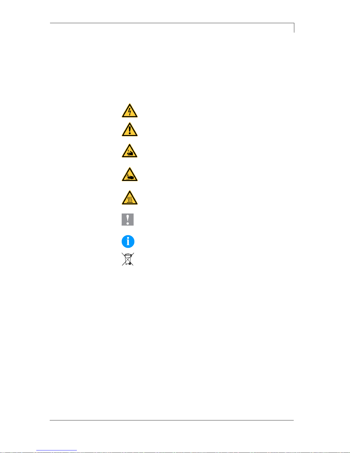
Basic information and warning references with the corresponding
signal words for the danger level are as follows specified in this
manual:
DANGER identifies an extraordinarily great and immediate
danger which could lead to serious injury or even death.
WARNING identifies a possible danger would could lead
to serious bodily injury or even death if sufficient
precautions are not taken.
WARNING of cutting injuries.
Pay attention that cutting injuries caused by blades, cutting
devices or sharp-edged parts are avoided.
WARNING of hand injuries.
Pay attention that hand injuries caused by closing
mechanical parts of a machine/equipment are avoided.
WARNING of hot surfaces.
Pay attention so as not to come into contact with hot
surfaces.
CAUTION indicates a potentially dangerous situation
which could lead to moderate or light bodily injury or
damage to property.
NOTICE gives you tips. They make a working sequence
easier or draw attention to important working processes.
Gives you tips on protecting the environment.
Handling instruction
Optional accessories, special fittings
Datum
Information in the display
1.2 Intended Use
The direct print module is a state-of-the-art device which complies
with the recognized safety-related rules and regulations. Despite this,
a danger to life and limb of the user or third parties could arise and the
direct print module or other property could be damaged while
operating the device.
The direct print module may only be used while in proper working
order and for the intended purpose. Users must be safe, aware of
potential dangers and must comply with the operating instructions.
Faults, in particular those which affect safety, must be remedied
immediately.

Introduction
DPM III xi series
6
Operating manual
04.18
The direct print module is solely intended to print suitable media which
have been approved by the manufacturer. Any other or additional use
is not intended. The manufacturer/supplier is not liable for damage
resulting from misuse. Any misuse is at your own risk.
Intended used includes heeding the operating manual, including the
maintenance recommendations/regulations specified by the
manufacturer.
NOTICE!
The complete documentation is included in the scope of
delivery on CD ROM and can also currently be found in the
internet.
1.3 Safety Instructions
The direct print module is designed for power supply systems of
230 V. Connect the direct print module only to electrical outlets with a
ground contact.
NOTICE!
When changing the mains voltage the fuse value is to adapt
accordingly (see Technical Data).
Couple the direct print module to devices using extra low voltage only.
Before making or undoing connections, switch off all devices involved
(computer, printer, accessories etc.).
Operate the direct print module in a dry environment only and do not
get it wet (sprayed water, mist etc.).
Do not operate the direct print module in explosive atmosphere and
not in proximity of high voltage power lines.
Operate the direct print module only in an environment protected
against abrasive dust, swarf and other similar impurity.
In case of cleaning and maintenance with an open cover, ensure that
clothing, hair, jewellery and similar personal items do not contact the
exposed rotating parts.
NOTICE!
With the open printing unit (due to construction) the requirements
of EN60950-1 regarding fire protection casing are not fulfilled.
These must be ensured by the installation into the end device.
The print unit can get hot during printing. Do not touch the printhead
during operation. Cool down the print unit before changing material,
removal or adjustment.
Carry out only the actions described in these operating instructions.
Any work beyond this may only be performed by the manufacturer or
upon agreement with the manufacturer.
Unauthorized interference with electronic modules or their software
can cause malfunctions.

DPM III xi series
Introduction
04.18
Operating manual
7
Other unauthorized work or modifications to the direct print module
can endanger operational safety.
Always have service work done in a qualified workshop, where the
personnel have the technical knowledge and tools required to do the
necessary work.
There are warning stickers on the direct print modules that draw your
attention to dangers. Therefore the warning stickers are not to be
removed as then you and others cannot be aware of dangers and may
be injured.
The direct printing unit must be integrated with the Emergency Stop
circuit when it is incorporated into the overall machine.
All isolating safety equipment must be installed before starting-up the
machine.
DANGER!
Danger to life and limb from power supply!
Do not open the casing.
CAUTION!
Two-pole fuse.
Before opening the housing cover, disconnect the
device from the mains supply and wait approx. 2 - 3
minutes until the power supply unit has discharged.

DPM III xi series
Machine Overview
04.18
Operating manual
9
2 Machine Overview
The direct print module is equipped with 8 vector, 6 bitmap and 6
proportional fonts. It is possible to print inverse, in italic format or 90
degrees turned fonts.
The handling of our durable print module is easy and comfortable. The
settings are made with the keys of the foil keyboard. At each time the
two-line display shows the current status.
An enormously high print quality is obtained by most modern
printhead technology.
Time-saving update of the design software is possible by interface.
As default, the print module is equipped with a parallel, serial and
USB interface. Additionally the IP version is by default equipped with
Ethernet interface. The device automatically recognizes by which
interface it is controlled.
Thanks to the large number of options the print module can be
adapted to each task.
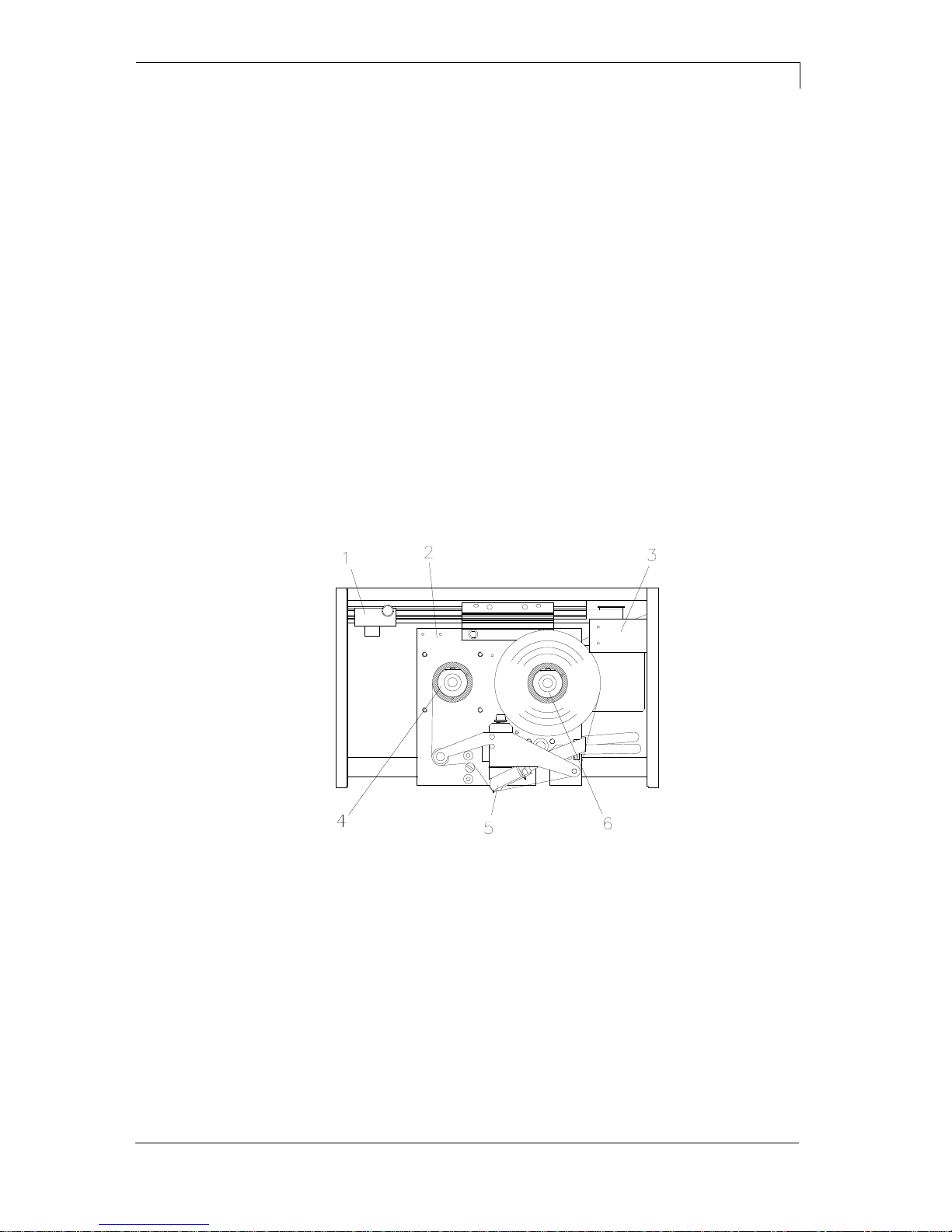
2.1 Print Mechanics
Figure 1
1 =
Zero point adjustment
2 =
Printing carriage
3 =
End position control
4 =
Ribbon rewinding unit
5 =
Printhead
6 =
Ribbon unwinding unit
Machine Overview
DPM III xi series
10
Operating manual
04.18
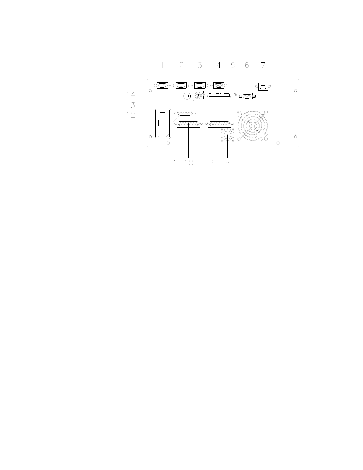
2.2 Connector Assignment of Control Unit
Figure 2
1 =
External output 1-4 (Output I)
2 =
External input 1-4 (Input I)
3 =
External output 5-8 (Output II)
4 =
Standard
Option
SUB-D plug 15-pin
External bushing I/O-24
see chapter 4.1
SUB-D plug 9-pin
External input 5-8
see chapter 4.1
5 =
Centronics interface
6 =
RS-232 interface
7 =
Ethernet interface (option)
8 =
Connecting cable power
9 =
Connecting cable motor
10 =
Connecting cable signal
11 =
Connecting cable sensors
12 =
Power supply
13 =
PS/2 keyboard connection
14 =
USB interface

DPM III xi series
Machine Overview
04.18
Operating manual
11
2.3 Connector Assignment of Control Unit IP Version
Figure 3
1 =
External output 1-4 (Output I)
2 =
External input 1-4 (Input I)
3 =
External output 5-8 (Output II)
4 =
External bushing I/O-24
5 =
RS-232 interface
6 =
Ethernet interface
7 =
Centronics interface
8 =
USB interface
9 =
Connecting cable sensors
10 =
Connecting cable power
11 =
Connecting cable signal
12 =
Connecting cable motor
13 =
Power switch
14 =
Electric supply

Machine Overview
DPM III xi series
12
Operating manual
04.18
2.4 Print Principle
Figure 4
After starting a print order the printhead moves against the print
medium. Afterwards the printing carriage moves corresponding to the
set or transferred layout length linear over the material which is to be
printed. After the print procedure the printhead again lifts up and the
printing carriage moves again to the starting position.

DPM III xi series
Operating Conditions
04.18
Operating manual
13
3 Operating Conditions
Before initial operation and during operation these operating
conditions have to be observed to guarantee save and interferencefree service of our direct print modules.
Therefore please carefully read these operating conditions.
Shipment and storage of our direct print modules are only allowed in
original packing.
Installation and initial operation of direct print modules is only allowed
if operating conditions were fulfilled.
Commissioning is prohibited until it can be established that, where
relevant, the machine into which the partly completed machinery is to
be incorporated complies with the provisions of Machinery Directive
2006/42/EC.
Initial operation, programming, operation, cleaning and service of our
direct print modules are only recommended after careful study of our
manuals.
Operation of direct print modules is only allowed by especially trained
persons.
NOTICE!
Perform trainings regularly. Content of the training are chapter
Operating Conditions, Loading Transfer Ribbon and chapter
Maintenance and Cleaning.
These indications are also valid for someone else's equipment
supplied by us.
Only use original spare and exchange parts.
Please contact the manufacturer with respect to spare/wear parts.
The installation place of direct print module should be even, free of
vibration and currents of air are to be avoided.
The direct print modules have to be installed to ensure optimal
operation and servicing.
The installation of the power supply to connect our direct print
modules has to be effected according to the international rules and
regulations, especially the recommendations of one of the three
following commissions:
International Electronic Commission (IEC)
European Committee for Electro technical Standardisation
(CENELEC)
Verband Deutscher Elektrotechniker (VDE)
Our direct print modules are constructed according to VDE and have
to be connected to a grounded conductor. The power supply has to be
equipped with a grounded conductor to eliminate internal interfering
voltage.
Conditions for
installation place
Installation of
power supply

Operating Conditions
DPM III xi series
14
Operating manual
04.18
Power line voltage and power line frequency: See type plate
Allowable tolerance of power line voltage:
+6% …−10% of nominal value
Allowable tolerance of power line frequency:
+2% …−2% of nominal value
Allowable distortion factor of power line voltage: <=5%
In case your net is infected (e.g. by using thyristor controlled
machines) anti-interference measures have to be taken. It is possible
to use one of the following possibilities:
Provide separate power supply to our direct print modules.
In case of problems please connect capacity-decoupled isolation
transformer or similar interference suppressor in front of our direct
print modules.
Emitted interference according to EN 55022
Interference voltage to wires according to EN 55022:2011-04
Interference field power according to EN 55022:2011-04
System perturbation according to EN 61000-3-2:2010-03
Flicker according to EN 61000-3-3:2014-03
Immunity according to EN 61000-6-2:2011-06
Stray radiation against discharge of static electricity according to
EN 61000-4-2:2009-12
Electromagnetic fields according to EN 61000-4-3:2011-04
Fast transient burst according to EN 61000-4-4:2013-04
Surge according to EN 61000-4-5:2007-06
High-frequency tension according to EN 61000-4-6:2009-12
Voltage interruption and voltage drop according to EN 61000-4-
11:2005-02
NOTICE!
This is a machine of type A. This machine can cause
interferences in residential areas; in this case it can be
required from operator to accomplish appropriate measures
and be responsible for it.
EN 60950-1: 2006 - Safety of pachaging machines
EN 60204-1: 2006 - Safety of machinery - Electrical equipment of
machines - Part 1
Technical data of
power supply
Anti-interference
measures
Stray radiation and
immunity from
disturbance
Machine safety

DPM III xi series
Operating Conditions
04.18
Operating manual
15
All connecting lines have to be guided in shielded lines. Shielding has
to be connected on both sides to the corner shell.
It is not allowed to guide lines parallel to power lines. If a parallel
guiding cannot be avoided a distance of at least 0.5 m has to be
observed.
Temperature of lines between: −15 …+80 °C.
It is only allowed to connect devices which fulfil the request 'Safety
Extra Low Voltage' (SELV). These are generally devices which are
checked corresponding to EN 60950.
The data cables must be completely protected and provide with metal
or metallised connector housings. Shielded cables and connectors are
necessary, in order to avoid radiant emittance and receipt of electrical
disturbances.
Allowable lines
Shielded line:
4 x 2 x 0,14 mm² ( 4 x 2 x AWG 26)
6 x 2 x 0,14 mm² ( 6 x 2 x AWG 26)
12 x 2 x 0,14 mm² (12 x 2 x AWG 26)
Sending and receiving lines have to be twisted in pairs.
Maximum cable length:
interface V 24 (RS-232C) - 3 m (with shielding)
USB - 3 m
Ethernet - 100 m
To avoid inadmissible heating, free air convection has to be ensured.
DPM IIIxi: Protection according IP 20
DPM III xi IP: Protection according IP 65
Ambient temperature °C (operation): Min. +5 Max. +40
Ambient temperature °C (transport, storage): Min. −25 Max. +60
Relative air humidity % (operation): Max. 80
Relative air humidity % (transport, storage): Max. 80
(bedewing of direct print modules not allowed)
Connecting lines to
external machines
Installation of
data lines
Air convection
Limit values

Operating Conditions
DPM III xi series
16
Operating manual
04.18
We do not take any responsibility for damage caused by:
Ignoring our operating conditions and operating manual.
Incorrect electric installation of environment.
Building alterations of our direct print modules.
Incorrect programming and operation.
Not performed data protection.
Using of not original spare parts and accessories.
Natural wear and tear.
When (re)installing or programming our direct print modules please
control the new settings by test running and test printing. Herewith you
avoid faulty results, reports and evaluation.
Only specially trained staff is allowed to operate the direct print
modules.
Control the correct handling of our products and repeat training.
We do not guarantee that all features described in this manual exist in
all models. Caused by our efforts to continue further development and
improvement, technical data might change without notice.
By further developments or regulations of the country illustrations and
examples shown in the manual can be different from the delivered
model.
Please pay attention to the information about admissible print media
and the notes to the direct print module maintenance, in order to avoid
damages or premature wear.
We endeavoured to write this manual in an understandable form to
give and you as much as possible information. If you have any queries
or if you discover errors, please inform us to give us the possibility to
correct and improve our manual.
Guarantee
DPM III xi series
Technical Data
04.18
Operating manual
17
4 Technical Data
DPM III xi53
DPM III xi107
DPM III xi128
Print width
53,3 mm
106,6 mm
128 mm
Print length
60 mm, 140 mm, 240 mm, 340 mm, 447 mm, 570 mm, 630 mm
Resolution
300 dpi
Print speed
50…450 mm/s*
50…450 mm/s*
50…400 mm/s*
Back speed
50…500 mm/s*
50…500 mm/s*
50…400 mm/s*
Printhead
Corner Type
Built-in fonts
vector fonts: 8
bitmap fonts: 6
proportional fonts: 6
font height: min. 1 mm - max. 99 mm
Bar codes
1D bar codes
CODABAR, Code 128, Code 2/5 interleaved, Code 39, Code 39 extended,
Code 93, EAN 13, EAN 8, EAN ADD ON, GS1-128, Identcode, ITF 14,
Leitcode, Pharmacode, PZN Code, UPC-A, UPC-E
2D bar codes
CODABLOCK F, DataMatrix, GS1 DataMatrix, MAXICODE,
PDF 417, QR Code
Composite bar codes
GS1 DataBar Expanded, GS1 DataBar Limited, GS1 DataBar Omnidirectional,
GS1 DataBar Stacked, GS1 DataBar Stacked Omnidirectional, GS1 DataBar
Truncated
Interface
Serial: RS-232C (up to 19200 Baud); Parallel: Centronics; USB: 1.1
Ethernet: 10/100 Base-T**
Transfer ribbon
Core diameter
Length max.
Width max.
Colour
25,4 mm / 1"
450 m (Ø 85 mm)
55 mm
outside/inside
25,4 mm / 1"
450 m (Ø 85 mm)
110 mm
outside/inside
25,4 mm / 1"
450 m (Ø 85 mm)
130 mm
outside/inside
Module memory
Memory card
max. 4 MB
Compact Flash Card: 1 GB, 2 GB
Dimensions in mm (width x height x depth)
Print mechanics
(print length + 230) x
170 x 260
(print length + 230) x
170 x 3150
(print length + 230) x
x 170 x 335
Control unit
285 x 130 x 350 - connecting cable to mechanics 2,5 m
Weight
Print mechanics
Electronics (incl. cable)
(depending on print width)
e.g. xi53 x 60 mm = 7,3 kg / xi128 x 630 mm = 23 kg
10,5 kg
Connection values
Pneumatic connection
Air consumption typical*
* hub 1,5 mm
150 cycle/minute
6 bar operating pressure
Nominal voltage
Nominal current
Safety values
min. 6 bar dry and free of oil
DPM IIIxi 53: 150 ml/min – DPM IIIxi 107+128: 300 ml/min
standard: 230 V / 50-60 Hz
option: 115 V / 50-60 Hz
230 V / 1,5 A − 115 V / 3 A
230 V / 3,15 AT − 115 V / 6,3 A
Operation data
Ingress Protection Rating
Temperature
Relative humidity
IP 65 (IP version only)
5-40 °C
max. 80% (non-condensing)
Technical modifications are subject to change.
*
depending on installation position
**
for DPM IIIxi optional only
Technical Data
DPM III xi series
18
Operating manual
04.18
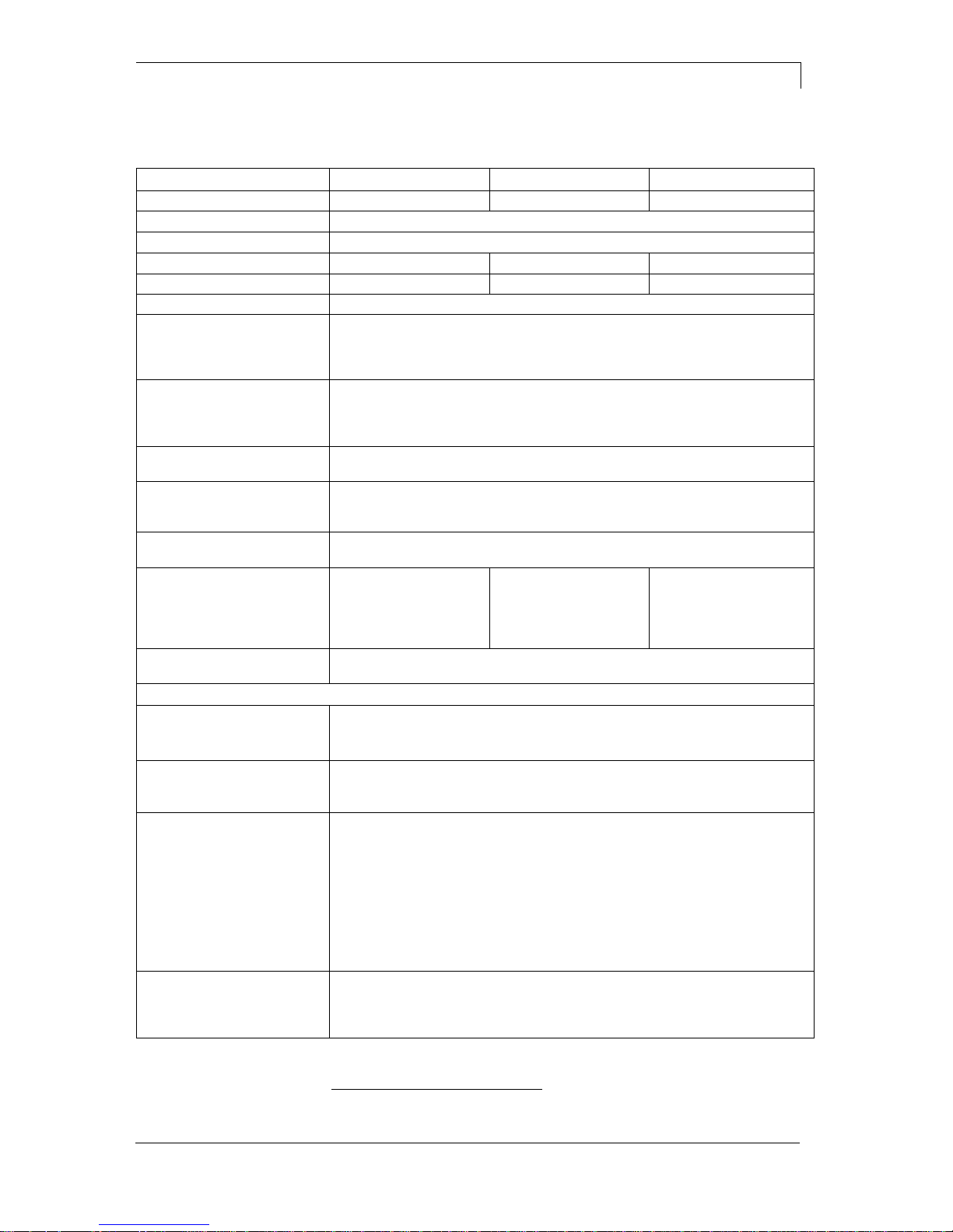
4.1 Control Inputs and Outputs (Standard)
Figure 5
A = External output 1-4 (Output I)
B = External input 1-4 (Input I)
C = External output 5-8 (Output II)
D = External bushing 15pin (I/O-24)
By means of the signal outputs different operating states of the print
module can be queried.
The signal outputs are provided by two 9-pin SUB-D-bushings
(OUTPUT I and OUTPUT II) on the back side of the control unit.
They consist of optocoupler semiconductor sections, which are
connected through and/or blocked according to different operating
states.
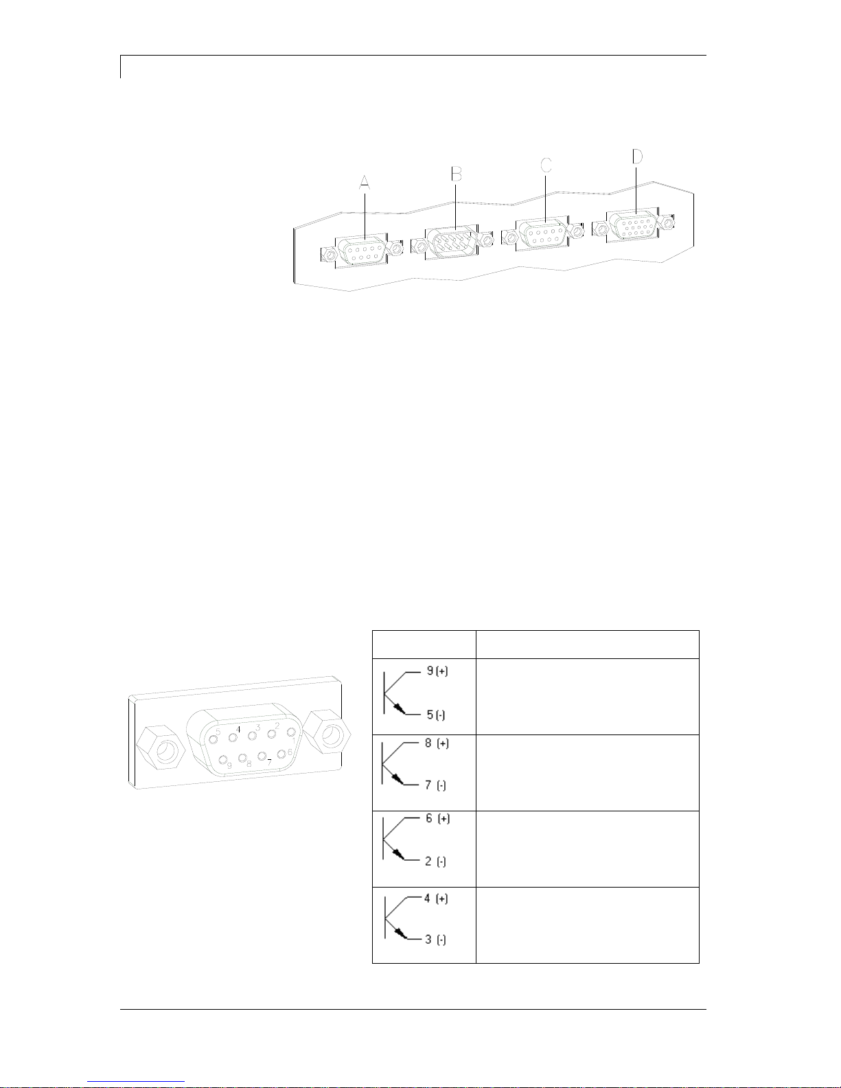
The maximum allowable current in a semiconductor section is
lmax = 30 mA.
Output I
Figure 5, A
Figure 6
PIN (bushing)
Output I
Out 1: Error message
Each error status such as ribbon
error is displayed.
Out 2: Print order
The print module was activated by a
print order.
Out 3: Generation
The print module is filled with current
layout data.
Out 4: Layout print
The content of print memory is
transferred on the printable medium
by means of the printhead.
Plug connection - back
side of control unit
Control outputs
DPM III xi series
Technical Data
04.18
Operating manual
19
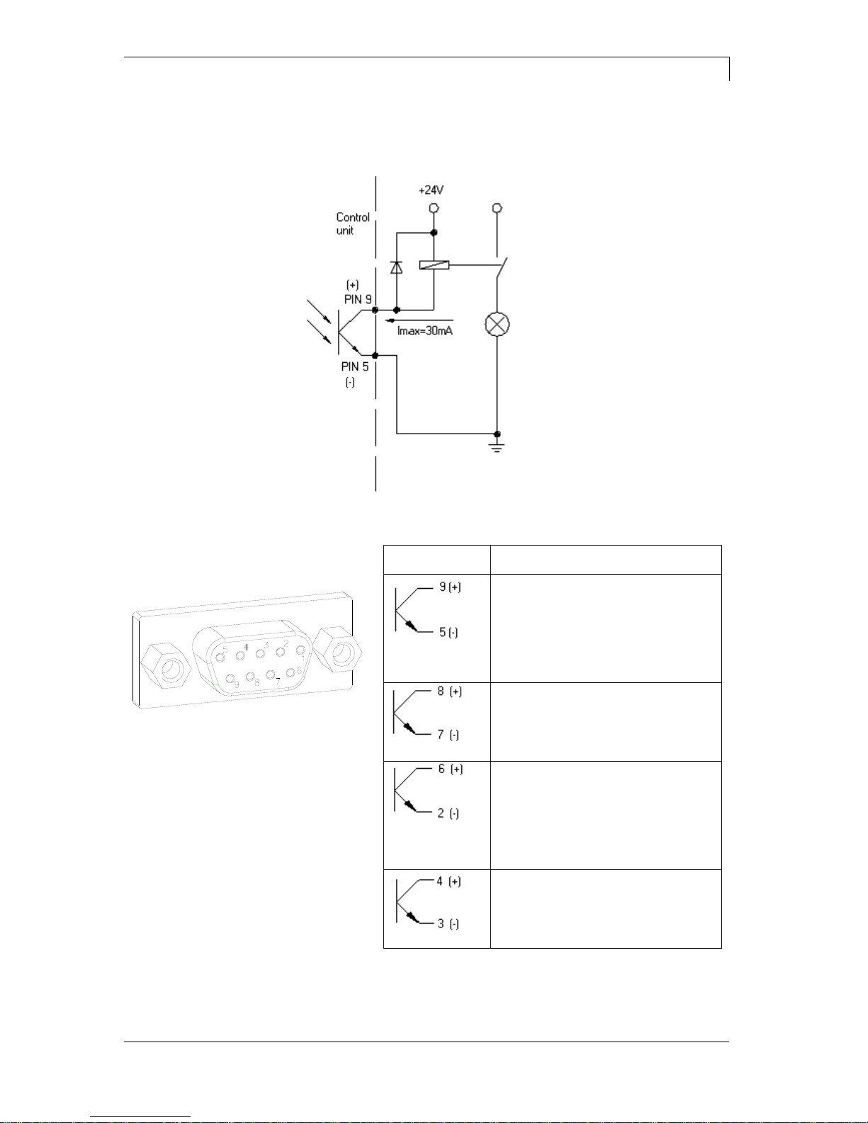
Connection of a lamp to a 24V relay by Out 1:
Figure 7
Output II
Figure 5, C
Figure 8
PIN (bushing)
Output II
Out 5: Print-Ready signal
It is indicated if the print module is
ready to process a start impulse. In
contrary to the print order signal, the
generating time is taken into
consideration.
Out 6: Printhead up
The printhead has reached the upper
rest position (e.g. return to zero
point).
Out 7: Return to start
After termination of print procedure
the flexible part of the print module is
moved back to the start position.
After the start position was reached a
new start can be released.
Out 8: Prior warning of transfer
ribbon end
Example
Technical Data
DPM III xi series
20
Operating manual
04.18
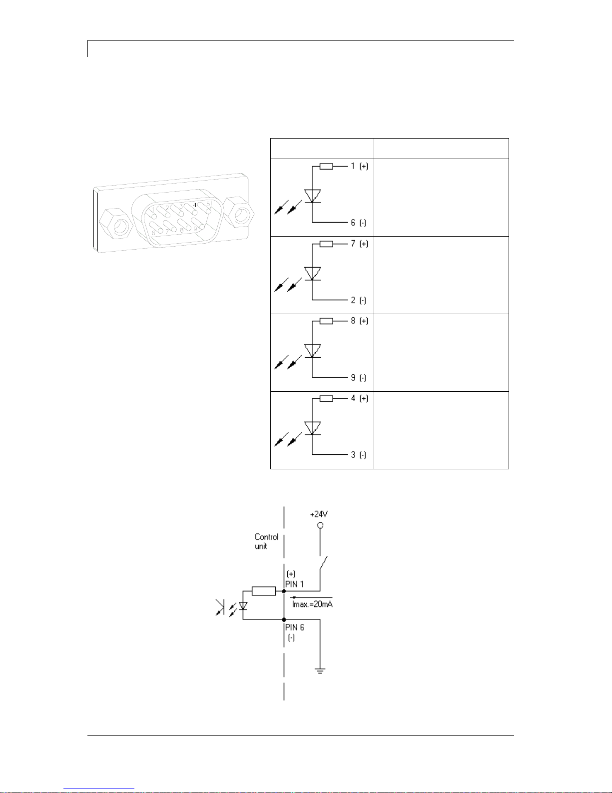
By means of the control inputs it is possible to control printing. The
control inputs at Input I are galvanic separated and have to be
provided with an external tension source. The signal level is active
"HIGH".
Input I
Figure 5, B
Figure 9
PIN (pin)
Input I
In 1: Print start
In 2: Not used
In 3: Reset external counter
In 4: Not used
Connection of a switch with 24V voltage supply by In 1:
Figure 10
Control inputs
Example
DPM III xi series
Technical Data
04.18
Operating manual
21
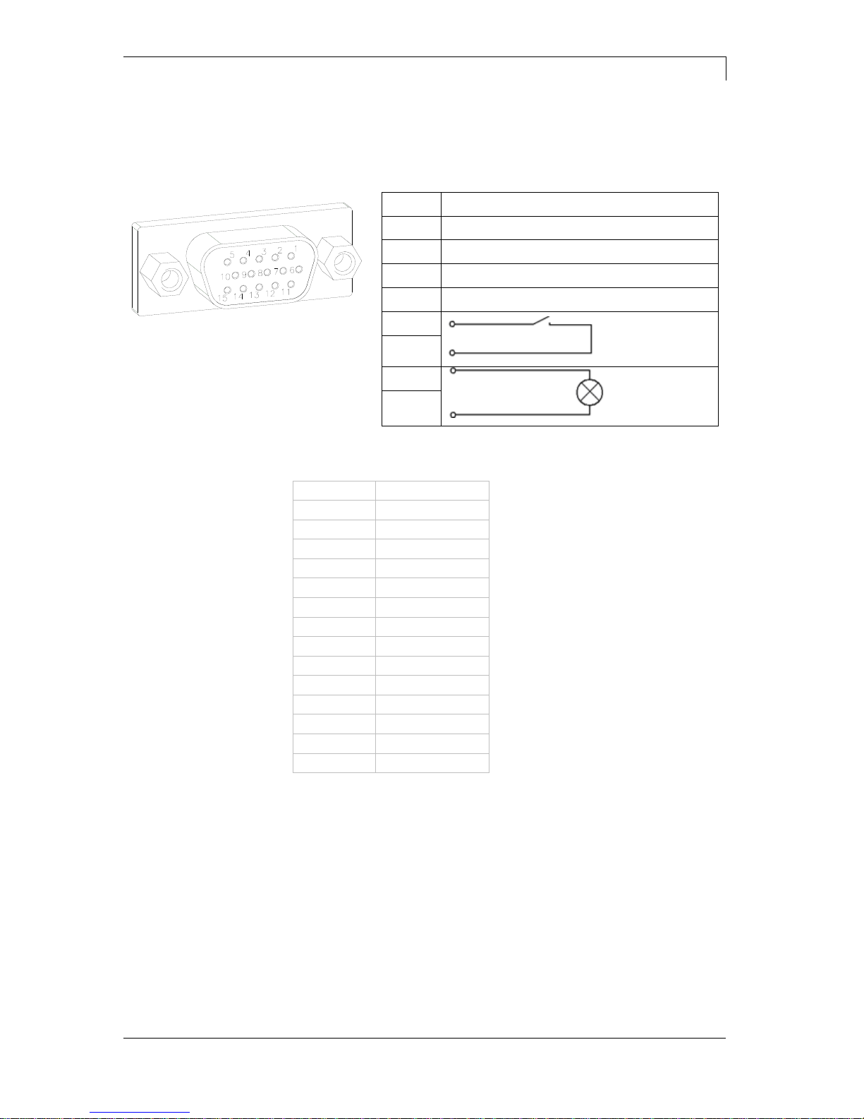
External bushing I/O-24
Figure 5, D
This input is executed as 15-pole and provides usersided 24V/100mA.
In case of using this bushing, exists no galvanic
separation.
Figure 11
PIN
Function
1, 6
Gnd
5, 10
24 V / 100 mA
3
Print start (NPN initiator)
2
Print start (PNP initiator)
4
Print start by
potential-free
contact
14
7
Signal lamp
24 V / 100 mA
(error)
13
PIN 1
white
PIN 2
brown
PIN 3
green
PIN 4
yellow
PIN 5
grey
PIN 6
pink
PIN 7
blue
PIN 8
red
PIN 9
black
PIN 10
purple
PIN 11
grey-pink
PIN 12
red-blue
PIN 13
white-green
PIN 14
brown-green
PIN 15
free
Pin assignment
Technical Data
DPM III xi series
22
Operating manual
04.18
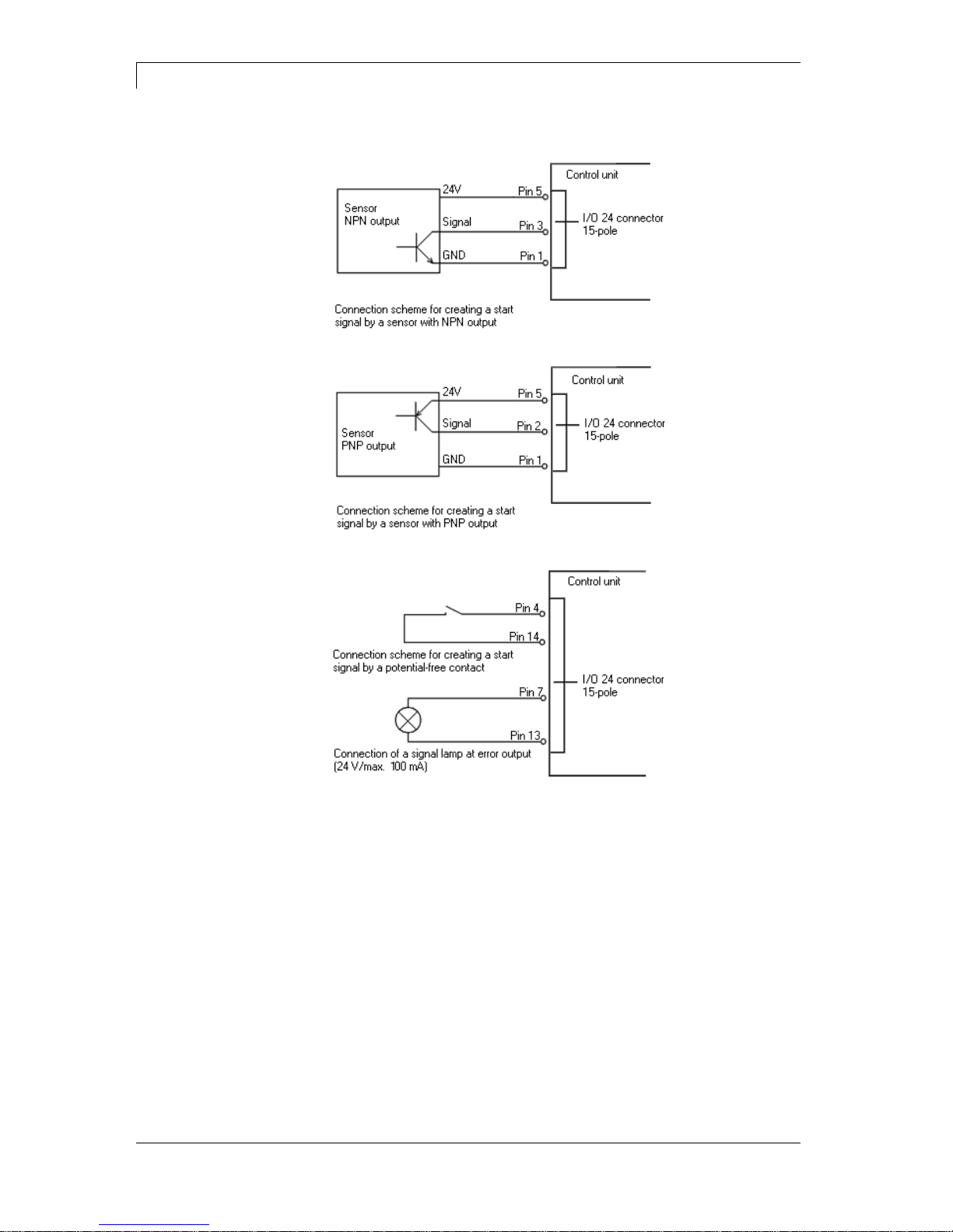
Example 1
Example 2
Example 3
DPM III xi series
Technical Data
04.18
Operating manual
23
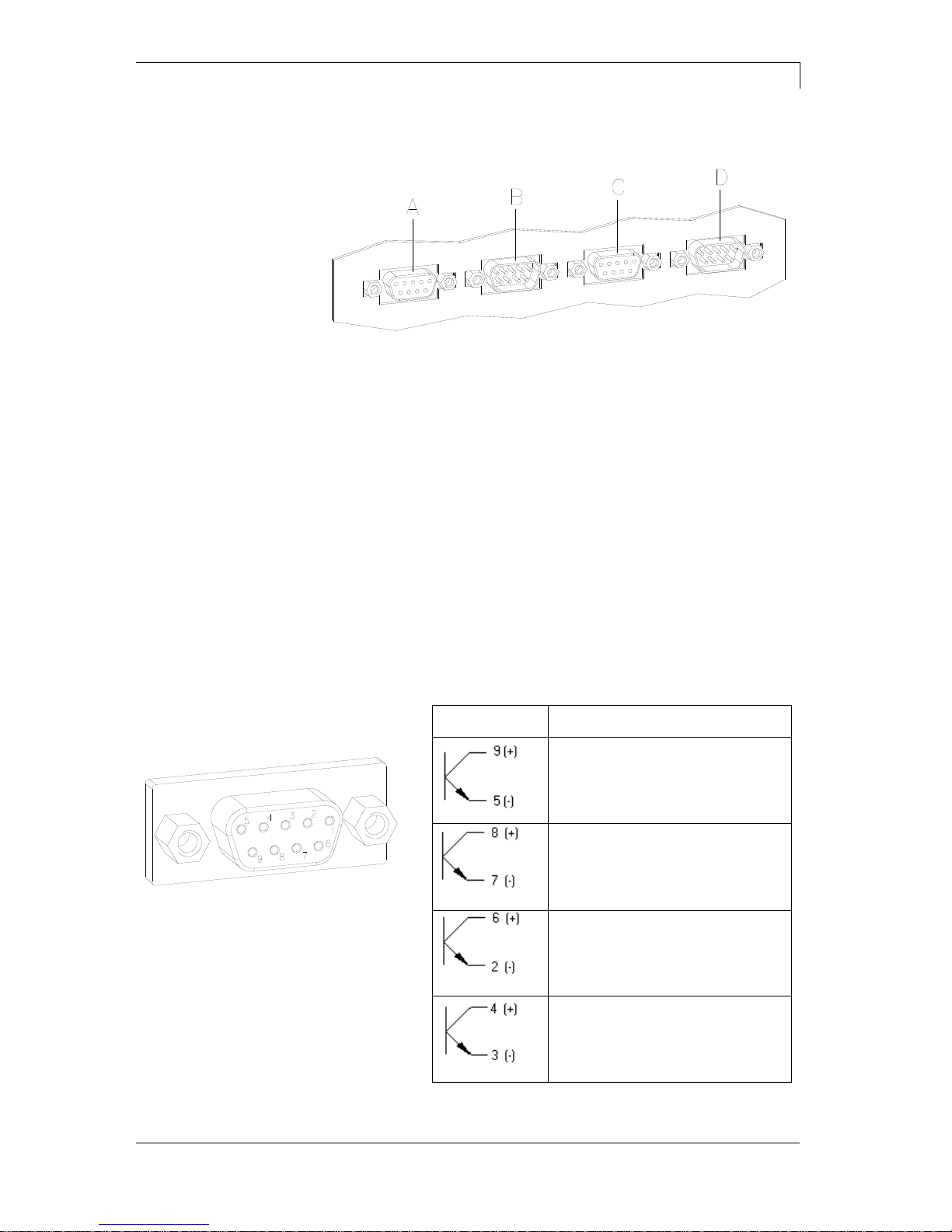
4.2 Control Inputs and Outputs (Option)
Figure 12
A = External output 1-4 (Output I)
B = External input 1-4 (Input I)
C = External output 5-8 (Output II)
D = External input 5-8 (Input II)
By means of the signal outputs different operating states of the print
module can be queried.
The signal outputs are provided by two 9-pin SUB-D-bushings
(OUTPUT I and OUTPUT II) on the back side of the control unit.
They consist of optocoupler semiconductor sections, which are
connected through and/or blocked according to different operating
states.
The maximum allowable current in a semiconductor section is
lmax = 30 mA.
Output I
Figure 12, A
Figure 13
PIN (bushing)
Output I
Out 1: Error message
Each error status such as ribbon
error is displayed.
Out 2: Print order
The print module was activated by
a print order.
Out 3: Generation
The print module is filled with
current layout data.
Out 4: Layout print
The content of print memory is
transferred on the printable medium
by means of the printhead.
Plug connection - back
side of control unit
Control outputs

Technical Data
DPM III xi series
24
Operating manual
04.18
Connection of a lamp to a 24V relay by Out 1:
Figure 14
Output II
Figure 12, C
Figure 15
PIN (bushing)
Output II
Out 5: Print-Ready signal
It is indicated if the print module is
ready to process a start impulse. In
contrary to the print order signal, the
generating time is taken into
consideration.
Out 6: Printhead up
The printhead has reached the upper
rest position (e.g. return to zero
point).
Out 7: Return to start
After termination of print procedure
the flexible part of the print module is
moved back to the start position.
After the start position was reached a
new start can be released.
Out 8: Prior warning of transfer
ribbon end
Example

DPM III xi series
Technical Data
04.18
Operating manual
25
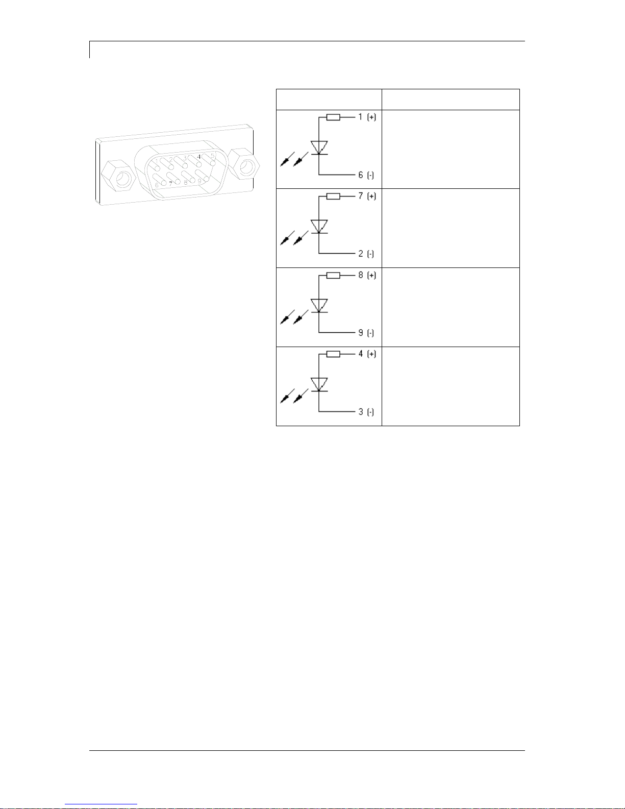
By means of the control inputs it is possible to control printing. The
control inputs at Input I are electroplated separated and have to be
provided with an external tension source. The signal level is active
"HIGH".
Input I
Figure 12, B
Figure 16
PIN (pin)
Input I
In 1: Print start
In 2: Not used
In 3: Reset external counter
In 4: Not used
Connection of a switch with 24V voltage supply by In 1:
Figure 17
Control inputs
Example
Technical Data
DPM III xi series
26
Operating manual
04.18
Input II
Figure 12, D
Figure 18
PIN (pin)
Input II
In 5: Not used
In 6: Not used
In 7: Not used
In 8: Not used

DPM III xi series
Installation and Initiation
04.18
Operating manual
27
5 Installation and Initiation
Lift the direct print module out of the box.
Check the direct print module for transport damages.
Check delivery for completeness.
Print mechanics.
Control unit.
Power cable.
Connection cable (printhead/motors, sensors, power).
Mini controller.
Manometer.
Pneumatic tube.
Push-on connector.
I/O accessories (female connectors for I/O, I/O 24 cable).
1 transfer ribbon roll.
Empty core, mounted on transfer ribbon rewinder.
Cleaning foil for printhead.
Documentation.
CD with printer drivers.
NOTICE!
Retain original packaging for subsequent transport.
Unpack the direct print
module
Scope of delivery
Installation and Initiation
DPM III xi series
28
Operating manual
04.18
5.1 Installation of Print Mechanics at Machines
NOTICE!
With the open printing unit (due to construction) the requirements
of EN60950-1 regarding fire protection casing are not fulfilled.
These must be ensured by the installation into the end device.
On the side parts of the print mechanics there are two M6 threads on
the upper side and the back side to be used for fasten the print
mechanics.
Please observe the following conditions:
The maximum thread engagement of the M6 threads is 14 mm.
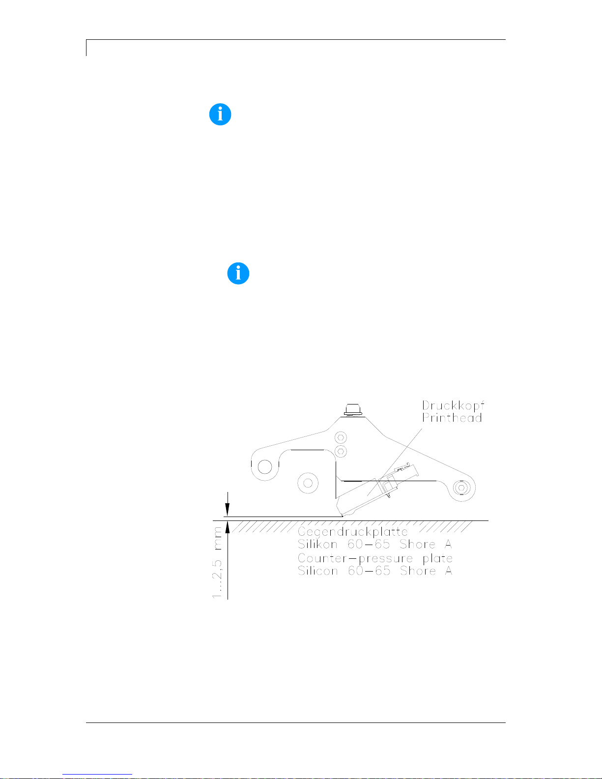
The print mechanics has to be installed with a distance from
printhead to brake stator of 1…2,5 mm (see illustration).
NOTICE!
A distance of 2 mm is recommended.
The best print results can be received if the silicon of printing roll
consists of a hardness of 60…65° Shore A (average value of
roughness Ra 3.2 µm).
The print surface has to be installed parallel to the linear
movement of print unit and the focal line of printhead.
Discrepancies to the focal line and cavities in the print surface of
0.2 mm can lead to an inferior print quality at these positions.
Figure 19
DPM III xi series
Installation and Initiation
04.18
Operating manual
29
5.2 Connection of Pneumatic Power Supply
The pneumatic power supply for the printhead mechanics has to be
made available a minimum continuous pressure of 4…6 bars in front
of the pressure regulator. The maximum pressure in front of the
pressure regulator is 7 bars and 4 bars after the pressure regulator.
NOTICE!
A pneumatic power supply of 4 bars is recommended.
The compressed-air has to be dry and oil free.
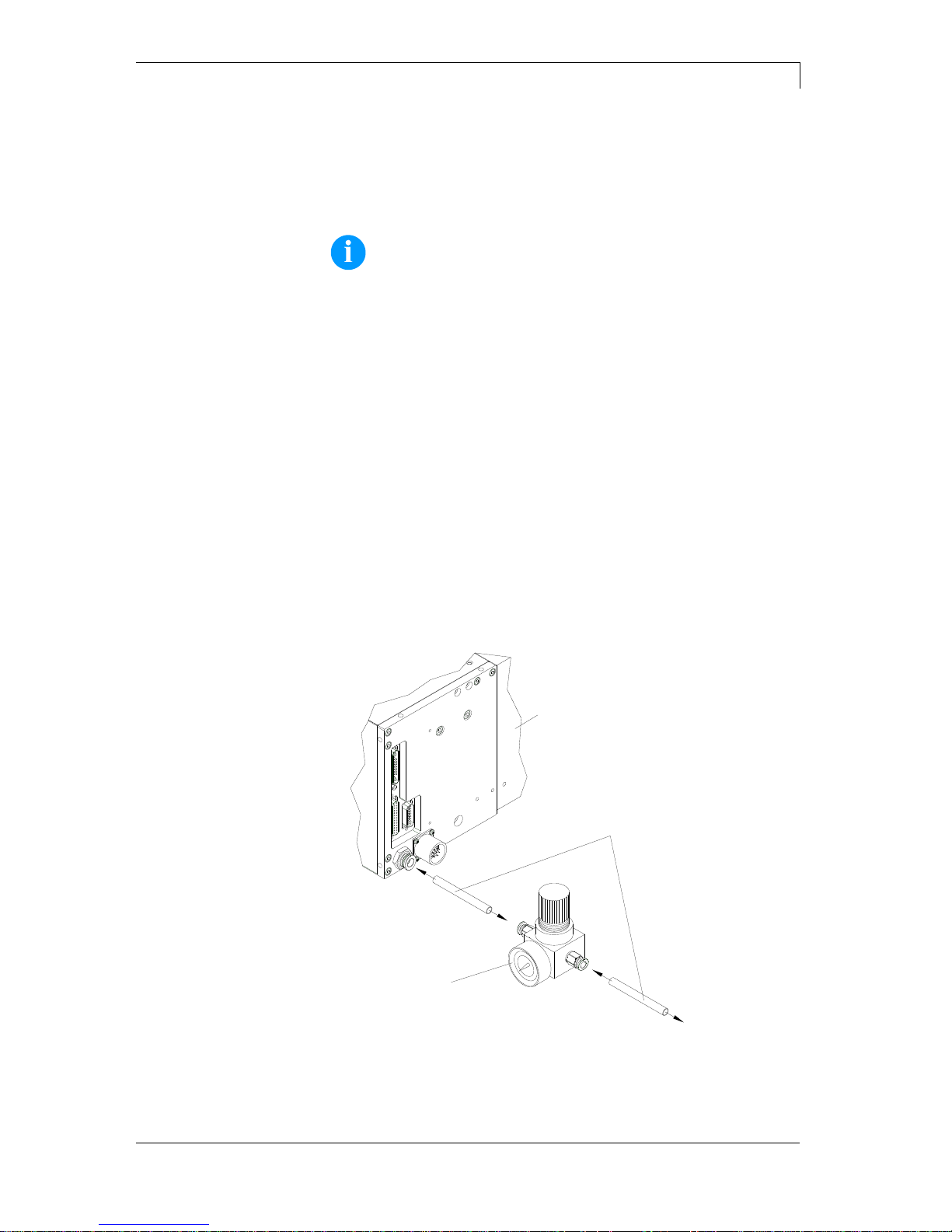
The supplied pressure regulator with manometer is to connect with a
pneumatic tube Ø 8 mm via a plugging bolting to the pneumatic power
supply. It is necessary to make a connection between the pressure
regulator and the print mechanics via a pneumatic tube Ø 8 mm.
Please observe the following notes:
Position pressure regulator as near as possible to the print
mechanics.
The pressure regulator is only to operate in the direction that is
indicated on its underside. The direction shows the way of the
streaming air.
It is not allowed to bend the pneumatic tubes.
Shortening of the pneumatic tubes has to be made with a clean
right-angled cut without squashing the tube. If necessary use
special tools (available in pneumatic requirements).
Please observe a possible short length of the 8 mm pneumatic
tubes.
Druckmechanik
Druckluftversorgung
Pneumatikschlauch
min. 4 bar, max. 7 bar
Druckregler mit Manometer
Print mechanics
Pneumatic power supply
Pneumatic tube 8x1
Pressure regulator with manometer
Figure 20

Installation and Initiation
DPM III xi series
30
Operating manual
04.18
5.3 Adjustment of Pressure Power
Pressure power in dependence
of air pressure i53
(one pressure cylinder)
0
1
2
3
4
5
2 3 4 5
Air press ure in bar
Pressure in kg
Lift 1 mm Lift 2 mm Lift 3 mm
Pressure power in dependence
of air pressure i107
(two pressure cylinder)
0
1
2
3
4
5
6
7
8
2 3 4 5
Air press ure in bar
Pressure in kg
Lift 1 mm Lift 2 mm Lift 3 mm
Pressure power in dependence
of air pressure i128
(two pressure cylinders)
0
1
2
3
4
5
6
7
8
2 3 4 5
Air press ure in bar
Pressure in kg
Lift 1 mm Lift 2 mm Lift 3 mm
The pressure power of the printhead can be set with the pressure
regulator. The values are indicated in the following table:
NOTICE!
If the pressure power is set too low then the printhead has no
more contact to the counter-pressure plate. This damages the
printhead due to the missing heat dissipation during the
printout. In case of too low pressure an error message
appears. This error message is to protect the printhead for
overheating only and is not to use as print quality control (the
control suffers with too low pressure, too).
The lift indicates the distance between printhead and brake stator in
'print less' status.
DPM III xi53
DPM III xi107
DPM III xi128
Recommended pressure
power:
30 N
40 N
40 N
Max. pressure power:
36 N
48 N
48 N
As the mechanical wear and tear of the printhead increases with the
pressure power, the pressure power should be as low as possible.

DPM III xi series
Installation and Initiation
04.18
Operating manual
31
5.4 Connecting the Direct Print Module
The direct print module is equipped with a versatile power supply unit.
The device may be operated with a mains voltage of 230 V / 50…60
Hz without any adjustments or modifications.
CAUTION!
The direct print module can be damaged by undefined
switch-on currents.
Set de power switch to '0' before plugging in the direct
print module.
Insert power cable into power connection socket.
Insert plug of power cable into a grounded electrical outlet.
NOTICE!
Insufficient or missing grounding can cause faults during
operation.
Ensure that all computers and connection cables connected to
the direct print module are grounded.
Connect direct print module to computer or network with a
suitable cable.
5.5 Before Initial Operation
Mount print mechanics.
Connect all cables between print mechanics and control unit.
Protect cables against unintentional unscrewing.
Connect compressed air line.
Connect control unit and PC by printer interface.
Connect control unit and packaging machine by inputs and
outputs.
Connect power cable of control unit.
Connecting to the
power supply
Connecting to a
computer or to a
computer network

Installation and Initiation
DPM III xi series
32
Operating manual
04.18
5.6 Print Control
Because of the fact that the print module is always in control mode it
is only possible to transmit and not to start print orders by the
available interfaces (serial, parallel, USB or Ethernet). The print is
started by a start signal to the 'print start-control input'. It is necessary
for the control unit to recognise the moment of setting the start signal
and therefore it is possible and also necessary to observe the print
status by the outputs.
5.7 Initiation
Once all connections have been made:
Switch control unit on with the power switch.
After switching on the device the main menu appears which
shows the model type, current date and time.
Insert transfer ribbon (see chapter 5.8, on page 33).

DPM III xi series
Installation and Initiation
04.18
Operating manual
33
5.8 Loading Transfer Ribbon
NOTICE!
As for the electrostatic unloading the thin coating of the thermal
printhead or other electronic parts can be damaged, the
transfer ribbon should be antistatic.
The use of wrong materials can lead to printer malfunctions
and the guarantee can expire.
Figure 21
NOTICE!
Before loading a new transfer ribbon roll, we recommend to
clean the printhead with printhead and roll cleaner (97.20.002).
For detailed information, please see page 64.
The handling instructions for the use of Isopropanol (IPA) must
be observed. In the case of skin or eye contact, immediately
wash off the fluid thoroughly with running water. If the irritation
persists, consult a doctor. Ensure good ventilation.
Load a new transfer ribbon roll (1) onto the unwinding unit (2) and
push it until it stops.
NOTICE!
The colour of the transfer ribbon must be on the outside.
Load an empty rewinding roll (3) onto the rewinding unit (4) until it
stops.
Load the transfer ribbon according to the illustration.
Depending on the transfer ribbon, the 'alternative' ribbon guiding
can improve the print quality.
Stick the transfer ribbon with an adhesive tape to the empty roll
and tighten the transfer ribbon with some turns of the roll.

DPM III xi series
Foil Keyboard
04.18
Operating manual
35
6 Foil Keyboard
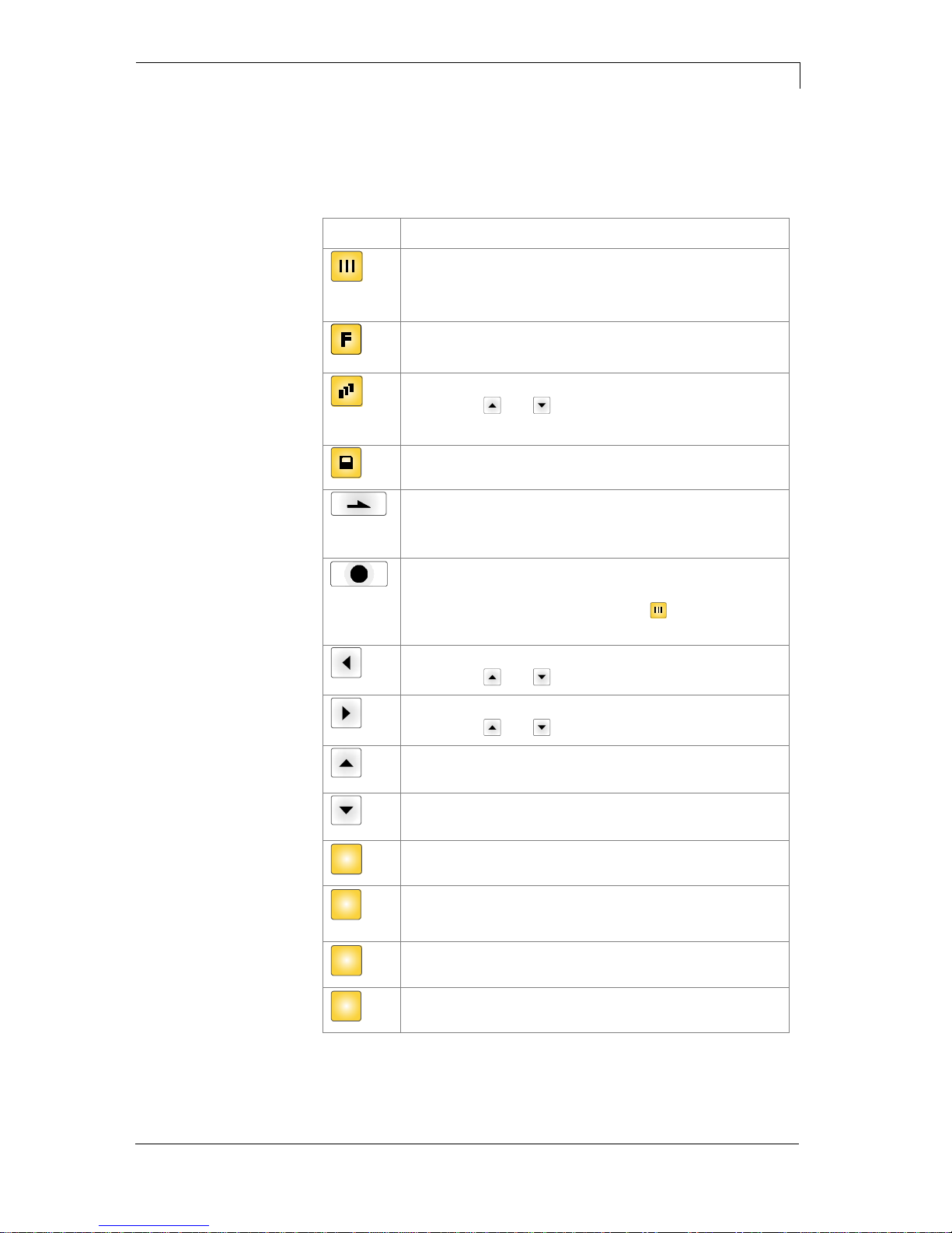
6.1 Keyboard Assignment (Standard)
Key
Function
Back to the main menu.
Start a test print.
Delete a stopped print order.
Change to the function menu.
In function menu: one menu item back.
Change to the quantity (number of pieces) menu.
Press keys and to select the number of layouts
that should be printed.
Change to the menu of the CF card.
In main menu: feed of one layout.
In function menu: skip to the next menu item.
In dispensing mode: release of start signal.
Confirm settings and modifications.
Stop and continue current print orders.
Delete a stopped print order with key . No further
layout of the print order is printed.
Return to the previous input field.
Press keys and to change the values.
Skip to the next input field.
Press keys and to change the values.
In function menu: increase figure at the cursor position.
In main menu: upwards movement of printhead.
In function menu: decrease figure at the cursor position.
In main menu: downwards movement of printhead.
C
Delete the complete input.
E
Confirm settings in the function menu.
After confirmation of settings, return to the main menu.
F1
Not yet in use.
F2
Not yet in use.

Foil Keyboard
DPM III xi series
36
Operating manual
04.18
6.2 Keyboard Assignment
(Text Entry/Customized/Memory Card)
The control unit of the print module is equipped with an alphanumeric
character block which allows the user to enter parameters and
customised variables without the connection of an external keyboard.
Each key contains letters and similar to the use of a mobile phone
(like sms) a direct and time-saving input is possible.
The mode is displayed in the first line at the right position so the user
can control in which input mode is selected.
As the input is almost done with characters from one mode, the
characters are divided in different groups. Following input modes are
available:
Symbol
Mode
0
Standard, starting with figures
M
Starting with capital letters
m
Starting with small letters
A
Input Alt
a
Input Alt, is switched off after one character
Mode 0
This mode is displayed as default. At first the figure which
corresponds to the key is displayed, then all capital and afterwards the
small letters.
Mode M
At first all capital, then the small letters and at last the corresponding
figure.
Mode m
At first all small letters, then the figure and at last the capital letters.
Mode A
This mode can be used for the creation of special characters. The
desired character can be displayed by the assigned number by
entering the ANSI code. Please note that the ANSI code has to
consist of three digits, i.e. you have possible to enter a zero first.
Mode a
Same as mode A. After input of the selected ANSI code the machine,
however, changes back to the previously selected input mode.

DPM III xi series
Foil Keyboard
04.18
Operating manual
37
Key
Function
Back to the main menu.
Start a test print.
Delete a stopped print order.
Not yet in use.
Delete the character at the cursor position.
If the cursor is between the last character then the last
character is deleted.
The characters are deleted only if they were entered via
the character block.
Select the entry mode.
Confirm the entry and change to the main menu.
Confirm and/or finish the entry.
Cursor moves one position to the left.
Cursor moves one position to the right.
Customized variables (user guiding): Change between
the individual entries.
Customized variables (user guiding): Change between
the individual entries.
C
Delete the complete input. The input is deleted only if
before entered by using the number block.
E
Confirm the settings in the function menu.
After confirmation of the settings, return to the main
menu.
F1
Not yet in use.
F2
Not yet in use.


DPM III xi series
Function Menu
04.18
Operating manual
39
7 Function Menu
7.1 Menu Structure
Speed / contrast
Transfer ribbon control
On weak, On strong sensibility, Off
X Offset
Print settings
Layouts / cycle
Ribbon speed
Service position
Brake / delay
Head delay
Backfeed delay
Machine parameters
Operating mode
Back speed
Print offset
Rotate layout
Alignment
Layout settings
Print length
Column printing
Flip layout
Material selection
Ribbon save
Ribbon save mode On/Off
Language (DE/GB/FR/ES/PT/NL/IT/DK/FI/PL)
Keyboard layout (DE/GB/FR/GR/ES/SE/US)
Customized entry
Hotstart
Password protection
Layout confirmation
Standard layout On/Off
Device settings
Field handling
Off, graphic received, delete graphic
Codpage
External parameters
Buzzer / display
Ready while printing
I/O parameters
IO protocol
Save signal
Debounce
Start signal delay
IN signal level
OUT signal level

Function Menu
DPM III xi series
40
Operating manual
04.18
Network (optional)
IP address
Net mask
Standard gateway
Speed / Duplex
DHCP
Printer name
Remote console
Port
Interval
Data memory
COM1 / Baud / Parity / Data bits / Stop Bits
SOH start sign, ETB end sign
Parallel port
Interface
Emulation
Emulation On/Off
Date & Time
Start of summertime (format)
Start of summertime (date)
Start of summertime (time)
End of summertime (format)
End of summertime (date)
End of summertime (time)
Time shifting
Set date/time
Summertime On/Off
Online / Offline
Ribbon prior warning/diameter
Service functions
Input / Output
START / END / TR / P / H
Paper counter
Heater resistance
Printhead temperature
Motor Ramp
Print examples
Format
Free memory
CompactFlash card
Load file
Save layout
Change directory
Delete file
Save configuration

DPM III xi series
Function Menu
04.18
Operating manual
41
7.2 Print Settings
Press key to access the function menu.
Press key to select the menu.
Speed:
Indication of speed in mm/s
(see Technical Data, on page 17).
Contrast:
Indication of contrast in %.
Value range: 10%…200 %.
Step size: 10%.
Press key to arrive at the next menu item.
Ribbon control:
Examination if the transfer ribbon roll is to end or if the ribbon was torn
at the unwinding roll.
Off: The ribbon control is deselected, i.e. the direct print module
continues without an error message.
On: The ribbon control is selected, i.e. the current print order is
interrupted and an Error Message appears at the display.
strong sensibility: The direct print module reacts immediately to the
end of the transfer ribbon.
weak sensibility: The direct print module reacts at approx. 1/3 more
slowly to the end of the transfer ribbon.
Press key to arrive at the next menu item.
X displacement:
Indication of displacement in X direction. The fields on the layout are
moved.
Value range: −90.0…+90.0.

Function Menu
DPM III xi series
42
Operating manual
04.18
7.3 Machine Parameters
Press key to access the function menu.
Press key as long as you arrive at the 'Machine Parameters'
menu.
Press key to select the menu.
Mode:
Selection of operating mode.
Mode 1 = Single item processing:
A print order with a defined number of pieces is transferred. After the
generating process the target number and the actual number of
pieces is shown in the display. A cycle is started via signal input 1 or
with key . With each cycle the actual number of pieces is
increased by the number of printed layouts. In case the target number
of pieces is reached the print order is finished and the display shows
again the main menu.
Mode 2 = Continuous mode:
A print order is transferred. After the generating process the number
of printed layouts is shown in the display. A cycle is started via signal
input 1 or with key . With each cycle the number of printed
layouts is increased. The print order is active as long as it is
terminated by the user or in case of new data transmission.
Mode 3:
Actually not used.
Mode 4 = Continuous mode, return without 'layout print' signal:
This operating mode corresponds to mode 2. At the return of the print
unit to the zero point of machine, however, the signal output 4 'layout
print' is not active.
Mode 5:
Actually not used.
Mode 6 = Test mode:
This operating mode corresponds to mode 2. After the return of the
print unit to the zero point of the machine, however, internally a further
cycle is started (endurance test).
Mode 7 = Direct start:
A print order is transferred. After termination of generating process the
print order is executed without an external signal.
Mode 8 = Single item processing, return without 'layout print'
signal:
This operating mode corresponds to mode 4 but not continuous.

DPM III xi series
Function Menu
04.18
Operating manual
43
Press key to arrive at the next menu item.
Back-Speed:
Indication of back speed of the print mechanics after print end in
mm/s.
Each cycle of the machine consists of printing and return to the zero
point of machine. It is possible to set the print speed and back speed
separately. The setting range for the back speed is between 50 and
500 mm/s.
Because of this value you can select for low machine clock cycles an
operating method which saves the material and increases in this way
the life of the printhead.
Because of the mass moment of inertia it could be better to reduce the
speed at an installation position of the print unit at >30° horizontal.
Value range: 50…500 mm/s.
Press key to arrive at the next menu item.
Print offset:
Indication of distance of the layout (res. the first layout in case more
layouts per cycles are to be printed) to the zero point of machine.
Value range: 0…93 mm
Default: 0 mm
Press key to arrive at the next menu item.
Layouts/cycle:
Indication of the number of printed layouts per print start (cycle).
Value range: 1…25.
Function Menu
DPM III xi series
44
Operating manual
04.18
Press key to arrive at the next menu item.
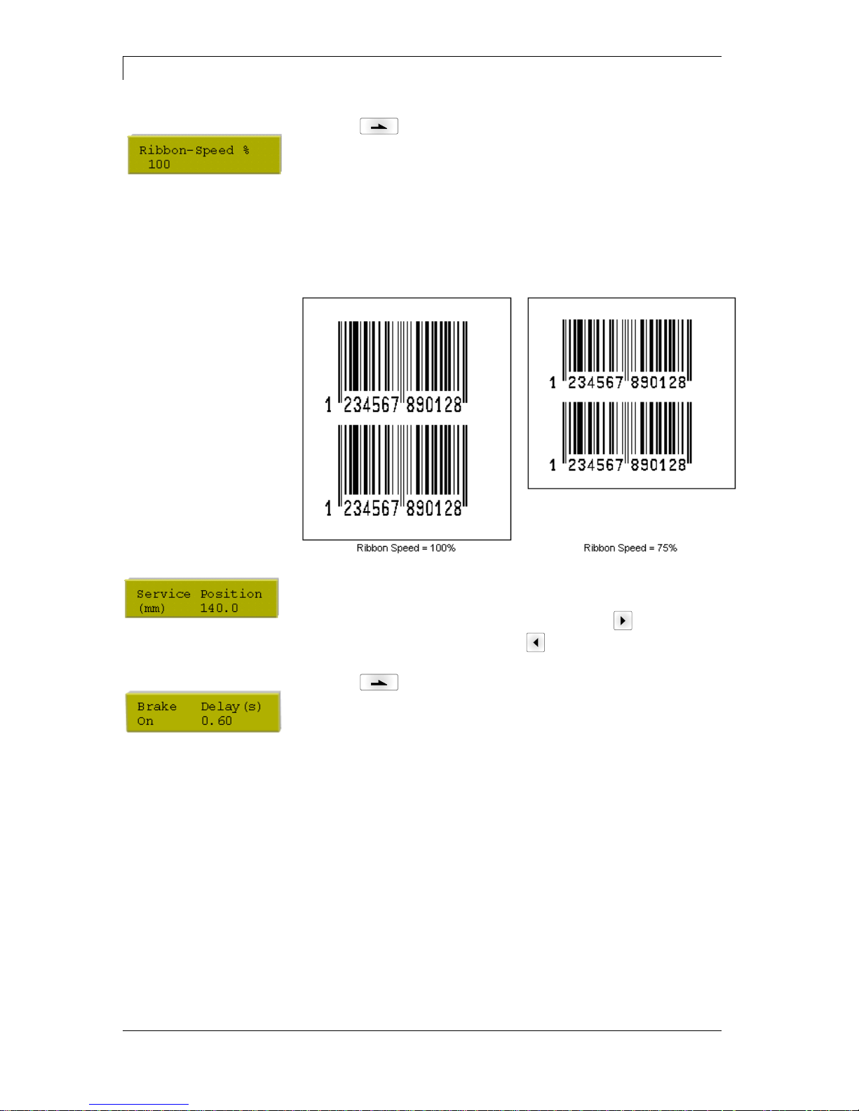
Ribbon speed:
Indication of ribbon speed in %.
In this mode it is possible to set the ribbon speed relative to the print
speed. Because of a less speed of the ribbon you can reduce the
consumption of ribbon. Reducing the ribbon speed can lead to an
inferior print quality.
The setting range of the ribbon speed is between 50% and 100%.
The example shows the consumption of transfer ribbon in
dependence of the ribbon speed.
Service position:
Indication of position in 1/10 mm steps in which the print unit can be
moved in times of service. In the main menu click key to move the
print unit in service position. Press key to move the print unit again
to zero point of machine.
Press key to arrive at the next menu item.
Brake:
In case the DPM III is installed in vertical position, the option brake
should be available and set to On. Is the DPM III installed in horizontal
or in variable position the option brake (if available) should be set to
Off to avoid deceleration during printing.
Delay:
Indication of delay in 1/100 seconds. By means of this parameter it is
possible to delay the closure of brake. If during the delay time no start
impulse for printing a new cycle is effected, then the brake is closed. If
the delay time is set to 0, the brake is closed immediate after return to
zero point of machine.

DPM III xi series
Function Menu
04.18
Operating manual
45
Press key to arrive at the next menu item.
Head delay:
With the 'head delay' parameter, the time between moving down and
start of movement of printing carriage can be set.
If fields are directly at the beginning of layout, the printhead is moved
down before the printing carriage starts to move. The necessary time
for moving down depends on the lift of printhead.
Default: 30 ms.
Press key to arrive at the next menu item.
Backfeed delay:
Setting of time between end of print cycle and beginning of return of
the printing carriage to the zero point.
Default: 50 ms.
7.4 Layout Settings
Press key to access the function menu.
Press key as long as you arrive at the 'Layout settings' menu.
Press key to select the menu.
Print length:
Indication of way which the print mechanics has to move. The print
length depends on the length of the print mechanics.
Press key to arrive at the next menu item.
Column printing:
Indication of width of one layout as well as how many layouts are
placed side by side (see chapter 12.1 Column Printing, on page 85).
Taste to arrive at the next menu item.
Material selection:
Selection of the used print media.
Press key to arrive at the next menu item.
Flip layout:
The axis of reflection is in the middle of the layout. If the layout width
was not transferred to the module, automatically the default layout
width i.e. the width of the printhead is used. Because of this reason
you have to note that the layout should have the same width as the
printhead as otherwise this could lead to problems in positioning.
Press key to arrive at the next menu item.
Rotate layout:
As default the layout is printed with 0° head forward. In case of an
activated function, the layout is rotated by 180° and it is printed in
reading direction.

Function Menu
DPM III xi series
46
Operating manual
04.18
Press key to arrive at the next menu item.
Alignment:
The adjustment of layout is effected only after 'flip/rotate label', i.e. the
adjustment is independent of the functions flip and rotate layout.
Left: The layout is aligned at the left-most position of printhead.
Centre: The layout is aligned at central point of printhead.
Right: The layout is aligned at right-most position of printhead.
7.5 Ribbon Save
Ribbon save = maximum utilisation of transfer ribbon
Press key to access the function menu.
Press key as long as you arrive at the 'Ribbon save' menu.
Press key to select the menu.
Press key so switch the ribbon save function On or Off.

DPM III xi series
Function Menu
04.18
Operating manual
47
7.6 Device Settings
Press key to access the function menu.
Press key as long as you arrive at the 'Device Settings' menu.
Press key to select the menu.
Field handling:
Off: The complete print memory is deleted.
Keep graphic: A graphic res. a TrueType font is transferred to the
direct print module once and stored in the direct print module internal
memory. For the following print order only the modified data is
transferred to the direct print module. The advantage is the saving of
transmitting time for the graphic data.
The graphic data created by the direct print module itself (internal
fonts, bar codes, ...) is generated only if they were changed. The
generating time is saved.
Delete graphic: The graphics res. TrueType fonts stored in the
internal memory is deleted but the other fields are kept.
Press key to arrive at the next menu item.
Codepage:
Indication of the font used in the direct print module.
The following possibilities are available:
ANSI character set / Codepage 437 / Codepage 850 / GEM German /
GEM English / GEM French / GEM Swedish / GEM Danish.
Press key to arrive at the next menu item.
External parameters:
Layout dimension only: The parameters for layout length, gap
length and layout width can be transferred to the printing system. All
other parameter settings are to be made directly at the printing
system.
On: Sending parameters such as print speed and contrast via our
creation software to the printing system. Parameters which are set
directly at the printing system before are no longer considered.
Off: Only settings made directly at the printing system are considered.
Press key to arrive at the next menu item.
Buzzer:
An acoustic signal is audible when pressing a key.
Value range: 1…7.
Off: No signal is audible.
Display:
Setting the contrast of display.
Value range: 0…7
Press key to arrive at the next menu item.
Language:
Selection of language in which you want to display the text in the
display.
At the moment the following languages are available: German,
English, French, Spanish, Portuguese, Dutch, Italian, Danish, Finnish,
Polish

Function Menu
DPM III xi series
48
Operating manual
04.18
Press key to arrive at the next menu item.
Keyboard layout:
Selection of region for the desired keyboard layout.
The following possibilities are available: Germany, England, France,
Greece, Spain, Sweden and US.
Press key to arrive at the next menu item.
Customized entry:
On: The question referring the customized variable appears once
before the print start at the display.
Auto: The question referring the customized variable appears after
every printed layout.
Off: No question appears at the display. In this case the stored default
value is printed.
Press key to arrive at the next menu item.
Hotstart:
On: Continue an interrupted print order after switching on the direct
print module anew.
Off: After switching off the direct print module the complete data is
lost (see chapter 12.2, on page 86).
Press key to arrive at the next menu item.
Password:
By a password several functions can be blocked, so the user cannot
work with them. There are several applications in which the use of
password protection makes sense
(see chapter 12.2, page 86).
Press key to arrive at the next menu item.
Layout confirmation:
On: A new print order is only printed after confirmation at the device.
An already active continuing print order is printed as long as the
confirmation is effected at the device.
Off: No query appears at the display of control unit.
P/Me (print after measuring):
On: If an error occurred during printing, whose removal can be
recognized by the module (e.g. transfer ribbon end, cassette open),
then the module changes after the error correction (e.g. cassette
closed again) immediately in the 'ready' mode.
Off: After removal and confirmation of error, the module changes into
'stopped' mode.
Press key to arrive at the next menu item.
Standard layout:
On: If a print order is started without previous definition of layout, the
standard layout is printed.
Off: If a print order is started without previous definition of layout, an
error message appears in the display.

DPM III xi series
Function Menu
04.18
Operating manual
49
7.7 I/O Parameters
Press key to access the function menu.
Press key as long as you arrive at the 'I/O Parameter' menu.
Press key to select the menu.
IN signal level:
Indication of signal at which a print order is started.
+
= active signal level is 'high' (1)
−
= active signal level is 'low' (0)
x
= not activated signal level
s
= status can be affected by interface*
The modification of the signal level is only taken into consideration for
the operating modes I/O static, I/O dynamic, I/O static continuous and
I/O dynamic continuous.
Press key to arrive at the next menu item.
OUT signal level:
Indication of signal level for output signal.
+
= active signal level is 'high) (1)
−
= active signal level is 'low' (0)
s
= Zustand kann über Schnittstelle beeinflusst werden*
Press key to arrive at the next menu item.
Debounce:
Indication of debounce time of the dispenser input. The setting range
of the debounce time is between 0 and 100 ms.
In case the start signal is not clear then you can debounce the input
by means of this menu item.
Press key to arrive at the next menu item.
Start signal delay:
Indication in time per second of the delay for the start signal.
Value range: 0.00 to 9.99.
Press key to arrive at the next menu item.
IO protocol:
Indication of interface at which the modifications of input signals and
output signals (I/O) are sent.
Press key to arrive at the next menu item.
Save signal
On: The start signal for the next label can already be released during
printing the current label. The signal is registered from the printer. The
printer starts printing the next label immediately after finishing the
current one. Therefore time can be saved and performance be
increased.
Off: The start signal for the next label can only be released if the
current label is printed to the end and the printer is again in 'waiting'
state (output 'ready' set). If the start signal was released already
before, so this is ignored.
*
in combination with Netstar PLUS

Function Menu
DPM III xi series
50
Operating manual
04.18
Press key to arrive at the next menu item.
Ready while printing:
Indication if the output signal 'print ready' (Out 5, Output II) remains
active while printing.
Off: At print start the 'print ready' signal is inactive (default setting).
On: At print start the 'print ready' signal remains active.
7.8 Network (DPM IIIxi optional only)
Press key to access the function menu.
Press key as long as you arrive at the 'Network' menu.
It is only possible to select this menu item in case a network card is
recognised at switching on the printer, otherwise a message appears
that the option is not available.
For more information, please see the separate manual.

DPM III xi series
Function Menu
04.18
Operating manual
51
7.9 Interface
Press key to access the function menu.
Press key as long as you arrive at the 'Interface' menu.
Press key to select the menu.
COM1:
0 - serial interface Off.
1 - serial interface On.
2 - serial Interface On, no error message occurs in case of a
transmission error.
Baud rate:
Indication of bits which are transferred per second.
Following values are possible: 1200, 2400, 4800, 9600, 19200.
P = Parity:
N - No parity; E - Even; O - Odd
Please observe that the settings correspond to those of the direct print
module.
D = Data bits:
Setting of data bits.
Value range: 7 or 8 Bits.
S = Stop bits:
Indication of stop bits between bytes.
Value range: 1 or 2 stop bits.
Press key to arrive at the next menu item.
SOH: Start of data transfer block Hex format 01
ETB: End of data transfer block Hex formal 17
Two different start / en signs can be set. The settings are normally
SOH = 01 HEX and ETB = 17 HEX. Several host computers cannot
process these signs and therefore SOH = 5E HEX and ETB = 5F
cannot be set.
Press key to arrive at the next menu item.
Data memory:
Standard: After starting a print order the direct print module buffer
receives data as long as it is filled.
Advanced: During a current print order data is received and
processed.
Off: After starting a print order no more data is received.
Press key to arrive at the next menu item.
Parallel port:
SPP - Standard Parallel Port
ECP - Extended Capabilities Port (enables a fast data transmission
but it is only to set at PCs of newer version).
Observe that the settings correspond to those of the PC.
Function Menu
DPM III xi series
52
Operating manual
04.18
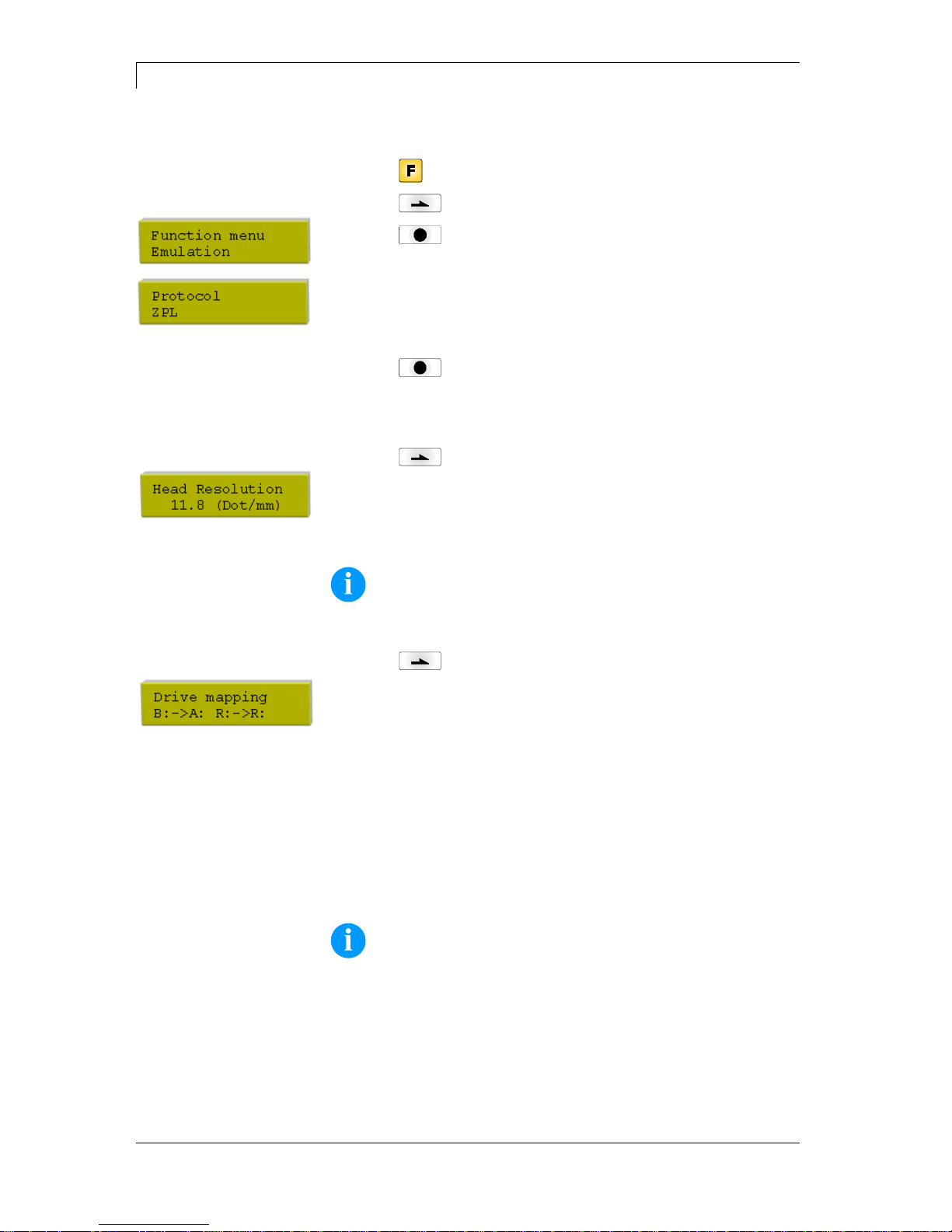
7.10 Emulation
Press key to access the function menu.
Press key as long as you arrive at the 'Emulation' menu.
Press key to select the menu.
Protocol:
CVPL: Carl Valentin Programming Language
ZPL: Zebra® Programming Language
Change between CVPL protocol and ZPL II® protocol.
Press key to confirm the selection.
The printer performs a restart and ZPL II® commands are transformed
into CVPL commands internally by the printer and then executed by
the printer.
Press key in menu protocol to arrive at the next menu item.
Printhead resolution:
At activated ZPL II® emulation the printhead resolution of the emulated
printer must be set, e.g. 11.8 Dot/mm (= 300 dpi).
NOTICE!
If the printhead resolution of the Zebra® printer differs from that
of the Valentin device, then the size of objects (e.g. texts,
graphics) complies not exactly.
Press key to arrive at the next menu item.
Drive mapping:
The access to Zebra® drives
B: Memory Card
R: RAM Disk (standard drive, if not indicated)
is rerouted to the corresponding Valentin drives
A: Memory Card (slot 1) and/or Compact Flash
B: Memory Card (slot 2)
R: RAM Disk
This can be necessary if the available space on the RAM disk (at
present. 512 KByte) is not sufficient or if bitmap fonts are downloaded
to the printer and be stored permanently.
NOTICE!
As the printer build-in fonts in Zebra® printers are not available
in Valentin devices, this can cause small differences in the text
image.

DPM III xi series
Function Menu
04.18
Operating manual
53
7.11 Date & Time
Press key to access the function menu.
Press key as long as you arrive at the 'Date/Time' menu.
Press key to select the menu.
Set date and time:
The upper line of display shows the current date, the second line the
current time. Press keys to arrive the next field. Press keys
and to increase and/or decrease the figures at the cursor position.
Press key to arrive at the next menu item.
Summertime:
On: Direct print module automatically adjust clock for daylight saving
changes.
Off: Summertime is not automatically recognized and adjusted.
Press key to arrive at the next menu item.
Start of summertime (format):
Select the format in which you want to define beginning summertime.
The above example indicates the default setting (European format).
DD = day, WW = week, WD = weekday, MM = month, YY = year,
next day = only next day is taken into consideration
Press key to arrive at the next menu item.
Start of summertime (date):
By means of this function you can enter the date at which summertime
has to start. This entry refers to the previously selected format.
Example: summertime is automatically adjusted at last Sunday in
March (03).
Press key to arrive at the next menu item.
Start of summertime (time):
By means of this function you can define the time when you want to
start summertime.
Press key to arrive at the next menu item.
End of summertime (format):
Select the format in which you want to define end of summertime.
The above example indicates the default setting (European format).
Press key to arrive at the next menu item.
End of summertime (date):
By means of this function you can define the date when you want to
stop summertime. The entry refers to the previously selected format.
Example: summertime is automatically adjusted at last Sunday in
October (10).
Press key to arrive at the next menu item.
End of summertime (time):
By means of this function you can define the time when you want to
stop summertime.
Press key to arrive at the next menu item.
Time shifting:
By means of this function you can enter time shifting in hours and
minutes (for automatically adjustment from summer and wintertime).
This entry refers to the currently set direct print module time.

Function Menu
DPM III xi series
54
Operating manual
04.18
7.12 Service Functions
NOTICE!
So that the distributor res. the direct print module manufacturer
in case of service can offer fast support all necessary
information such as selected parameters can be taken directly
from the device.
Press key to access the function menu.
Press key as long as you arrive at the 'Service Function' menu.
Press key to select the menu.
Photocell parameters:
Start = Indication of Start photocell (0 or 1) status.
End = Indication of End photocell (0 or 1) status.
TR = Indication of transfer ribbon photocell status (0 or 1).
P = Pressure:
Indication of value for compressed-air control (0 or 1).
H = Head:
Indication of value 0 or 1 for the position of machine cover.
0 - cover open, 1 - cover closed
Press key to arrive at the next menu item.
Paper counter:
D: Indication of printhead attainment in meters.
G: Indication of direct print module attainment in meters.
Press key to arrive at the next menu item.
Heater resistance:
To achieve a high print quality, the indicated Ohm value must be set
after an exchange of printhead.
Press key to arrive at the next menu item.
Printhead temperature:
Indication of printhead temperature. The printhead temperature
corresponds normally to the room temperature. In case the maximum
printhead temperature is exceeded, the current print order is
interrupted and an error message appears at the direct print module
display.
Press key to arrive at the next menu item.
Motor / Ramp:
The higher the '++' value is set, the slower the feeding motor is
accelerated.
The smaller the '−−' value is set, the faster the feeding motor is
limited.
This function is often used for high printing speed as the tearing of
transfer ribbon can be prevented.

DPM III xi series
Function Menu
04.18
Operating manual
55
Press key to arrive at the next menu item.
Print examples:
Settings: Printout of all settings such as speed, and transfer ribbon
material.
Bar codes: Printout of all available bar code types.
Fonts: Printout of all available font types.
Press key to arrive at the next menu item.
Input/Output:
Indication of signal level which indicates the signal a print order is
started.
0 - Low
1 – High
Press key to arrive at the next menu item.
Online/Offline:
This function is activated e.g. if the transfer ribbon is to be changed. It
is avoided that a print order is processed although the module is not
ready. If the function is activated then press the key to change
between Online and Offline mode. The respective state is indicated in
the display.
Standard: Off
Online: Data can be received by interface. The keys of the foil
keyboard are only active, if you changed in the Offline mode with key
.
Offline: The keys of the foil keyboard are still active but received data
are not processed. If the module is again in Online mode then new
print orders can be again received.
Press key to arrive at the next menu item.
TRB = Transfer ribbon advance warning:
Before the end of transfer ribbon, a signal is send by the control
output.
Warning diameter:
Setting of transfer ribbon advance warning diameter.
In case you enter a value in mm then a signal appears via control
output when reaching this diameter (measured at transfer ribbon roll).
Ribbon advance warning mode:
Warning: When reaching the transfer ribbon advance warning
diamter, the corresponding I/O output is set.
Reduced print speed: Speed on which the printing speed is to be
reduced.
Error: The printing system stops when reaching the transfer ribbon
advance warning diameter with the message 'too less ribbon'.
Reduced print speed:
Setting of the reduced print speed in mm/s. This can be set in the
limits of the normal print speed.

Function Menu
DPM III xi series
56
Operating manual
04.18
7.13 Main Menu
After switching on the direct print module the left indicated display
shows the following:
The first line of main menu indicates used device type.
The second line indicates current date and time.
Press key and the display shows the following:
The second line of display indicates version number of firmware.
After a short time the indication of display returns automatically to
main menu.
Press again key and the display shows the following:
Indication of software Build version.
Press again key and the display shows the following:
Indication of firmware creation date.
Press again key and the display shows the following:
Indication of firmware creation time.
Press again key and the display shows the following:
Indication of font version of bitmap fonts.
Press again key and the display shows the following:
Indication of font version of vector fonts.
Press again key and the display shows the following:
The second line of display indicates version numbers of both FPGA
(P = printhead; I = I/O).
Press again key and the display shows the following:
Indication of version number of boot software.
Press again key and the display shows the following:
Indication of memory size of FLASHs in MB.

DPM III xi series
Compact Flash Card
04.18
Operating manual
57
8 Compact Flash Card
This print module series are equipped with a slot for Compact Flash
card. By means of this memory card you can permanently save via
interface graphics, text, layout data or information from database.
HINWEIS!
In case of a malfunction of your original memory card we
recommend a copy of your most important data. Please use a
commercial Compact Flash reader for PC.
Insert Compact Flash card with contact side forwards to the slot that
was planned for it.
In order to prevent wrong insertion of cards, both sides of Compact
Flash cards have different guiding.
A small part of Compact Flash card is visible at the support at the
direct print module rear, so you can remove the card easily with hand.
HINWEIS!
Please note that we support only Compact Flash cards of type 1
at the moment. The use of micro drives is not intended at this
time.
The direct print module handles your Compact Flash card as a DOS
compatible file system.
After formatting Compact Flash card the STANDARD directory is
automatically available. After switching on the direct print module or
inserting Compact Flash card, this directory is the current one. Main
and sub-directories are indicated in <> (e.g. <Directory>).
HINWEIS!
The maximum length of directory is 254 characters. It is not
allowed to use the following characters neither in file nor in
directory names:
: \ " * / < > ? |
Insertion and removal
of Compact Flash card
File and/or
directory name

Compact Flash Card
DPM III xi series
58
Operating manual
04.18
Press key to indicate the saved layouts onto the Compact Flash
card.
Press key to enter the Compact Flash card menu.
Press key to arrive at the next menu item.
Press key to return to the previous menu item.
Press key to select a menu and to confirm a query.
Press key and to browse the contents of the current directory.
Press key and to change to the indicated directory.
NOTICE!
Before first use of Compact Flash card in your direct print module
we recommend to format the card in your direct print module.
Keys:
Press key and to select the desired label in STANDARD
directory.
Press key to select the layout.
Select the number of layouts which you want to print.
Press key to start the print order.
After finishing the print order the display shows again the main menu.
NOTICE!
It is NOT possible to change the directory. Enter the menu
'Change dir' to change the directory.
Navigation
Selecting layout

DPM III xi series
Compact Flash Card
04.18
Operating manual
59
Keys: ,
Press key to select the 'Load file' menu item.
Select the file you want to load and confirm the selection with key
.
The loaded layout is now in the printer internal storage and after the
loading procedure the display shows the main menu.
Press key and enter the desired number you want to print.
Confirm the selection with and the print order is started by an
external signal (Input 1, PIN 1 and PIN 4).
Keys: , ,
Press key to select the 'Save layout' menu item.
Select the directory and/or layout you want to save and confirm the
selection with key .
Confirm the query with and the layout will be saved.
After the saving procedure the display shows again the main menu.
Keys: , , ,
Press key to select the 'Save configuration' menu item.
As standard, the proposed file name is config.cfg. This name can be
changed by the user. In this file the parameters of print module are
saved which are not saved permanent in the internal Flash.
Press key to start the saving procedure.
After the saving procedure, the display shows again the main menu.
Loading file from
Compact Flash card
Saving layout onto
Compact Flash card
Saving the
configuration

Compact Flash Card
DPM III xi series
60
Operating manual
04.18
Keys: , , , ,
Press key to select the 'Change directory' menu item.
The lower line of display shows the directory which is selected at the
moment.
Press key and to change the directory in the upper line.
Press key and to show all available directories.
Press key to confirm the selected directory.
After changing the directory the display shows again the main menu.
Keys: , , , , ,
Press key to select the 'Delete file' menu item.
Select directory and/or layout you want to delete and confirm the
selection with key .
The selected layout is deleted from the Compact Flash card.
After the deleting procedure the display shows again the first menu
item 'Load file'.
Changing the directory
Deleting file from
Compact Flash card

DPM III xi series
Compact Flash Card
04.18
Operating manual
61
NOTICE!
The formatting procedure is recommended before using the
Compact Flash card for the first time in the label printer.
Keys: , , , , , ,
Press key to select the 'Format' menu item.
Press key to confirm the selection and the procedure is
started.
When formatting the Compact Flash card the STANDARD directory is
automatically created.
After the formatting procedure the display shows again the 'Load file'
menu item.
Keys: , , , , , , ,
Press key to select the 'Free memory' menu item.
The still available memory space onto Compact Flash card is
indicated.
Press key to display again the 'Load file' menu item.
Formatting Compact
Flash card
Indication of free
memory space


DPM III xi series
Maintenance and Cleaning
04.18
Operating manual
63
9 Maintenance and Cleaning
DANGER!
Risk of death by electric shock!
Disconnect the direct print module from power supply
before performing any maintenance work.
NOTICE!
When cleaning the label printer, personal protective equipment
such as safety goggles and gloves are recommended.
Maintenance task
Frequency
General cleaning
(see chapter 9.1, page 63).
As necessary.
Cleaning transfer ribbon
drawing roller (see section 9.2,
page 64).
Each time the transfer ribbon is
changed or when the printout is
adversely affected.
Cleaning printhead
(see chapter 9.3, page 64).
Each time the transfer ribbon is
changed or when the printout is
adversely affected.
Replacing printhead
(see chapter 9.4, page 65).
In case of errors in printout.
NOTICE!
The handling instructions for the use of Isopropanol (IPA) must
be observed. In the case of skin or eye contact, immediately
wash off the fluid thoroughly with running water. If the irritation
persists, consult a doctor. Ensure good ventilation.
9.1 General Cleaning
CAUTION!
Abrasive cleaning agents can damage the direct print
module!
Do not use abrasives or solvents to clean the outer
surface of the direct print module.
Remove dust and paper fuzz in the printing area with a soft
brush or vacuum cleaner.
Clean outer surfaces with an all-purpose cleaner.
Maintenance
chedule

Maintenance and Cleaning
DPM III xi series
64
Operating manual
04.18
9.2 Cleaning the Transfer Ribbon Drawing Roller
A soiled print roll can lead to reduced print quality and can affect
transport of material.
1. Remove cover.
2. Remove transfer ribbon from the direct print module.
3. Remove deposits with roller cleaner and a soft cloth.
4. If the roller (A) appears damaged, replace it.
9.3 Cleaning the Printhead
Printing can cause accumulation of dirt at printhead e.g. by colour
particles of transfer ribbon, and therefore it is necessary to clean the
printhead in regular periods depending on operating hours,
environmental effects such as dust etc.
CAUTION!
Printhead can be damaged!
Do not use sharp or hard objects to clean the
printhead.
Do not touch protective glass layer of the printhead.
1. Remove transfer ribbon cassette.
2. Clean printhead surface with special cleaning pen or a cotton
swab dipped in pure alcohol.
3. Allow printhead to dry for 2-3 minutes before commissioning the
device.

DPM III xi series
Maintenance and Cleaning
04.18
Operating manual
65
9.4 Replacing the Printhead
Figure 22
CAUTION!
The printhead can be damaged by static
electricity discharges and impacts!
Set up direct print module on a grounded,
conductive surface.
Ground your body, e.g. by wearing a
grounded wristband.
Do not touch contacts on the plug
connections.
Do not touch printing line (5) with hard
objects or your hands.
1. Remove transfer ribbon material.
2. Move printhead unit in an appropriate service position.
3. Remove printhead cable (1).
4. Remove screws (2) and afterwards the printhead (3).
1. Do not touch the contacts of printhead.
2. Position the printhead in the printhead support.
3. Screw again screws (2) and tighten it.
4. Connect again printhead cable (1).
5. Insert again the transfer ribbon material (see 5.8. on page 33).
6. Start a test print to check printhead position.
7. Enter the resistance value of the new printhead in the 'Service
Functions' (heater resistance). The value is indicated on the type
plate of printhead.
Removing the
printhead
Installing the printhead

Maintenance and Cleaning
DPM III xi series
66
Operating manual
04.18
9.5 Transfer Ribbon Tension
Figure 23
For a regular print quality it is necessary that the transfer ribbon is to
tighten even over its width. With the nuts (1) it is possible to regulate a
different transfer ribbon tension by a sideways overturn of the
printhead.
CAUTION!
Folding at transfer ribbon!
Change factory settings only in exceptional cases.
1. By loosen a nut the printhead moves down at the corresponding
side.
The transfer ribbon tension is increased.
2. By tightening a nut the printhead moves up at the corresponding
side.
The transfer ribbon tension is reduced.
NOTICE!
A strong regulation has result to the pressure power of
printhead.
3. Start a print order with approx. 3 layouts to check the correct
unwrinkled ribbon run.

DPM III xi series
Maintenance and Cleaning
04.18
Operating manual
67
9.6 Angle Adjustment
Figure 24
The installation angle of the printhead is default 26° to the print
surface. However, manufacturing tolerances of printhead and
mechanics can require another angle.
CAUTION!
Damage of printhead by unequal use!
Higher wastage of ribbon by faster ripping.
Change factory settings only in exceptional cases.
1. Loosen slightly two Allen head screws (2).
2. Move setscrews (1) to adjust the angle between printhead and
printhead support.
Tighten = decrease angle
Loosen = increase angle
3. Beide Gewindestifte sind immer gleich weit zu verdrehen.
4. Tighten again the Allen head screws (2).
5. Start a print order with approx. 3 layouts to check the correct
unwrinkled ribbon run.
NOTICE!
The slots serve for position control. Pay attention to a parallel
adjustment.

Maintenance and Cleaning
DPM III xi series
68
Operating manual
04.18
9.7 Zero Point Adjustment
Figure 25
By means of a slider (1) you have the possibility to change the printer
zero point.
In case the slider is at the end of its guiding then the maximum print
length is available.
If you change the zero point the way from zero point to the print start
is shortened. Moreover you can use the change of zero point to
change the printhead position of the foil which is to be printed.
By changing the zero point of printer the print area is more shorten.

DPM III xi series
Maintenance and Cleaning
04.18
Operating manual
69
9.8 Print Quality Optimisation
The following table shows some possibilities to improve the print
quality.
Generally you have to note: the higher the print speed the lower the
print quality.
Problem
Possible solution
Regular inferior print quality
Increase contrast
Increase pressure
Control 'alternative' transfer ribbon guiding
Reduce print speed
Reduce transfer ribbon speed
Reduce distance between printhead and print
surface
Change combination of transfer ribbon and print
medium
Control print surface (hardness)
Change printhead angle
Partial inferior print quality
(on one side)
Align surface parallel to printhead
Set regular transfer ribbon tension
Set regular printhead angle
Partial inferior print quality (periodical)
Sharp surface even
Reinforce surface against bending

Maintenance and Cleaning
DPM III xi series
70
Operating manual
04.18
9.9 Cycle Optimisation
Taktzahl = abgeschlossener Druckzyklus pro Zeiteinheit.
Figure 26
In case of 'time critical' applications you have the possibility with a
good selection of different device parameters to increase the effective
print speed and it this way the clock cycle.
Generally increase the print speed.
Generally increase the back speed.
Increase acceleration and brake ramp.
Change zero point of machine.
Avoid vertical installation position of print mechanics. Install the
machine in horizontal position.
Control the short distance between printhead and print surface.
Optimise the layout to a short print way, i.e. less blanks, no
borders at the top res. bottom, rotate the layout.

DPM III xi series
Signal Diagrams
04.18
Operating manual
71
10 Signal Diagrams
10.1 Mode 1 (single item processing)

Signal Diagrams
DPM III xi series
72
Operating manual
04.18
10.2 Mode 2 (continuous mode)

DPM III xi series
Signal Diagrams
04.18
Operating manual
73
10.3 Mode 4 (continuous mode)
Return without 'layout
printing' signal

Signal Diagrams
DPM III xi series
74
Operating manual
04.18
10.4 Mode 8 (single item processing)
Return without 'layout
printing' signal

DPM III xi series
Error Correction
04.18
Operating manual
75
11 Error Correction
Error message
Cause
Remedy
1
Line too high
Line rises up completely or
partly over the upper edge of
label.
Move line down
(increase Y value).
Check rotation and font.
2
Line too low
Line rises up completely or
partly over the bottom edge of
label.
Move line up (reduce Y value).
Check rotation and font.
3
Character set
One res. several characters of
the text is res. are not available
in the selected font.
Change text.
Change font.
4
Unknown code type
Selected code is not available.
Check code type.
5
Invalid position
Selected position is not
available.
Check position.
6
CV font
Selected font is not available.
Check font.
7
Vector font
Selected font is not available.
Check font.
8
Measuring label
While measuring no label was
found.
Set label length is too large.
Check label length and if labels
are inserted correctly.
Restart measuring anew.
9
No label found
No label available.
Soiled label photocell.
Labels not inserted correctly.
Insert new label roll.
Check if labels are inserted
correctly.
Clean the label photocell.
10
No ribbon
During the print order the
ribbon roll becomes empty.
Defect at the transfer ribbon
photocell.
Change transfer ribbon.
Check transfer ribbon photocell
(service functions).
11
COM FRAMING
Stop bit error.
Check stop bits.
Check baud rate.
Check cable (printer and PC).
12
COM PARITY
Parity error.
Check parity.
Check baud rate.
Check cable (printer and PC).
13
COM OVERRUN
Loss of data at serial interface
(RS-232).
Check baud rate.
Check cable (printer and PC).
14
Field numer
Received line number is invalid
at RS-232 and Centronics.
Check sent data.
Check connection PC - printer.
15
Length mask
Invalid length of received mask
statement.
Check sent data.
Check connection PC - printer.

Error Correction
DPM III xi series
76
Operating manual
04.18
Error message
Cause
Remedy
16
Unknown mask
Transferred mask statement is
invalid.
Check sent data.
Check connection PC - printer.
17
Missing ETB
No end of data found.
Check sent data.
Check connection PC - printer.
18
Invalid character
One res. several characters of
the text is res. are not available
in the selected font.
Change text.
Change font.
19
Invalid statement
Unknown transferred data
record.
Check sent data.
Check connection PC - printer.
20
Invalid check digit
For check digit control the
entered res. received check
digit is wrong.
Calculate check digit anew.
Check code data.
21
Invalid SC number
Selected SC factor is invalid for
EAN res. UPC.
Check SC factor.
22
Invalid number of
digits
Entered digits for EAN res.
UPC are invalid
< 12; > 13.
Check number of digits.
23
Check digit
calculation
Selected check digit calculation
is not available in the bar code.
Check calculation of check
digit.
Check bar code type.
24
Invalid extension
Selected zoom factor is not
available.
Check zoom factor.
25
Offset sign
Entered sign is not available.
Check offset value.
26
Offset value
Entered offset value is invalid.
Check offset value.
27
Printhead
temperature
Printhead temperature is too
high.
Defective printhead sensing
device.
Reduce contrast.
Change printhead.
28
Cutter error
With cut an error occurred.
Paper jam.
Check label run.
Check cutter run.
29
Invalid parameter
Entered data do not correspond
to the characters allowed from
the application identifier.
Check code data.
30
Application
Identifier
Selected application identifier is
not available in GS1-128.
Check code data.
31
HIBC definition
F Missing HIBC system sign.
Missing primary code.
Check definition of HIBC code.

DPM III xi series
Error Correction
04.18
Operating manual
77
Error message
Cause
Remedy
32
System clock
Real Time Clock function is
selected but the battery is
empty.
Defective RTC.
Change battery.
Change RTC component.
33
No CF interface
Interrupted connection CPU CF card.
Defective CF card interface.
Check connection CPU - CF
card interface.
Check CF card interface.
34
No print memory
No print CF found.
Check CF assembly on CPU.
35
Printhead open
At start of a print order the
printhead is open.
Close the printhead and start
print order anew.
36
BCD invalid format
BCD error
Invalid format for the
calculation of Euro variable.
Check entered format.
37
BCD overflow
BCD error
Invalid format for the
calculation of Euro variable.
Check entered format.
38
BCD division
BCD error
Invalid format for the
calculation of Euro variable.
Check entered format.
39
FLASH ERROR
Flash component error.
Run a software update.
Change CPU.
40
Length command
Invalid length of the received
command statement.
Check data sent.
Check connection PC - printer.
41
No drive
CF card not found / not
correctly inserted.
Insert CF card correctly.
42
Drive error
Impossible to read CF card
(faulty).
Check CF card, if necessary
change it.
43
Not formatted
CF Card not formatted.
Format CF card.
44
Delete current
directory
Attempt to delete the actual
directory.
Change directory.
45
Path too long
Too long indication of path.
Indicate a shorter path.
46
Drive writeprotected
Memory card is write-protected.
Deactivate write protection.
47
Directory not file
Attempt to indicate a directory
as file name.
Correct your entry.
48
File already open
Attempt to change a file during
an access is active.
Select another file.
49
No file/directory
File does not exist on CF card.
Check file name.

Error Correction
DPM III xi series
78
Operating manual
04.18
Error message
Cause
Remedy
50
Invalid file name
File name contains invalid
characters.
Correct entry of name, remove
special characters.
51
Internal file error
Internal file system error.
Please contact your distributor.
52
Root full
The max. number (64) of main
directory entries is reached.
Delete at least one main
directory entry and create
subdirectories.
53
Drive full
Maximum CF capacity is
reached.
Use new CF Card, delete no
longer required files.
54
File/directory
exists
The selected file/directory
already exists.
Check name, select a different
name.
55
File too large
During copying procedure not
enough memory space onto
target drive available.
Use a larger target card.
56
No update file
Errors in update file of
firmware.
Start update file anew.
57
Invalid graphic file
The selected file does not
contain graphic data.
Check file name.
58
Directory not empty
Attempt to delete a not empty
directory.
Delete all files and subdirectories in the desired
directory.
59
No interface
No CF card drive found.
Check connection of CF card
drive.
Contact your distributor
60
No CF card
No CF card is inserted.
Insert CF card in the slot.
61
Webserver error
Error at start of web server.
Please contact your distributor.
62
Wrong FPGA
The direct print module is
equipped with the wrong
FPGA.
Please contact your distributor.
63
End position
The label length is too long.
The number of labels per cycle
is too much.
Check label length res. the
number of labels per cycle.
64
Zero point
Defective photocell.
Change photocell.
65
Compressed air
Pressure air is not connected.
Check pressure air.
66
External releaser
External print release signal is
missing.
Check input signal.
67
Row too long
Wrong definition of column
width res. number of columns.
Reduce the column width res.
correct the number of columns.
68
Scanner
The connected bar code
scanner signals a device error.
Check the connection
scanner/printer.
Check scanner (dirty).

DPM III xi series
Error Correction
04.18
Operating manual
79
Error message
Cause
Remedy
69
Scanner NoRead
Bad print quality.
Printhead completely soiled or
defective.
Print speed too high.
Increase contrast.
Clean printhead or exchange (if
necessary).
Reduce print speed.
70
Scanner data
Scanned data does not
correspond to the data which is
to print.
Exchange printhead.
71
Invalid page
As page number either 0 or a
number > 9 is selected.
Select a number between 1
and 9.
72
Page selection
A page which is not available is
selected.
Check the defined pages.
73
Page not defined
The page is not defined.
Check the print definition.
74
Format user guiding
Wrong format for customised
entry.
Check the format string.
75
Format date/time
Wrong format for date/time.
Check the format string.
76
Hotstart CF
No CF card found.
If option hotstart was activated,
a CF card must be inserted.
Switch off the printer before
inserting the memory card.
77
Flip/Rotate
Selection of print of several
columns and also mirror/rotate.
It is only possible to select one
of both functions.
78
System file
Loading of temporary hotstart
files.
Not possible.
79
Shift variable
Faulty definition of shift times
(overlapping times).
Check definition of shift times.
80
GS1 Databar
General GS1 Databar error.
Check definition and parameter
of GS1 Databar code.
81
IGP error
Protocol error IGP.
Check sent data.
82
Time generation
Printing creation was still active
at print start.
Reduce print speed.
Use printers' output signal for
synchronisation.
Use bitmap fonts to reduce
generating time.
83
Transport protection
Both DPM position sensors
(start/end) are active.
Displace zero point sensor
Check sensors in service
functions menu
84
No font data
Font and web data is missing.
Run a software update.
85
No layout ID
Label ID definition is missing.
Define label ID onto the label.

Error Correction
DPM III xi series
80
Operating manual
04.18
Error message
Cause
Remedy
86
Layout ID
Scanned data does not
correspond to defined ID.
Wrong label loaded from CF
card.
87
RFID no label
RFID unit cannot recognise a
label.
Displace RFID unit or use an
offset.
88
RFID verify
Error while checking
programmed data.
Faulty RFID label.
Check RFID definitions
89
RFID timeout
Error at programming the RFID
label.
Label positioning.
Faulty label.
90
RFID data
Faulty or incomplete definition
of RFID data.
Check RFID data definitions.
91
RFID tag type
Definition of label data does not
correspond with the used label.
Check storage partitioning of
used label type
92
RFID lock
Error at programming the RFID
label (locked fields).
Check RFID data definitions.
Label was already
programmed.
93
RFID programming
Error at programming the RFID
label.
Check RFID definitions.
94
Scanner timeout
The scanner could not read the
bar code within the set timeout
time.
Defective printhead.
Wrinkles in transfer ribbon.
Scanner wrong positioned.
Timeout time too short.
Check printhead.
Check transfer ribbon.
Position scanner correctly,
corresponding to the set
feeding.
Select longer timeout time.
95
Scanner layout
difference
Scanner data does not
correspond to bar code data.
Check adjustment of scanner.
Check scanner settings /
connection.
96
COM break
Serial interface error.
Check settings for serial data
transmission as well as cable
(printer-PC).
97
COM general
Serial interface error.
Check settings for serial data
transmission as well as cable
(printer-PC).
98
No software
printhead FPGA
No printhead-FPGA data
available.
Please contact your
responsible distributor.
99
Load software
printhead FPGA
Error when programming
printhead-FPGA.
Please contact your
responsible distributor.
100
Upper position
Sensor signal up is missing
(option APL 100).
Check input signals /
compressed-air supply.

DPM III xi series
Error Correction
04.18
Operating manual
81
Error message
Cause
Remedy
101
Lower position
Sensor signal down is missing
(option APL 100).
Check input signals /
compressed-air supply.
102
Vacuum plate empty
Sensor does not recognise a
label at vacuum plate
(option APL 100).
Check input signals /
compressed-air supply.
103
Start signal
Print order is active but device
not ready to process it.
Check start signal.
104
No print data
Print data outside the defined
label.
Selection of wrong module type
(design software).
Check selected module type.
Check selection of left/right
version.
105
Printhead
No original printhead is used.
Check the used printhead.
Please contact your distributor.
106
Invalid Tag type
Wrong Tag type.
Tad data do not match the Tag
type in the printer.
Adapt data or use the correct
Tag type.
107
RFID invalid
RFID module is not activated.
No RFID data can be
processed.
Activate RFID module or
remove RFID data from label
data.
108
GS1-128 invalid
Transferred GS1-128 bar code
is invalid.
Verify bar code data (see GS1128 bar code specification).
109
EPC parameter
Error at EPC calculation.
Verify data (see EPC
specification).
110
Housing open
When starting the print order
the housing cover is not closed.
Close the housing cover and
start the print order anew.
111
EAN.UCC code
Transferred EAN.UCC code is
invalid.
Verify bar code data (see
corresponding specification).
112
Print carriage
Printing carriage does not
move.
Check gear belt (possibly
broken).
113
Applicator error
Error while using applicator.
Check applicator.
114
Left position
Left final position switch is not
in correct position.
Check LEFT final position
switch for correct function and
position.
Check function of pneumatics
for cross traverse.
115
Right position
Right final position switch is not
in correct position.
Check RIGHT final position
switch for correct function and
position.
Check function of pneumatics
for cross traverse.

Error Correction
DPM III xi series
82
Operating manual
04.18
Error message
Cause
Remedy
116
Print position
The print position is not correct.
Check TOP and RIGHT final
position switch for correct
function and position.
Check pneumatics for function
117
XML parameter
The parameters in the XML file
are not correct.
Please contact your
responsible distributor.
118
Invalid variable
Transferred variable is invalid
with customized entry.
Select correct variable without
customized entry and transfer
it.
119
No ribbon
During the print order the
ribbon roll becomes empty.
Defect at the transfer ribbon
photocell.
Change transfer ribbon.
Check transfer ribbon photocell
(service functions).
120
Wrong directory
Invalid target directory when
copying.
Target directory must not be
within the source directory.
Check target directory.
121
No label found
No label found at the rear
printhead (DuoPrint).
Soiled label photocell.
Labels not inserted correctly.
Insert new label roll.
Clean the label photocell.
Check if labels are inserted
correctly.
122
IP occupied
The IP address was already
assigned.
Assign a new IP address.
123
Print asynchronous
The label photocell does not
work in the order as it is
expected according to print
data.
Check label size and gap size.
The settings of the photocell
are not correct.
Check label photocell settings.
Settings of label size and gap
size are not correct.
Check correct loading of label
material.
No label found at the rear
printhead.
Insert new label roll.
Soiled label photocell.
Clean the label photocell.
Labels not inserted correctly.
Check if labels are inserted
correctly.
124
Speed too slow.
The print speed is too slow.
Increase the speed of
customers' machine.
125
DMA send buffer
Communication problem HMI.
Restart the printer.
126
UID conflict
Configuration RFID
programming faulty.
Run RFID initialising.

DPM III xi series
Error Correction
04.18
Operating manual
83
Error message
Cause
Remedy
127
Module not found
RFID module not available.
Check the RFID module
connection.
Please contact your
responsible distributor.
128
No release signal
No print release by higher-level
control (customer machine).
Activate release signal at the
higher-level control.
129
Wrong firmware
Firmware does not match the
used printer type.
Use firmware that fits to the
printer type.
Please contact your
responsible distributor.
130
Language missing
Language file for the set printer
language is not available.
Please contact your
responsible distributor.
131
Wrong material
Label material does not fit to
printing data.
User label material with
suitable label and/or gap
length.
132
Invalid mark-up tag
Invalid mark-up formatting
characters in text.
Correct the formatting
characters in the text.
133
Script not found
LUA script file not found.
Check the file name.
134
Script failure
LUA script is incorrect.
Check the script.
135
Script user error
Error in LUA script user input.
Correct the input value.
136
No reprint available
No label data for reprinting
available.
Send new label data to the
printer.
137
Printhead short
circuit
Electrical short at the printhead.
Check the used printhead.
Please contact your distributor.
138
Too little ribbon
Transfer ribbon ends.
Change transfer ribbon.


DPM III xi series
Additional Information
04.18
Operating manual
85
12 Additional Information
12.1 Column Printing
With this direct print module several columns can be printed, i.e. the
information of one column can be printed several times (depending on
its width) on a layout. Caused by this the use of the complete print
width is possible and the generating time is enormously reduced.
For example 4 columns with a width of 25 mm or 2 columns with a
width of 50 mm can be printed onto a layout with a width of 100 mm.
Please note that the first layout is always the one with the largest x
coordinate, i.e. it has the largest distance to the printhead.
Press key to change to the function menu.
Press key as long as to the 'Layout' menu.
Press key to confirm the selection.
Press key as long as the menu item (see illustration) appears.
Press key and to set the layout width. As column width the
width of one layout is entered, e.g. 20.0 mm.
Press key and to enter the number of columns.
Press key and to change the number of columns, e.g. 4
columns at a layout width of 20.0 mm.
Press key to start a print with indication of number of layouts and
number of lines. The number of layouts corresponds to the number of
layouts that are to print.
e.g. columns: 3, items: 4
The first four layouts were printed but not layout 5 and 6.
Setting the print of
several columns

Additional Information
DPM III xi series
86
Operating manual
04.18
12.2 Hotstart
NOTICE!
The data is saved onto CF card. Therefore the CF card is a
condition for the Hotstart menu item.
The function hotstart contains e.g. that in case of a power failure the
currently loaded layout can be further processed without any loss of
data.
Moreover a print order can be interrupted and to be continued after
switching on the printer anew.
NOTICE!
At an active hotstart all necessary data is stored on the
Compact Flash therefore do not remove the card during
operation. When removing during operation, this causes the
loss of all data on the Compact Flash Card.
In case the hotstart function is set to on, at the start of a print order the
data of the current layout is saved to the corresponding directory of
the Compact Flash card.
However the following conditions have to be fulfilled:
Compact Flash card inserted in drive A
Compact Flash card not write protected
Enough free storage space onto Compact Flash card
An error message appears in case these conditions are not fulfilled.
At switching off the printer the state of the current print order is saved
to the corresponding directory of the Compact Flash Card.
However the following conditions have to be fulfilled:
Compact Flash card inserted in drive A
Compact Flash card not write protected
Enough free storage space onto Compact Flash card
In case the hotstart function is set to On, at a new start of printer the
saved layout data and the print order state is loaded from the
corresponding file on the Compact Flash card. Because of this reason
a Compact Flash card has to be inserted at switching on the printer. In
case it is impossible to load the data an error message appears.
Saving the
current layout
Saving the printer
order state
Loading a layout and
printer order state

DPM III xi series
Additional Information
04.18
Operating manual
87
In case at switching off the direct print module a print order was
active, then a print start is released automatically and the required res.
actual number of printed layouts is refreshed.
In case the print order was stopped at switching off the direct print
module, it is again set to the stopped mode after switching on the
direct print module anew.
In case a customized entry was active during switching off the direct
print module, the window for the first customized variable is displayed.
As in the intended file only the start values of the counter are saved,
they are refreshed at a new start of the print order by means of the
number of printed layouts. Each counter is counted corresponding
from its start value. Afterwards the position of the current and the next
counter update are correctly set by means of the update intervals.
NOTICE!
Make sure that in case graphics are onto the layout they have
to be saved onto Compact Flash card.
Starting the print order
Refreshing the
variable counter

Additional Information
DPM III xi series
88
Operating manual
04.18
12.3 Password
The supervisor programs a Compact Flash memory card directly with
the direct print module. He stores 10 different layouts. As well he
adjusts the printer parameters, like contrast, speed, etc. to the
corresponding values. The user is only supposed to read the layouts
from memory card and to print them. Therefore the supervisor blocks
the function menu and the entry function by a password.
The printer is connected to a PC. The user is only supposed to take
the layouts dispensed by the printer and stick them on. To prevent,
that the layouts or the printer set-up will not be changed, the
supervisor blocks all printer functions (e.g. function menu, entry menu,
etc.) by a password.
The user has to change several texts before printing. It is not allowed
to change any masks (fonts, position, etc.). Therefore the supervisor
blocks the entry of mask and the function menu. By this means the
user indeed can print layouts, but the printer set-up and the masks of
the layouts can't be changed.
To receive a most flexible password protection, the printer functions
will be divided into several function groups:
In the function menu the printer parameters can be changed (contrast,
speed, mode, ...). The password protection prevents modifications at
the printer settings.
With the functions of your Compact Flash card layouts can be stored,
loaded, ....
Here the password protection has to separate, if none or only reading
functions are allowed.
With key quant a print can be produced. In case the printer is
connected to a PC, it can be useful, that the user is not able to
produce a print manually. So the password protection prevents that
prints can be produced manually.
Because of these different function groups the password protection is
very flexible. The printer can be adjusted best to its actual order, as
only certain functions are blocked.
Example 1
Example 2
Example 3
1. Function menu
2. Compact Flash card
3. Print functions

DPM III xi series
Additional Information
04.18
Operating manual
89
In case no password is defined res. the password protection is not
activated, all functions can be used. In the function menu you will find
the menu item "Password", where the password can be entered and
the password protection activated.
Press key as long as to the password menu.
Press key to confirm the selection.
Meaning of abbreviations:
F
Function menu
CF
Compact Flash card functions
D
Print functions
In case the password protection is active, but the function menu is not
protected, the password
(4-digit number between 0000 and 9999) has to be entered first, so
the above shown display appears. Now changes can be done. In the
first line the user can define the password (4-digit number).
Press key to continue.
Press key and to activate/deactivate the password protection
(yes/no).
Press key to change to the second line.
Press key and to block/release individual function groups.
Press key and to change from one group to the next one.
F:
Function menu
0…open
1…locked
CF:
Compact Flash card
0…open
1…only reading access
2…access blocked
D:
Printer guiding
0…open
1…open
2…no manual print release
In case the user wants to perform a blocked function, he has to enter
the valid password first.
The entered password has to be confirmed with E. In case the correct
password has been entered the desired function can be performed. If
the entered password was invalid no error message appears but the
main menu will be displayed.
Password definition
Activate blocked
function


DPM III xi series
Environmentally-Friendly Disposal
04.18
Operating manual
91
13 Environmentally-Friendly Disposal
Manufacturers of B2B equipment are obliged to take back and
dispose of old equipment that was manufactured after 13 August
2005. As a principle, this old equipment may not be delivered to
communal collecting points. It may only be organised, used and
disposed of by the manufacturer. Valentin products accordingly
labelled can therefore be returned to Carl Valentin GmbH.
This way, you can be sure your old equipment will be disposed of
correctly.
Carl Valentin GmbH thereby fulfils all obligations regarding timely
disposal of old equipment and facilitates the smooth reselling of these
products. Please understand that we can only take back equipment
that is sent free of carriage charges.
Further information on the WEEE directive is available on our website
www.carl-valentin.de.


DPM III xi series
Index
04.18
Operating manual
93
14 Index
C
Column printing .................................................................................. 85
Compact Flash card ......................................................... 57, 58, 59, 61
Connection ......................................................................................... 31
Connector assignment (control unit IP version), figure ...................... 11
Connector assignment (control unit), figure ....................................... 10
D
Delivery scope .................................................................................... 27
E
Environmentally-friendly disposal ....................................................... 91
Error messages/corrections ............................................................... 83
Error messages/Error corrections ...... 75, 76, 77, 78, 79, 80, 81, 82, 83
F
Figures
Connector assignment, control unit ................................................ 10
Connector assignment, control unit IP version ............................... 11
Print mechanics ................................................................................ 9
Function menu
Date/time ........................................................................................ 53
Device settings ......................................................................... 47, 48
Emulation ........................................................................................ 52
I/O parameters .......................................................................... 49, 50
Interface .......................................................................................... 51
Layout settings .......................................................................... 45, 46
Machine parameters ..................................................... 42, 43, 44, 45
Menu structure .......................................................................... 39, 40
Network (option) ............................................................................. 50
Print settings ................................................................................... 41
Ribbon save .................................................................................... 46
Service functions ...................................................................... 54, 55
H
Hotstart ......................................................................................... 86, 87
I
Initiation .............................................................................................. 32
Initiation, preparations ........................................................................ 31
Inputs/outputs ..................................... 18, 19, 20, 21, 22, 23, 24, 25, 26
Installation at machines ...................................................................... 28
Instructions ........................................................................................... 5
Intended use ..................................................................................... 5, 6

Index
DPM IIIxi Serie
94
Operating manual
04.18
K
Keyboard
Standard ......................................................................................... 35
Text entry/customized entry ..................................................... 36, 37
M
Machine overviews ............................................................................... 9
Main menu .......................................................................................... 56
Maintenance/cleaning
Angle adjustment ............................................................................ 67
Cleaning printhead .......................................................................... 64
Cycle optimisation ........................................................................... 70
General cleaning ............................................................................. 63
Print quality optimisation ................................................................. 69
Printhead, cleaning ......................................................................... 64
Replacing printhead .................................................................. 64, 65
Ribbon drawing roller, cleaning ...................................................... 64
Schedule ......................................................................................... 63
Transfer ribbon tension ................................................................... 66
Zero point adjustment ..................................................................... 68
O
Operating conditions ........................................................ 13, 14, 15, 16
P
Password protection ..................................................................... 88, 89
Pneumatic power supply, connection ................................................. 29
Print control ........................................................................................ 32
Print mechanics, figure ......................................................................... 9
Print principle ...................................................................................... 12
S
Safety instructions ............................................................................ 6, 7
Signal diagram
Mode 1 (single item processing) ..................................................... 71
Mode 2 (continuous mode) ............................................................. 72
Mode 4 (continuous mode, return without 'layout printing' signal) . 73
Mode 8 (single item processing, return without 'layout printing'
signal) .......................................................................................... 74
T
Technical data .................................................................................... 17
Transfer ribbon loading ...................................................................... 33
U
Unpacking .......................................................................................... 27


 Loading...