


APL 100
Operating Manual

Copyright by Carl Valentin GmbH / 7952505A11.13
Information on the scope of delivery, appearance, performance,
dimensions and weight reflect our knowledge at the time of printing.
We reserve the rights to make modifications.
All rights, including those regarding the translation, are reserved.
No part of this document may be reproduced in any form (print,
photocopy or any other method) or edited, copied or distributed
electronically without written permission from Carl Valentin GmbH.
Due to the constant further development of our devices discrepancies
between manual and device can occur.
Please check www.carl-valentin.de for the latest update.
Trademarks
Centronics
®
is a registered trademark of Data Computer Corporation.
Microsoft
®
is a registered trademark of Microsoft Corporation.
Windows 2000
®
, 2003®, XP®, Vista®, 7®, 8®, Windows ServerTM 2008,
Windows Server
TM
2008 R2, Windows ServerTM 2012 are registered
trademarks of Microsoft Corporation.
TrueType
TM
is a trademark of Apple Computer, Inc.
Zebra
®
and ZPL II® are registered trademarks of ZIH Corporation.
The pneumatic applicator complies with the following safety
guidelines:
CE
EG Low-Voltage Directive (2006/95/EC)
EG Electromagnetic Compatibility Directive (2004/108/EG)
EG Machinery Directive (2006/42/EG)
Carl Valentin GmbH
Postfach 3744
78026 Villingen-Schwenningen
Neckarstraße 78 – 86 u. 94
78056 Villingen-Schwenningen
Phone
Fax
+49 (0)7720 9712-0
+49 (0) )7720 9712-9901
E-Mail
Internet
info@carl-valentin.de
www.carl-valentin.de

Applicator APL 100 Table of contents
11/13 Operating Manual 3
Table of Contents
Table of Contents ............................................................................. 3
1 Introduction ............................................................................ 5
1.1 General Instructions ................................................................ 5
1.2 Intended Use ........................................................................... 5
1.3 Environmentally-Friendly Disposal .......................................... 6
2 Safety Instructions ................................................................ 7
2.1 Safety Marking ......................................................................... 8
2.2 Operating Conditions ............................................................... 9
3 Product Description ............................................................ 13
3.1 Important Characteristics ...................................................... 14
3.2 Technical Data ....................................................................... 14
3.3 Device Overview .................................................................... 15
3.4 Pads ...................................................................................... 17
4 Installation ............................................................................ 19
4.1 Scope of Delivery .................................................................. 19
4.2 Mounting the Applicator to the Printer ................................... 20
4.3 Piercing the Universal Tamp Pad .......................................... 21
4.4 Preparing for Using a Sprint-Mounted Tamp Pad ................. 22
4.5 Mounting the Pad .................................................................. 23
4.6 Mounting the Stopper ............................................................ 24
4.7 Connections ........................................................................... 25
5 Configuration ....................................................................... 27
5.1 Configuration Parameter ....................................................... 27
5.2 Settings in printer function menu ...... Fehler! Textmarke nicht
definiert.
6 Signal Diagrams .................................................................. 32
6.1 Print - Apply ........................................................................... 32
6.2 Apply - Print ........................................................................... 32
7 Mechanical Adjustments .................................................... 33
7.1 Aligning the pad ..................................................................... 33
7.2 Adjusting the Parallelism between Pad and Dispense Edge 34
7.3 Opening the Holes on the Blow Tube .................................... 35
7.4 Aligning the Blow Tube .......................................................... 36
7.5 Adjusting the Stopper ............................................................ 37
8 Pneumatic Adjustments ..................................................... 39
8.1 Control Valves ....................................................................... 39
8.2 Adjusting the Pad Movement Speed ..................................... 41
8.3 Adjusting Vacuum and Supporting Air................................... 42
9 Operation .............................................................................. 43
9.1 Loading the Label Material .................................................... 43
9.2 Setting the Dispenser Mode .................................................. 44
9.3 Test Mode .............................................................................. 45
9.4 Standard Operation ............................................................... 47
10 Applicator Interface ............................................................. 49
10.1 Pin Assignment ...................................................................... 49
10.2 Internal Circuit of Outputs ...................................................... 49
10.3 Signal Assignment D-Sub 15 pin ........................................... 50

Table of Contents Applicator APL 100
4 Operating Manual 11/13
11
Error Messages .................................................................... 51
11.1 Error Messages of the Printer ............................................... 51
11.2 Error Messages of the Applicator .......................................... 51
12 Declaration ........................................................................... 53
12.1 Extended Declaration ............................................................ 53
12.2 EC-Declaration of Conformity ................................................ 54
13 Index ..................................................................................... 55

Applicator APL 100 Introduction
11/13 Operating Manual 5
1 Introduction
1.1 General Instructions
Important information and instructions in this document are
designated as follows:
DANGER identifies an extraordinarily great and immediate
danger which could lead to serious injury or even death.
WARNING identifies a possible danger would could lead
to serious bodily injury or even death if sufficient
precautions are not taken.
CAUTION indicates a potentially dangerous situation
which could lead to moderate or light bodily injury or
damage to property.
NOTICE gives you tips. They make a working sequence
easier or draw attention to important working processes.
Gives you tips on protecting the environment.
Handling instruction
Optional accessories, special fittings
Time
Information in the display
1.2 Intended Use
The device is a state-of-the-art device which complies with the
recognized safety-related rules and regulations. Despite this, a
danger to life and limb of the user or third parties could arise and
the device or other property could be damaged while operating
the device.
The device may only be used while in proper working order and
for the intended purpose. Users must be safe, aware of potential
dangers and must comply with the operating instructions. Faults,
in particular those which affect safety, must be remedied
immediately.
The applicator mounted on a label printer of the Compa II series is
intended to print suitable media which have been approved by the
manufacturer. Any other or additional use is not intended. The
manufacturer/supplier is not liable for damage resulting from
misuse. Any misuse is at your own risk.
Intended used includes heeding the operating manual, including
the maintenance recommendations/regulations specified by the
manufacturer.
NOTICE!
The complete documentation is included in the scope of
delivery on CD ROM and can also currently be found in the
internet.

Introduction Applicator APL 100
6 Operating Manual 11/13
1.3 Environmentally-Friendly Disposal
Manufacturers of B2B equipments are obliged to take-back and
dispose old equipment which was manufactured after 13 August 2005.
In principle, these old equipments may not be delivered to communal
collecting points. They may only be organised used and disposed by
the manufacturer. Valentin products accordingly labelled can therefore
in future be returned to Carl Valentin GmbH.
Thereupon old equipment is professionally disposed.
Thereby Carl Valentin GmbH observes all obligations in the context of
old equipment disposal in time and makes therewith the smooth
selling of products furthermore possible. Please understand that we
can only take-back equipment that is send free of carriage charges.
Further information on the WEEE directive is available on our website
www.carl-valentin.de.

Applicator APL 100 Safety Instructions
11/13 Operating Manual 7
2 Safety Instructions
Before mounting the delivered components disconnect the printer
from the power supply and close the shutoff valve at the
applicator.
Only connect the device to other devices which have a protective
low voltage.
Switch off all affected devices (computer, printer, accessories)
before connecting or disconnecting.
In operation, moving parts are easily accessible. This applies
especially for the zone, where the pad is moved between the
starting and the labelling position. During operation do not reach
into that zone and keep long hair, loose clothes, and jewellery
distant.
Before any manipulations in those areas, close the shutoff valve.
The device may only be used in a dry environment, do not expose
it to moisture (sprays of water, mists, etc.).
Do not use the device in an explosive atmosphere.
Do not use the device close to high-voltage power lines.
Operate the direct print module only in an environment protected
against abrasive dust, swarf and other similar impurity.
NOTICE!
With the open printing unit (due to construction) the requirements
of EN60950-1 regarding fire protection casing are not fulfilled.
These must be ensured by the installation into the end device.
Carry out only the actions described in these operating
instructions. Any work beyond this may only be performed by the
manufacturer or upon agreement with the manufacturer.
Unauthorized interference with electronic modules or their
software can cause malfunctions.
Other unauthorized work on or modifications to the device can
also endanger operational safety.
Always have service work done in a qualified workshop, where the
personnel have the technical knowledge and tools required to do
the necessary work.
There are warning stickers on the direct print modules that draw
your attention to dangers. Therefore the warning stickers are not
to be removed as then you and others cannot be aware of
dangers and may be injured.
When incorporating the unit into the overall system, make sure
that safety precautions are taken so that no-one is able to reach
into the working area.
The direct print module must be integrated with the Emergency
Stop circuit when it is incorporated into the overall machine.
Before starting the machine, all protective guards must be fitted.
Safety Instructions Applicator APL 100
8 Operating Manual 11/13
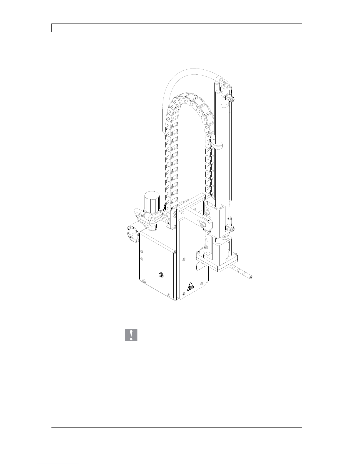
2.1 Safety Marking
1
Figure 1
CAUTION!
There is a risk of injury due to the movement of the pad
downwards and back up again.
Do not reach into the working area of the pad.
Keep hair, loose clothing and items of jewellery out of
this area.
When incorporating the unit into the overall system,
safety precautions must be taken so that no-one is
able to reach into the working area.
1 = Risk of crushing due to
1 = the movement of the pad

Applicator APL 100 Safety Instructions
11/13 Operating Manual 9
2.2 Operating Conditions
Before initial operation and during operation these operating
conditions have to be observed to guarantee save and interferencefree service of our printers.
Therefore please carefully read these operating conditions.
Shipment and storage of our printers are only allowed in original
packing.
Installation and initial operation of printer is only allowed if operating
conditions were fulfilled.
Commissioning is prohibited until it can be established that, where
relevant, the machine into which the partly completed machinery is to
be incorporated complies with the provisions of Machinery Directive
2006/42/EC.
Initial operation, programming, operation, cleaning and service of our
printers are only recommended after careful study of our manuals.
Operation of printer is only allowed by especially trained persons.
NOTICE!
Perform trainings regularly.
These indications are also valid for someone else's equipment
supplied by us.
Only use original spare and exchange parts.
CPU of printer is equipped with a lithium battery (type CR 2032) for
which the battery regulation is to apply. This regulation plans that
unloaded batteries have to be given to used battery collecting
containers of trade and public carries. In case that batteries were not
completely discharged you have to make arrangements for shortcircuits. At a shutdown of printer the battery has to be disposed in
either case separately from printer.
DANGER!
Danger of life by explosion!
Use non-conducting tools.
The installation place of printer should be even, free of vibration and
currents of air are to be avoided.
The printers have to be installed to ensure optimal operation and
servicing.
Instructions for
lithium battery
Conditions for
installation place

Safety Instructions Applicator APL 100
10 Operating Manual 11/13
The installation of the power supply to connect our printers has to be
effected according to the international rules and regulations,
especially the recommendations of one of the three following
commissions:
International Electronic Commission (IEC)
European Committee for Electro technical Standardisation
(CENELEC)
Verband Deutscher Elektrotechniker (VDE)
Our printers are constructed according to VDE and have to be
connected to a grounded conductor. The power supply has to be
equipped with a grounded conductor to eliminate internal interfering
voltage.
Power line voltage and power line frequency: See type plate
Allowable tolerance of power line voltage:
+6% to −10% of nominal value
Allowable tolerance of power line frequency:
+2% to −2% of nominal value
Allowable distortion factor of power line voltage: <=5%
In case your net is infected (e.g. by using thyristor controlled
machines) anti-interference measures have to be taken. You can use
one of the following possibilities:
Provide separate power supply to our printers.
In case of problems please connect capacity-decoupled isolation
transformer or similar interference suppressor in front of our
printers.
Emitted interference according to EN 61000-6-3: 2007
industrial sector
Interference voltage to wires according to EN 55022: 09-2003
Interference field power according to EN 55022: 09-2003
System perturbation according to EN 61000-3-2: 09-2006
Flicker according to EN 61000-3-3: 1955 + A1:2001 + A2:2005
Installation of
power supply
Technical data of
power supply
Anti-interference
measures
Stray radiation and
immunity from
disturbance

Applicator APL 100 Safety Instructions
11/13 Operating Manual 11
Immunity to interference according to EN 61000-6-2: 2005
industrial sector
Stray radiation against discharge of static electricity according to
EN 61000-4-2: 12-2001
Electromagnetic fields according to EN 61000-4-3: 11-2003,
ENV 50204: 03-1995
Fast transient burst according to EN 61000-4-4: 07-2005
High-frequency tension according to EN 61000-4-6: 12-2001
NOTICE!
This is a machine of type A. This machine can cause
interferences in residential areas; in this case it can be required
from operator to accomplish appropriate measures and be
responsible for it.
EN 415-2 - Safety of packaging machines
EN 60204-1:2006 - Safety of machinery – Electrical equipment of
machines – Part 1
All connecting lines have to be guided in shielded lines. Shielding has
to be connected on both sides to the corner shell.
It is not allowed to guide lines parallel to power lines. If a parallel
guiding cannot be avoided a distance of at least 0.5 m has to be
observed.
Temperature of lines between: −15 to +80 °C.
It is only allowed to connect devices which fulfil the request 'Safety
Extra Low Voltage' (SELV). These are generally devices which are
checked corresponding to EN 60950.
The data cables must be completely protected and provide with metal
or metallised connector housings. Shielded cables and connectors are
necessary, in order to avoid radiant emittance and receipt of electrical
disturbances.
Allowable lines
Shielded line:
4 x 2 x 0,14 mm² ( 4 x 2 x AWG 26)
6 x 2 x 0,14 mm² ( 6 x 2 x AWG 26)
12 x 2 x 0,14 mm² (12 x 2 x AWG 26)
Sending and receiving lines have to be twisted in pairs.
Maximum line length:
with interface V 24 (RS-232C) - 3 m (with shielding)
with Centronics - 3 m (with shielding)
USB - 5 m
Ethernet - 100 m
Stray radiation and
immunity from
disturbance
Machine safety
Connecting lines to
external machines
Installation of
data lines

Safety Instructions Applicator APL 100
12 Operating Manual 11/13
To avoid inadmissible heating, free air convection has to be ensured.
Protection according IP: 20
Ambient temperature °C (operation): Min. +5 Max. +35
Ambient temperature °C (storage): Min. −25 Max. +60
Relative air humidity % (operation): Max. 80
Relative air humidity % (storage): Max. 80
(bedewing of printers not allowed)
We do not take any responsibility for damage caused by:
Ignoring our operating conditions and operating manual.
Incorrect electric installation of environment.
Building alterations of our printers.
Incorrect programming and operation.
Not performed data protection.
Using of not original spare parts and accessories.
Natural wear and tear.
When (re)installing or programming our printers please control the
new settings by test running and test printing. Herewith you avoid
faulty results, reports and evaluation.
Only specially trained staff is allowed to operate the printers.
Control the correct handling of our products and repeat training.
We do not guarantee that all features described in this manual exist in
all models. Caused by our efforts to continue further development and
improvement, technical data might change without notice.
By further developments or regulations of the country illustrations and
examples shown in the manual can be different from the delivered
model.
Please pay attention to the information about admissible print media
and the notes to the printer maintenance, in order to avoid damages
or premature wear.
We endeavoured to write this manual in an understandable form to
give and you as much as possible information. If you have any queries
or if you discover errors, please inform us to give us the possibility to
correct and improve our manual.
Air convection
Limit values
Guarantee

APL 100 Series Product Description
11/13 Operating Manual 13
3 Product Description
The applicator APL 100 is an optional device to use with label printers
of the Compa or Compa II series for automatically applying the printed
label onto the product. The labels are transferred with a pad, which
moves between the two positions, starting position and labelling
position, by a compressed-air driven pneumatic cylinder.
In the starting position, the label is picked up from the printer.
A sensor at the cylinder signals when the pad is in the starting
position.
The label is removed from the carrier ribbon directly at the
dispense edge of the printer. It is sucked on the pad by a vacuum
via drillings at the bottom of the pad.
For support, the label is also blown against the pad (supporting
air) with an air current coming from a blow tube.
The correct transfer of the label is controlled by a vacuum sensor.
Next, the pad is moved down into the labelling position. Reaching
the labelling position is confirmed by another sensor (labelling
position sensor).
In the labelling position the label is transferred onto the product.
While the pad is moving back into the starting position, the
vacuum sensor checks whether the label has been removed from
the pad.
The label can be applied with three different methods:
Stamp on
The label is pressed directly onto the product.
Blow on
The pad moves to a pre-adjusted position approximately 10 mm away
from the product. The label is blown onto the product by an air stream.
Roll on
In the starting position the label is forwarded until touching the roller of
the roll on pad. At the labelling position the roller is pressed onto the
product. Then the label is applied and rolled on by the movement of
the product.
Application
of the label

Product Description Applicator APL 100
14 Operating Manual 11/13
3.1 Important Characteristics
The supporting air and the vacuum as well as the speed of the
cylinder are adjustable. That way the applicator can be adapted to
different label materials and sizes.
The pressure for the cylinder movement is reduced in relation to
the operating pressure of the entire labelling machine so that the
danger of injury is reduced as much as possible.
To avoid contamination within the vacuum channels they are
cleaned by air pressure impulse at the end of each application.
For integration into a superordinated process the printers are
equipped with 'Dispenser I/O'.
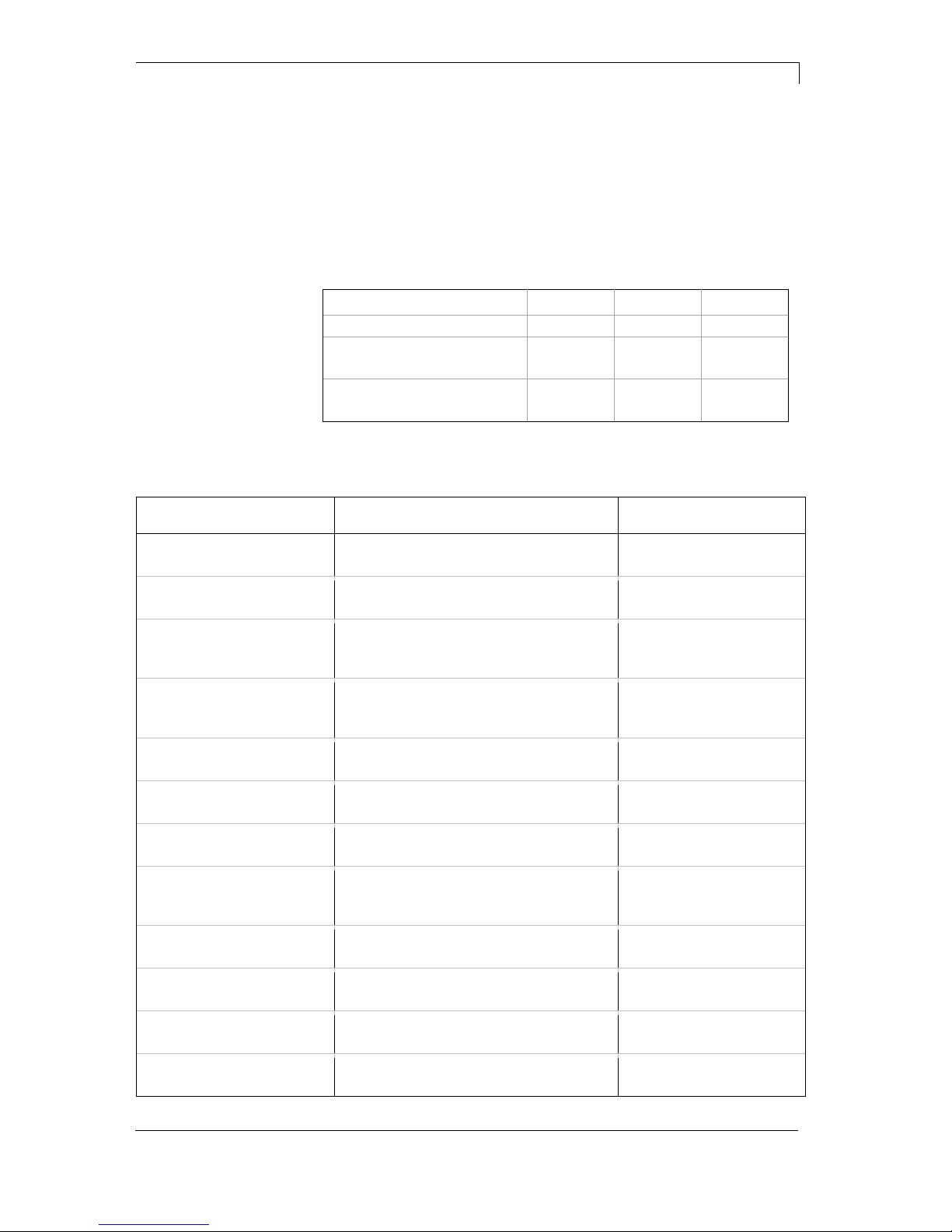
3.2 Technical Data
Label transfer method Stamp on Blow on Roll on
Labe width (mm) 25 - 176 25 - 176 25 - 176
Label height (mm) 25 - 200 25 - 100 80 - 200
Cylinder stroke (mm) 300 300 300
Pad stroke below printer (mm) 180 180 180
Compressed air pressure 5 bar 5 bar 5 bar
Product surface flat flat flat
Product height variable
Product height fixed
Product fixed
Product linear movement
Applicator APL 100 Product Description
11/13 Operating Manual 15
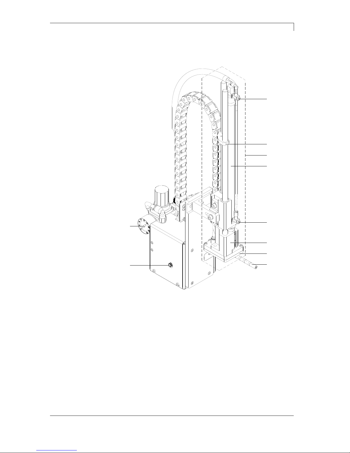
3.3 Device Overview
1
2
3
4
5
6
7
8
10
9
Figure 2
11 = Upper cylinder throttle valve
02 = Stopper for the operation mode 'Blow on'
03 = Cylinder unit
04 = Pneumatic cylinder
05 = Lower cylinder throttle valve
06 = Pad holder
07 = Pad (application specific)
08 = Blow tube for supporting air
09 = Knurled screw for attaching the applicator to the printer
10 = Main pressure manometer
Front view
Product Description Applicator APL 100
16 Operating Manual 11/13
1
2
34
5678910
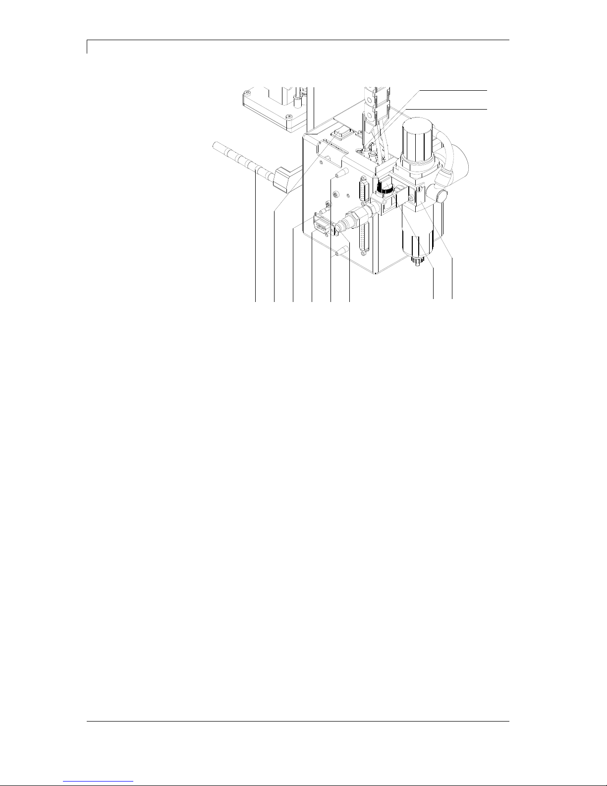
Figure 3
11 = Supporting air throttle valve
02 = Vacuum throttle valve
03 = Service unit
04 = Shutoff valve
05 = Compressed air connector
06 = Pins
07 = Interface to the printer
08 = Knurled screw for attaching the applicator to the printer
09 = Pre-dispense key
10 = Blow tube for supporting air
Rear view
Applicator APL 100 Product Description
11/13 Operating Manual 17
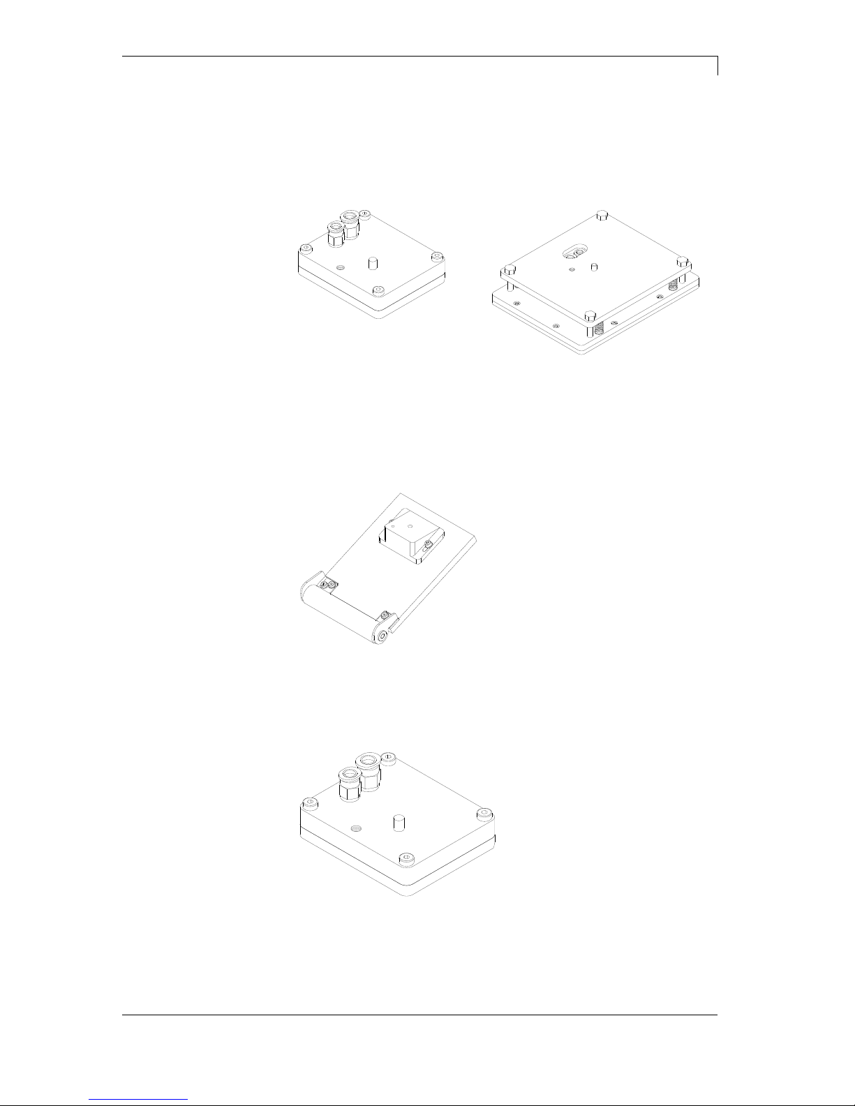
3.4 Pads
Universal tamp pad Universal tamp pad
Standard sizes:
70 x 60 mm and 90 x 90 mm
Standard sizes:
116 x 102 mm and 116 x 152 mm
Figure 4 Figure 5
Universal tamp are available in different standard sizes. According to
the size of the label the holes may be pierced by the customer. For
that purpose a piercing pin is included in the delivery contents.
On request, tamp pads customized to the label sized are delivered.
Figure 6
Roll-on pads are only produced on request customized to the label
size.
Figure 7
Blow pads are only produced on request customized to the label size.
Tamp pads
Roll-on pads
Blow pads


Applicator APL 100 Installation
11/13 Operating Manual 19
4 Installation
4.1 Scope of Delivery
NOTICE!
Please keep the original packaging in case the applicator must
be returned.
1234
Figure 8
1 = Applicator with cylinder
2 = Pad (according to command)
3 = Cylinder screw (part of the pad)
4 = Piercing pin (at universal tamp pads only)
CAUTION!
The label printer and the applicator can be damaged by
moisture and water.
Set up the label printer with applicator only in dry locations
protected from splash water.

Installation Applicator APL 100
20 Operating Manual 11/13
4.2 Mounting the Applicator to the Printer
CAUTION!
Danger of injury by inadvertent move out of the cylinder.
Disconnect the printer from the power supply before
mounting the applicator.
Connect the compressed air only after mounting the
applicator to the printer.
12 34
Figure 9
1. Insert the pins (6, Figure 3) on the back of the applicator (2) into
the holes (3) of the printer.
2. Press the applicator against the printer. That way the plug of the
applicator will be connected to the peripheral port (4) of the
printer.
3. Fix the applicator (2) with the screw (1).
CAUTION!
Malfunctions by inadequate operational surface space.
Ensure a stable standing of the printer.

Applicator APL 100 Installation
11/13 Operating Manual 21
4.3 Piercing the Universal Tamp Pad
On the bottom of the pads there are holes for sucking and holding the
labels by vacuum. When an universal tamp pad is delivered these
holes are covered by the sliding foil and must be opened according to
the label size. For that purpose a piercing pin is included in the
contents of delivery.
2
m
m
123
4
Figure 10
1. Place a label (1) to be operated on the bottom side of the pad (2).
Note the position of the slanted edge (3).
2. Align the label to the side edge in such a way that it reaches over
the rear edge of the pad by 2 mm.
3. Open all the holes, which are certainly covered by the label.
Open the holes completely by turning the piercing pin (4) inside
the holes.
CAUTION!
Malfunctions by a too weak vacuum.
Do not open holes which are located less than 1 mm
from a label edge.

Installation Applicator APL 100
22 Operating Manual 11/13
4.4 Preparing for Using a Sprint-Mounted Tamp Pad
NOTICE!
For using a spring-mounted universal tamp pad (> 90 x 90 mm)
the fitting of the cylinder unit must be changed.
The cylinder unit (6) can be mounted on the bracket (1) in two
different positions.
When the applicator is delivered, the cylinder unit is mounted on the
bracket using the upper threaded hole (4). That position is suitable for
the most pads.
1
2
3
4
5
6
Figure 11
1. Loosen the screw (3) and washer (2).
2. Dismount the cylinder unit (6) from the connecting bracket.
3. Fix the cylinder unit (6) with the screw (3) at the connecting
bracket (1) by using the lower threaded hole (5).

Applicator APL 100 Installation
11/13 Operating Manual 23
4.5 Mounting the Pad
6
7
8
1
2
3
4
5
Figure 12
1. Pull the tube (6) out of the push-in-fitting.
2. Insert the pin (5) on the pad (8) into the hole on the bottom side of
the pad holder (7).
3. Fix the pad (8) with the screw (1) at the pad holder (7) and make a
rough adjustment of the pad to the printer dispense plate.
4. Insert the vacuum tube (2) an the blowing air tube into the
appropriate push-in-fittings (3,4) of the pad.
5. Insert the tube (6) into the appropriate push-in-fitting on the
cylinder.
CAUTION!
Danger of collision of the pad with other parts of the labelling
system.
Before connecting the applicator to the compressed air
supply please roughly align the pad in all directions..

Installation Applicator APL 100
24 Operating Manual 11/13
4.6 Mounting the Stopper
NOTICE!
In the operating modes 'Stamp on' and 'Roll on' the stopper is
not needed.
213
4
3
1
Figure 13
When the applicator is delivered, the stopper (1) is mounted on the
rods (4). With this stopper the labelling position for the operation mode
'Blow on' can be adjusted.
1. Slide the stopper (1) with the rubber buffer (2) down onto the rods.
2. Adjust the stopper (1) (see chapter 7.5, page 37).
In the operating modes 'Stamp on' and 'Roll on' the stopper is not
needed. The stopper may not limit the pad movement.
1. Loosen the screw (3) at the stopper (1).
2. Slide the stopper (1) as far as possible upwards and tighten the
screw (3).
or
3. Remove the stopper (1) upwards from the rods (4).
Operating mode
'Blow on'
Operating modes
'Stamp on' and
'Roll on'

Applicator APL 100 Installation
11/13 Operating Manual 25
4.7 Connections
54321
Figure 14
1. Prepare the printer connections to the power supply and to the
computer (see operating manual of the label printer).
2. Close the shutoff valve (3 / lever at the valve is turned across the
air flow direction).
3. Connect the applicator to the compressed air supply.
The connector (2) for the compressed air supply is located at the
rear of the service unit. The connector is suitable for a 1/4"
coupling plug (1) or a tube with a diameter of 8 mm.
4. The air pressure for operating the applicator is pre-adjusted to
0,5 MPa (5 bar). Check the pressure at the manometer (5) of the
service unit. Correct the adjustment if necessary:
Pull knurled knob (4) up.
Turn knob to tune required operating pressure of 5 bar.
Push knob down.
5. Open the shutoff valve (3 / lever is turned in the air flow direction).
6. Switch on the power supply of the printer.
CAUTION!
The pad will immediately be moved in the starting position.
Danger of crushing to hand and fingers by the moving pad.
Do not reach into the zone of the moving pad.
Keep long hair, loose clothes and jewellery distant
from the zone of the moving pad.
Danger of striking by the moving rods.
Do not reach or bend into the zone of the moving rods.

Applicator APL 100 Configuration
11/13 Operating Manual 27
5 Configuration
The label applicator can be operated in different ways. While the
original process stays the same, the operation mode can be chosen
within the function menu of the connected label printer.
The most important setting is the selection between the operating
modes 'Stamp on', 'Blow on' and 'Roll on'. Additionally the applicator
has different application modes concerning the order of printing and
applying within one labelling cycle.
Stamp on Roll on Blow on
Print-Apply
Apply-Print
Waiting position up
Apply-Print
Waiting position down
5.1 Configuration Parameter
Parameter Meaning Selection
Operating mode Setting of operating mode
Default: Stamp on
Stamp on, Blow on, Roll
on
Mode Setting of application mode
Default: Print-apply
Print-apply
Apply-print
Support delay On Setting of switch-on delay
for supporting air
Default: 0 ms
0 ... 2500 ms
in steps of 10 ms
Support delay Off Setting of switch-off delay
for supporting air
Default: 500 ms
0 ... 2500 ms
in steps of 10 ms
Pressure control Setting of compressed-air control
Default: On
On
Off
Vacuum control Setting of vacuum control
Default: On
On
Off
Blow time Setting of blow time
Default: 100 ms
0 ... 2500 ms
in steps of in 10 ms
Waiting position Waiting position of pad with dispensed
label for 'Blow on + Apply-print'
Default: Up
Up
Down
Roll on time Setting of roll on time
Default: 0 ms
0 ... 5000 ms
in steps of 10 ms
Cleaning time Setting of cleaning time
Default: 100 ms
0 ... 2500 ms
in steps of 10 ms
Timeout hub Moving up/down of pad
Default: 0 ms
0 ...5000 ms
in steps of 10 ms
Pressure time Setting of pressure time
Default: 100 ms
0 ...5000 ms
in steps of 10 ms

Configuration Applicator APL 100
28 Operating Manual 11/13
5.2 Settings in printer function menu
Switch on the label printer and the display shows the main menu.
Press key
to access the function menu.
Press key
as long as you arrive the Label applicator menu.
Press key
to select the menu.
Press key
to change to the next mode.
Stamp on:
The label remains in a fixed position. The label is pressed directly onto
the product.
Blow on:
The pad moves to a pre-adjusted position approximately 10 mm away
from the product. The label is blown onto the product by an air jet
stream. The print and apply cycle performs in a fixed position or in
linear movement of the product.
Roll on:
The label is dispensed and moved until touching the roller of the roll
on pad. In the labelling position, this roll is pressed onto the product.
Then the label is applied and rolled on by the movement of product.
Press key
to arrive the next parameter.
The applicator can be operated in two different ways concerning the
order of printing and labelling within one labelling cycle (see chapter 6,
page 32).
Print-Apply:
The print of a label is released by an external start signal. At the same
time the vacuum on the pad as well as the supporting air from the
blow tube are switched on. If the label is printed and picked up
completely from tamp, the supporting air is switched off and the lift
cylinder is controlled to move the pad down towards the labelling
position. A sensor signals when the labelling position is reached.
Following, the vacuum is switched off and the label is transferred to
the product. After applying the label, the lift cylinder is so controlled
that the pad is again moved back to the starting position.
Now the labelling cycle is finished.
Apply-Print:
Before starting the cyclic operation 'apply-print', the printing and
picking up of the first label has to be released separately by a special
signal.
The pad with the printed label is in starting position and the vacuum at
the pad is switched on.
At start of the cyclic operation when sending the start signal, the first
label is already on the pad. The following process is similar to the
mode 'print-apply' but at the end of the cycle the next label is printed
and picked up by the pad.
Now the labelling cycle is finished.
Operating modes
Application mode

Applicator APL 100 Configuration
11/13 Operating Manual 29
Press key
to arrive the next parameter.
The supporting air from the blow tube is not immediately switched on
at print start but only if the label has covered a distance.
This delay helps to prevent a turning or swinging at the front of the
label and consequently avoids faults when the label is being picked up
from printer.
Value range: 0 to 2500 ms
Step size: 0 ms
Default: 0 ms
Press key
to arrive the next parameter.
Delayed to the process of the label being picked up, the supporting air
is switched off.
In many cases, after being picked up by the pad the label edge may
still stick on the liner. This may affect the accuracy of the label
positioning or even cause faults in the labelling. Therefore, switching
off the air blow delayed can be useful to separate the label from liner
and neatly place the label on the surface of pad.
Value range: 0 to 2500 ms
Step size: 10 ms
Default: 500 ms
Press key
to arrive the next parameter.
With activated compressed air control, with help from a compressed
air sensor it is checked at each labelling cycle if the compressed air
fits with the valve block. If no compressed air is presented, the
labelling cycle is stopped and the error message 'compressed air' is
displayed.
If the parameter 'pressure control' is set to Off, the error treatment as
described above will not be effected. This can be especially helpful at
initiation of the labelling system.
For standard operation, set the parameter to On.
Press key
to arrive the next parameter.
The label transfer from printer to applicator is controlled by a vacuum
sensor. If the transfer of label fails, the sucking holes on the pad will
not be covered by the label and therefore no vacuum can originate on
the pad. Afterwards an error message appears and the label strip will
be fed back.
If the parameter 'vacuum control' is set to Off, the error treatment as
described above will not be effected. This can be especially helpful
during adjustments, because the immediate backfeed will be
cancelled and therefore it is easier to check the reasons for the faulty
transfer.
For standard operation, set the parameter to On.
Support delay On
Support delay Off
Pressure control
Vacuum control

Configuration Applicator APL 100
30 Operating Manual 11/13
Press key
to arrive the next parameter.
This parameter is only active if the operating mode 'blow on' is
selected. The time period can be adjusted, while the blowing air is
switched on for transferring the label onto product.
Value range: 0 to 2500 ms
Step size: 10 ms
Default: 100 ms
Press key
to arrive the next parameter.
NOTICE!
This parameter is only active if the operating mode 'blow on'
and mode 'apply-print' are selected.
Waiting position up:
In cyclic mode the pad with the printed label waits in the labelling
position near the dispense edge of printer for the external start signal.
Waiting position down:
In cyclic mode the printed label is transported to the labelling position
at the end of a cycle.
So the next cycle begin with blowing up the label.
Press key
to arrive the next parameter.
This parameter is only active if the operating mode 'blow on' is
selected. The time period can be adjusted while the roll on pad is
stopped in labelling position.
Value range: 0 to 5000 ms
Step size: 10 ms
Default: 0 ms
Press key
to arrive the next parameter.
This parameter is only active if the operating mode 'blow on' and 'roll
on' are selected. The time period can be adjusted for the cleaning
period of pad after application procedure.
Value range: 0 to 2500 ms
Step size: 10 ms
Default: 100 ms
Press key to arrive the next parameter.
Moving up and down of pad.
If the pad does not reach the corresponding final position within the
set time, then an error message appears ('final position above' at
moving up and/or 'final position below' at moving down).
Value range: 0 to 5000 ms
Step size: 10 ms
Default: 0 ms
Blow time
Waiting position
Roll on time
Cleaning time
Stroke timeout

Applicator APL 100 Configuration
11/13 Operating Manual 31
Press key
to arrive the next parameter.
This menu serves for the applicator setup as well as for error tracing.
Input signals of the applicator can be monitored and output signals
can be set or reset separately. With keys
and the
corresponding output for setting and/or resetting the output signals
can be selected. With keys
and the corresponding output can
be set or reset.
Input signals
I1 = Pre-dispense key (1 = key pressed, 0 = key not pressed)
I2 = Final position up (1 = pad in final position up,
0 = pad not in final position up)
I3 = Final position down (1 = pad in final position down,
0 = pad not in final position down)
I4 = Compressed air (1 = compressed air available,
0 = no compressed air available)
I5 = Vacuum (1 = vacuum at pad available, 0 = no vacuum at pad
available)
Output signals
1 = Move pad downwards (1 = On, 0 = Off)
2 = Move pad upwards (1 = On, 0 = Off)
3 = not assigned
4 = not assigned
5 = Blowing air (1 = On, 0 = Off)
6 = Supporting air (1 = On, 0 = Off)
7 = Vacuum pad (1 = On, 0 = Off)
Press key
to arrive the next parameter.
This parameter is only active if the operating mode 'stamp on' is
selected. The time period can be adjusted while the pad is kept in the
labelling position for applying the label onto the goods.
Input/Output
Pressure time

Signal Diagrams Applicator APL 100
32 Operating Manual 11/13
6 Signal Diagrams
6.1 Print - Apply
Input: Print start
Print process
Supporting air
Output: Label print
Vacuum
Pad
Delay On Delay Off
Apply
Blow on
Cleaning time
Figure 15
6.2 Apply - Print
Figure 16

Applicator APL 100 Mechanical Adjustments
11/13 Operating Manual 33
7 Mechanical Adjustments
NOTICE!
Perform the mechanical adjustments in two steps
Roughly align the pad in all directions to avoid collisions
of the pad with other parts when switching on the
compressed air.
Perform the fine adjustment with compressed air
switched on to optimize the labelling process.
7.1 Aligning the pad
2
1
3
2
1
4
5
Figure 17
1. Loosen screw (3).
2. Shift the cylinder unit including the pad (4) inside the elongated
hole in such a way, that the distance between the pad and the
dispense edge (5) is about 2 mm.
3. Tighten screw (3).
1. Loosen screw (1).
2. Shift the cylinder including the pad (4) inside the elongated hole in
such a way that the lower rear edge of the pad (4) is located about
1 mm below the dispense edge (5) of the printer.
3. Tighten screw (1).
Adjustment in
print direction
Height adjustment

Mechanical Adjustments Applicator APL 100
34 Operating Manual 11/13
1. Loosen screw (2).
2. Shift the cylinder unit including the pad (4) inside the elongated
hole in such a way, that the dispensed label is aligned centrally to
the pad respectively to the open holes in an universal pad.
3. Tighten screw (2).
NOTICE!
Check the adjustment with compressed air switched on.
7.2 Adjusting the Parallelism between Pad and
Dispense Edge
123
Figure 18
1. Loosen screw (1).
2. Adjust the parallelism between the rear edge of the pad (2) and
the dispense edge (3) by turning the pad.
3. Tighten screw (1).
Side adjustment

Applicator APL 100 Mechanical Adjustments
11/13 Operating Manual 35
7.3 Opening the Holes on the Blow Tube
123
Figure 19
1. The blow tube (1) has holes for the supporting air in regular
distances of 15 mm.
2. When the applicator is delivered only the two inner holes are
open. The other holes are closed by plastic rings (3).
3. To adjust the supporting air to the label width, the plastic rings (2)
can be removed from the holes.
4. Open all holes, which affect certainly the area of the label.

Mechanical Adjustments Applicator APL 100
36 Operating Manual 11/13
7.4 Aligning the Blow Tube
21
Figure 20
The blow tube (2) for the supporting air can be rotated around its axis.
That way the direction of the supporting air can be optimized.
1. Loosen screw (1).
2. Turn the blow tube (2) in that direction that the air current supports
the sucking of the label by the pad.
234
Figure 21
For small labels direct the air current to the dispense edge (3) of
the printer (setting 3 or 4 at the scale).
For larger labels direct the air current away from the dispense
edge (3 / setting 1).
3. Tighten screw (1).

Applicator APL 100 Mechanical Adjustments
11/13 Operating Manual 37
7.5 Adjusting the Stopper
NOTICE!
For operating mode 'Blow on' only.
3
2
1
4
5
6
7
Figure 22
CAUTION!
Danger of injury by inadvertent move out of the cylinder.
Switch off the printer and close the shutoff valve for
the compressed air at the service unit.
1. Place a product sample (7) at the labelling point.
2. Pull the tubes out of the push-in-fittings (1,5).
3. Loosen the screw (3) in the stopper (2).
4. Move the pad manually in the required labelling position. The
distance between the blow pad (6) in the labelling position and the
product surface (7) must not exceed 10 mm.
5. Move the stopper (2) against the guide block (4) and tighten the
screw (3).
6. Insert the tubes into the appropriate push-in-fittings (1,5).
7. Open the shutoff valve and switch on the printer.


Applicator APL 100 Pneumatic Adjustments
11/13 Operating Manual 39
8 Pneumatic Adjustments
8.1 Control Valves
3
4
5
121 67891011
Figure 23
For adjustments of certain applicator functions it is possible to release
the control valves in the pneumatic system.
Loosen screws (1) and remove cover (2).
The compressed air control valves can be controlled manually
with integrated switch.
3-way valve (3) to control the lift cylinder
If the printer is switched on the valve will controlled by electronics and
the tamp will hold in the upper end position (home position). If the
valve switched the tamp will move in the lower end position (labelling
position).
In normal labelling operation the movement back in the upper end
position will start by a signal from labelling sensor.
NOTICE!
The switching by hand of this valve has only a result in case of
a switched off printer.
Switching the valve by hand over switch 7 the tamp will move down up
to the lowest possible position because no control is made by the
sensor.
Switching the valve by hand over switch 7 the tamp will move up.

Pneumatic Adjustments Applicator APL 100
40 Operating Manual 11/13
3
4
5
121 67891011
Figure 24
Double 2-way valve (4) for blow air
In the operation mode 'Blow on' the label will blow up to the product.
In the operating modes 'Stamp on' and 'Roll on' the blow air is
switched on for a short time after each application to avoid
contaminations within the vacuum channels.
For all described functions both valves will be controlled parallel.
By pressing the keys 8 or 9 the blow air is only switched on by one of
both internal valves.
Double 2-way valve (5) for vacuum / supporting air
The two internal valves serve the vacuum nozzle for connecting an in
this way for creating the negative pressure at the tamp and
independent of this for connecting the support air at the blow tube for
the label transfer.
By pressing switch 10 the vacuum is switched on and by pressing
switch 11 the supporting air is switched on.

Applicator APL 100 Pneumatic Adjustments
11/13 Operating Manual 41
8.2 Adjusting the Pad Movement Speed
1
2
3
4
Figure 25
The adjustment of pad movement speed can be regulated with two
throttle valves (1, 3).
Adjust the pad movement speed as necessary.
To increase the downward speed turn the screw (4) at the lower
valve (3) anticlockwise.
To increase the upward speed turn the screw (2) at the upper
valve (1) anticlockwise.
NOTICE!
The application pressure of the pad is mainly dependent on
the downward speed of the pad.
To reduce the application pressure turn screw (4) in
clockwise direction.
CAUTION!
A too high decrease of the downward speed leads to an
error message (Error 101 - Lower position).
The downward movement may not need more time as
specified in the menu Timeout Hub (see page 30).

Pneumatic Adjustments Applicator APL 100
42 Operating Manual 11/13
8.3 Adjusting Vacuum and Supporting Air
1
2
Figure 26
Adjusting the supporting air
With the valve (1) the supporting air for blowing the label to the pad
can be varied.
Adjust the supporting air in such way that the label is blown on
the pad without swirling.
To increase the supporting air turn the screw at the valve (1)
anticlockwise.
If necessary adjust the direction of the air current (see chapter
Aligning the Blow Tube, page 36).
Adjusting the vacuum
NOTICE!
With the vacuum setting the final position of the label on the
pad can be adjusted. If the vacuum is too high the label
feeding may early be stopped.
With the valve (2) the vacuum for sucking the label to the pad can be
varied.
Adjust the vacuum in such way that the label is correctly sucked.
To increase the vacuum turn the screw at the valve (2)
anticlockwise.
Applicator APL 100 Operation
11/13 Operating Manual 43
9 Operation
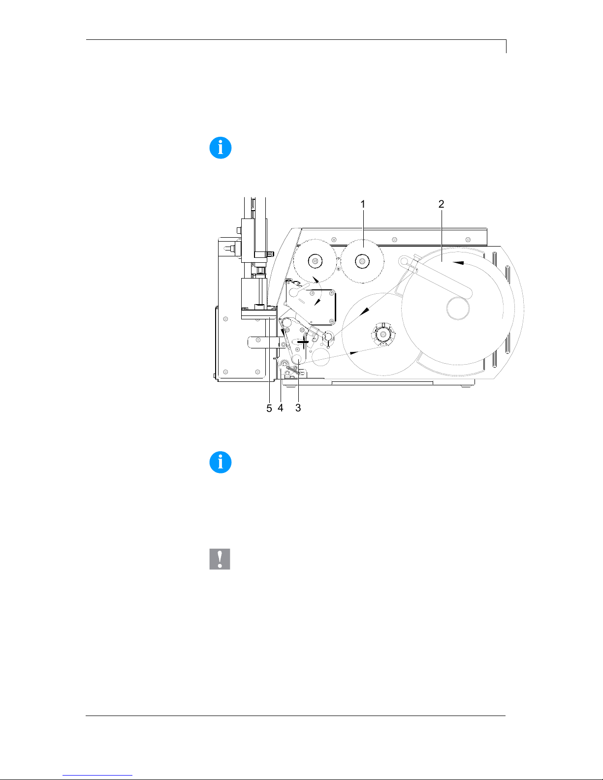
9.1 Loading the Label Material
NOTICE!
In dispensing mode the labels are removed after printing, and
only the liner is wound up internally.
3
1
2
4
5
Figure 27
NOTICE!
For detailed information about inserting the material please
read the operating manual of the label printer.
Insert the transfer ribbon (1).
Insert the label material.
CAUTION!
Collision between the pad (5) and the locking system (4)
during the labelling procedure.
Swivel the locking system (4) on the rewind assistant
roller (3).

Operation Applicator APL 100
44 Operating Manual 11/13
9.2 Setting the Dispenser Mode
NOTICE!
To operate the label printer in dispenser mode a print order
must be started and the printer is to be in 'waiting' mode.
Switch on the label printer and the display shows the main menu.
Press key
to access the function menu.
Press key
as long as you arrive the Dispenser I/O menu.
Press key
to select the menu.
In the upper line of display, the operating mode can be selected.
In the line below, the dispenser I/O offset (approx. 18 mm) can be set.
Press key
to change to the next operating mode.
Off:
It is printed without the labels are dispensed.
I/O static:
The input signal evaluated, i.e. it is printed as long as the signal
exists. The number of labels which was entered at the print start is
printed.
The set dispenser offset is not taken into consideration.
I/O static continuous:
For description of this operating mode, see I/O static.
Continuous means that it is printed as long as new data is transferred
via interface
The set dispenser offset is not taken into consideration.
I/O dynamic:
The external signal is evaluated dynamically, i.e. is the printer in
'waiting' mode a single label is printed at each signal changing. After
the print the set dispenser offset is executed, i.e. a backfeed is
effected.
I/O dynamic continuous:
For description of this operating mode, see I/O dynamic.
Continuous means that it is printed as long as new data is transferred
via interface.
Photocell:
The printer is controlled via photocell. The printer prints automatically
a label if the user takes away the label at the dispensing ledge. The
print order is finished when the target number of labels is reached.
Photocell continuous:
For description of this operating mode, see Photocell.
Continuous means that it is printed as long as new data is transferred
via interface.
Operating modes

Applicator APL 100 Operation
11/13 Operating Manual 45
9.3 Test Mode
Test Mode Using the Pre-dispense Key without Print Job
1
Figure 28
The whole labelling process can be simulated without the need of a
print job or a connection to a computer by pressing the key
and
the pre-dispense key (1).
Press the key .
A blank label is fed. The vacuum at the pad as well as the
supporting air (blow tube) are switched on.
After the label has been picked up by the pad, the supporting air
is switched off.
Press the pre-dispense key (1).
The pad is moved to the labelling position. A sensor signals
when the labelling position is reached. The vacuum is switched
off and the label is placed onto the product. Then the pad is
moved back into the starting position.
NOTICE!
Please use this method to find the appropriate dispenser
offset in the printer configuration.

Operation Applicator APL 100
46 Operating Manual 11/13
Test Mode Using the Pre-dispense Key without Print Job
This method allows to check the labelling process with real print data
using the pre-dispense key (1, Figure 28).
Send a print job.
The test mode is executed in two half-cycles.
Press the pre-dispense key (1, Figure 28).
Half-cycle 1
A label is printed. The vacuum at the pad as well as the
supporting air (blow tube) are switched on. After the label has
been picked up by the pad, the supporting air is switched off.
Press the pre-dispense key (1, Figure 28) again.
Half-cycle 2
The pad is moved to the labelling position. A sensor signals
when the labelling position is reached. The vacuum is switched
off and the label is placed onto the product. Then, the pad is
moved back into the starting position.
If the label is manually removed from the pad after the first half cycle,
the half cycle 1 will be repeated when the pre-dispense key is pressed
again.
NOTICE!
Please use this method to adjust the appropriate dispenser
offset in the label design software.

Applicator APL 100 Operation
11/13 Operating Manual 47
9.4 Standard Operation
1. Check all external connections (see chapter 4.7, page 25).
2. Load the transfer ribbon and the label material (see chapter 9.1,
page 43).
NOTICE!
Ensure that the locking system (4, Figure 27) is closed.
3. Open the shutoff valve.
CAUTION!
If the pad is covered the vacuum sensor may be
calibrated faultily.
Before switching on the printer-applicator system
ensure that the pad is not covered.
4. Switch on the label printer.
CAUTION!
The pad will immediately be moved in the starting
position.
Do not reach into the zone of the moving pad.
Keep long hair, loose clothes and jewellery distant.
Do not reach or bend into the zone of the moving
rods.
5. Press the key
at the printer.
A synchronization feed is released. The processed labels have to
be removed manually. After a few seconds the printer carries out
a short backfeed to position the front edge of the next label at the
printing line.
NOTICE!
This synchronizing also has to be carried out when the print
job has been interrupted with the key
.
Synchronizing is not necessary when the printhead was not
lifted between print jobs. This also applies if the printer was
powered off between print jobs.
6. Start a print job.


Applicator APL 100 Applicator Interface
11/13 Operating Manual 49
10 Applicator Interface
10.1 Pin Assignment
Figure 29
10.2 Internal Circuit of Outputs
Figure 30
The outputs are realized by optocouplers.
With an active signal the collector emitter line of the optopoupler is
conductive.

Applicator Interface Applicator APL 100
50 Operating Manual 11/13
10.3 Signal Assignment D-Sub 15 pin
D-Sub 15 pin female connector APL 100
Pin Signal Description Active state
9
Collector signal
Upper final
position
Tamp pad is in the final
position in which the
transfer of label from the
printer can be done
Collector
emitter line
conductive
1
Emitter signal
Lower final
position
10
Collector signal
Lower final
position
Tamp pad is in the final
position in which the
transfer of label to the good
can be done.
Collector
emitter line
conductive
2
Emitter signal
Lower final
position
11
Emitter signal
Compressed-air
Control of the applicators'
compressed-air supply
Collector
emitter line
blocked
3
Emitter signal
Compressed-air
15 24V
Operating voltage
+24V/100 mA made
available by the applicator
8 GND GND connection

Applicator APL 100 Error Messages
11/13 Operating Manual 51
11 Error Messages
11.1 Error Messages of the Printer
In case an error occurred the printer stops and the print order is
interrupted. Information to causes and remedies of printer errors e.g.
no label found are to be taken from the printer manual.
1. Clear the error.
2. Press the key
to synchronize the label feed.
3. Remove the peeled labels manually.
4. Press the key
to quit the error state.
5. Press the key
to continue the print order or press key
to cancel the print order.
11.2 Error Messages of the Applicator
Error message Cause Remedy
Upper position
The upper position (start position)
was not reached.
Check final position switch for start
position and compressed-air supply.
Adjust stroke timeout.
Lower position
The lower position (labelling
position) was not reached.
Check final position switch for labelling
position and compressed-air supply.
Adjust stroke timeout.
Empty vacuum
plate
Sensor does not recognize a label at
the vacuum plate.
Check if all holes of the pad plate are
covered from the label.
Check compressed-air supply.
Print position
At print start the pad is not in printing
position (upper pad position).
Check the correct function and position
of the final position switch for the upper
position (start position).
Check the pneumati function.
CAUTION!
The pad will immediately be moved in the starting position.
Danger of crushing to hand and fingers by the moving pad.
Do not reach into the zone of the moving pad.
Keep long hair, loose clothes and jewellery distant from
the zone of the moving pad.
Danger of striking by the moving rods.
Do not reach or bend into the zone of the moving rods.
After error correction, the print of the label causing the error cannot be
repeated without re-start of the print order.


Applicator APL 100 Declaration
11/13 Operating Manual 53
12 Declaration
12.1 Extended Declaration

Declaration Applicator APL 100
54 Operating Manual 11/13
12.2 EC-Declaration of Conformity

Applicator APL 100 Index
11/13 Operating Manual 55
13 Index
B
Blow tube, adjusting ........................................................................... 36
C
Circuit output, internal ........................................................................ 49
Configuration
Operating mode .............................................................................. 27
Parameter ....................................................................................... 27
Connections ....................................................................................... 25
Control valves ............................................................................... 39, 40
D
Declaration ................................................................................... 53, 54
Device overview
Front view ....................................................................................... 15
Rear view ........................................................................................ 16
Dispenser mode ................................................................................. 44
D-Sub 15 pin, signal assignment ....................................................... 50
E
EC Declaration of conformity.............................................................. 54
Environmentally-friendly disposal ......................................................... 6
Error messages
Applicator ........................................................................................ 51
Printer ............................................................................................. 51
Extended declaration .......................................................................... 53
F
Function menu (printer)
Application modes .......................................................................... 28
Blow time ........................................................................................ 30
Cleaning time .................................................................................. 30
Input/Output .................................................................................... 31
Operating modes ............................................................................ 28
Pressure control .............................................................................. 29
Pressure time .................................................................................. 30
Roll on time ..................................................................................... 30
Stroke timeout ................................................................................. 30
Support delay Off ............................................................................ 29
Support delay On ............................................................................ 29
Test functions ................................................................................. 31
Vacuum control ............................................................................... 29
Vacuum delay ................................................................................. 29
Waiting position .............................................................................. 30
H
Holes (blow tube), opening ................................................................. 35
I
Instructions ........................................................................................... 5
Intended use ......................................................................................... 5
Interface, applicator ............................................................................ 49

Index Applicator APL 100
56 Operating Manual 11/13
L
Label application ................................................................................ 13
Label material, loading ....................................................................... 43
M
Mounting to printer ............................................................................. 20
O
Operating conditions .......................................................... 9, 10, 11, 12
Output circuit, internal ........................................................................ 49
P
Pad
Adjusting ......................................................................................... 34
Mounting ......................................................................................... 23
Movement speed ............................................................................ 41
Pad, aligning
Height adjustment ........................................................................... 33
In print direction .............................................................................. 33
Side adjustment .............................................................................. 34
Pads, models
Blow pad ......................................................................................... 17
Roll-on pad ..................................................................................... 17
Tamp pad ........................................................................................ 17
Pin assignment ................................................................................... 49
Pre-dispense key .......................................................................... 45, 46
Product description ............................................................................. 13
S
Safety instructions ................................................................................ 7
Safety marking ..................................................................................... 8
Scope of delivery ................................................................................ 19
Signal assignment, D-Sub 15 pin ....................................................... 50
Signal diagrams
Apply-Print ...................................................................................... 32
Print-Apply ...................................................................................... 32
Standard operation ............................................................................. 47
Stopper
Adjusting ......................................................................................... 37
Mounting ......................................................................................... 24
Supporting air, adjusting ..................................................................... 42
T
Technical data .................................................................................... 14
Test mode..................................................................................... 45, 46
U
Universal tamp pad
Piercing (standard tamp pad) ......................................................... 21
Preparing (spring-mounted tamp pad) ............................................ 22
V
Vacuum, adjusting .............................................................................. 42


Carl Valentin GmbH
Neckarstraße 78 – 86 u. 94 . 78056 Villingen-Schwenningen
Phone +49 (0)7720 9712-0 . Fax +49 (0)7720 9712-9901
info@carl-valentin.de . www.carl-valentin.de
 Loading...