

Page 1
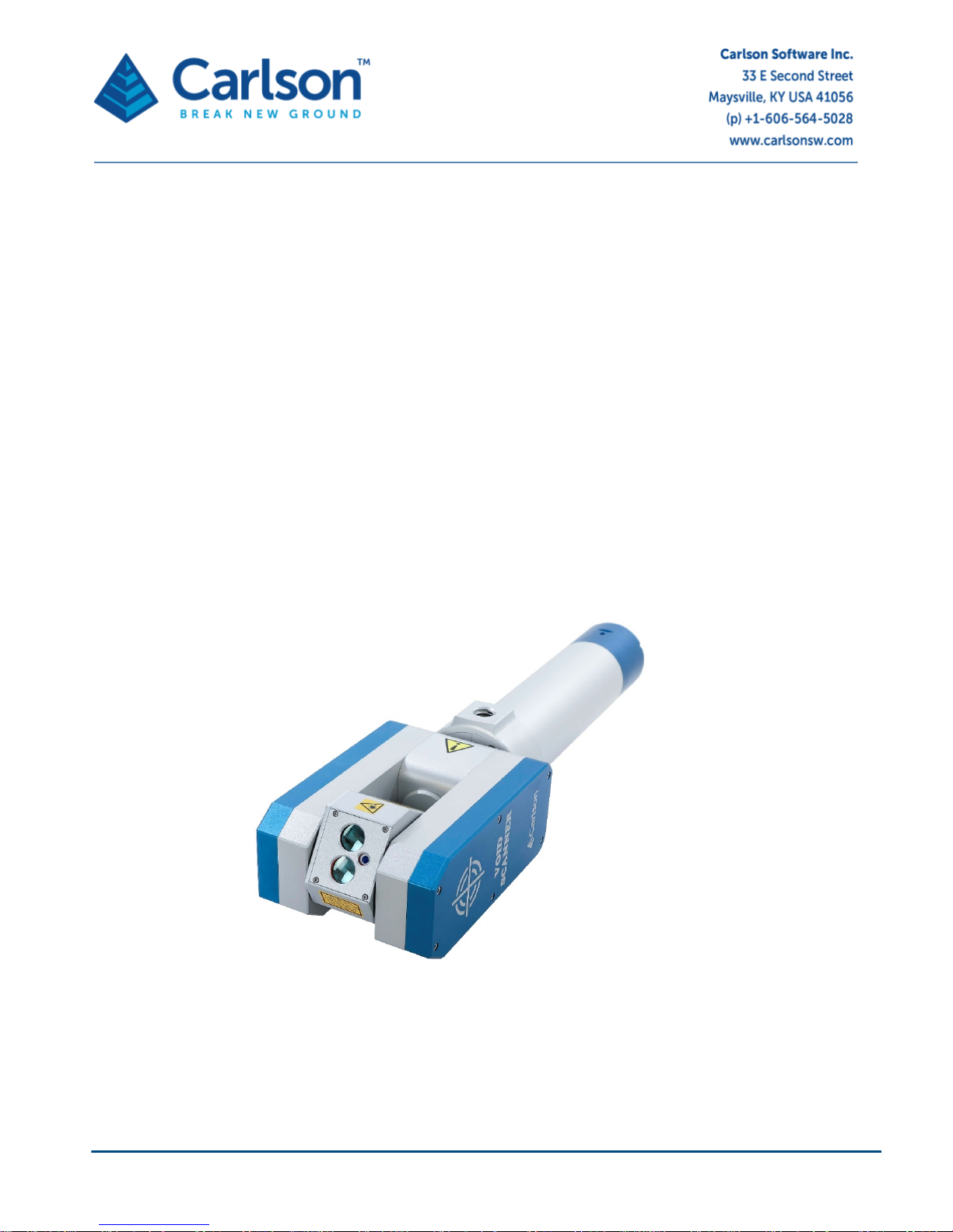
Void Scanner user manual H-5914-8501-03-A September 2018
Void Scanner
underground void surv eying system
user ma nual
Page 2

Page 3

Page | 3
Contents
1 Customer information ............................................................................................................................................................................. 4
1.1 Dear customer ............................................................................................................................................................................. 4
1.2 User manual ................................................................................................................................................................................ 4
2 Laser safety ........................................................................................................................................................................................... 5
2.1 Void Scanner laser module with red dot laser pointer ................................................................................................................... 5
3 Void Scanner system ............................................................................................................................................................................. 6
3.1 System overview .......................................................................................................................................................................... 6
4 Void Scanner hardware .......................................................................................................................................................................... 7
4.1 Void Scanner Probe ..................................................................................................................................................................... 7
4.2 Interface box .............................................................................................................................................................................. 10
4.3 Data cable ................................................................................................................................................................................. 11
4.4 Battery pack ............................................................................................................................................................................... 12
4.5 Alternative external power connections ...................................................................................................................................... 13
4.6 Main Void Scanner cable ........................................................................................................................................................... 13
4.7 Boom adaptor and spigot ........................................................................................................................................................... 14
4.8 Prisms........................................................................................................................................................................................ 15
4.9 Transit case ............................................................................................................................................................................... 15
4.10 Void Scanner Wi-Fi box ............................................................................................................................................................. 16
4.11 Booms and deployment devices................................................................................................................................................. 17
5 Maintenance and care of the Void Scanner ........................................................................................................................................... 19
5.1 General ...................................................................................................................................................................................... 19
5.2 In use ......................................................................................................................................................................................... 19
5.3 Cleaning the Void Scanner......................................................................................................................................................... 19
5.4 Storage and transportation ......................................................................................................................................................... 20
6 Cavity Profiler – VS software................................................................................................................................................................ 21
7 Void Scanner Specifications................................................................................................................................................................. 22
8 Product information .............................................................................................................................................................................. 24
Page 4

Page | 4
1 Customer information
1.1 Dear customer
The Void Scann er s ystem is designed to be eas y to oper ate. Ho we ver, we woul d ask you to tak e the tim e to read
these operating instruction s carefully before using the system, and to k eep the manual with t he instrument at all
times.
For any feedback or c omments, or if there are questions about the Void Scanner s ystem which are beyond the
scope of this manual, contact the product support department at Carlson, or your local Carlson representative.
Alternatively, for information on your local Carlson Software-approved service centre, visit our website at
www.carlsonsw.com.
To ensure best service, please make a note of the serial number. This can be found on a label on the instrument.
1.2 User manual
It is important that you read this manual carefully before using the instrument.
There are three manuals available with the Void Scanner system:
1. This Void Scanner hardware manual which describes the Void Scanner probe and all accessories supplied
with a standard system;
2. A Cavity Profiler – VS software and operations manual;
3. A manual for the Void Scanner Wi-Fi box which is an optional accessory.
It is essential that the accompanying Cavity Profiler – VS software and operations manual is also read and
understood. As we ll as des cribin g the sof t ware, t hat m anual gives a br ief overvie w of a t ypical deplo yment . Som e
troubleshooting guidelines are also offered which ad dress the most common problem s and questions that arise
from users of the Void Scanner.
This manual has been compil ed with care. Howe ver, should you discover a ny errors, we would be gr ateful if you
could contact Carlson directly.
Reproduction in whole or i n part, including utilisat ion in machines c apable of repr oduction or retrie val, wit hout the
express written permission of Carlson is prohibited. Reverse engineering is also prohibited.
The information in this document is subject to change without notice.
Page 5
Page | 5
2 Laser safety
The Void Scanner is supplied with the standard laser module described below which has an integrated red dot laser
pointer.
2.1 Void Scanner laser module with red dot laser pointer
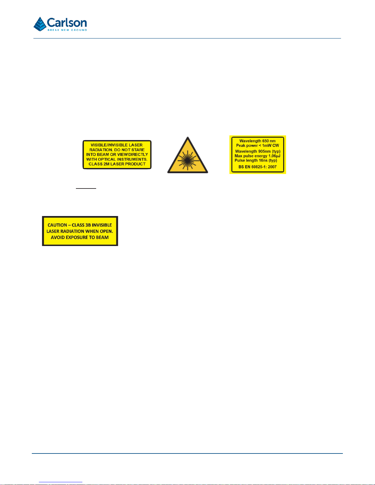
The laser classification of the Void Scanner is a Class 2M laser product in compliance with the British and European
standards for the safety of laser products BS EN 60825-1: 2007.
WARNING: invisible and visible laser radiation. Do not star e into the beam or direct it into the eyes of others.
Do not view directly with optical instruments, e.g. binoculars, theodolite or telescope.
CAUTION: use of controls or adjustments or performance of procedures other that those specified herein
may result in hazardous radiation exposure.
WARNING: opening the protective housing may result in exposure to Class
3B radiation.
All the laser safety labels are located upon the laser module head.
Only qualified and traine d persons should be ass igned to operate the Void Sc anner. When not in use, the las er
should be stored in a location where unauthorized personnel cannot gain access.
We recommend that the i nstrument is not directly pointed at peop le’s eyes, especially if they are using op tical
instruments. Do not unnecessarily look into the transmitter lens of the Void Scanner laser scanner.
Eye protection, desig ned to provide adequate protection against specific laser wav elengths (905 nm typically),
should be used in all hazard areas. Any exceptions should only be undertaken with the approval of the laser safety
officer. All laser protective eyewear shall be clearly labelled with information adequate to ensure proper choice with
the particular laser. For the Void Scanner instrument, the recommended CE marked laser eyewear shall be marked
as “R 905 L1” as specified to EN 207, or equivalent. Note that protection shall be afforded to infrared laser radiation,
and not the visible laser radiation. The visible laser is however Class 2 when operated by itself and as such is s afe
to use without eyewear (unless deliberately stared at).
Page 6
Page | 6
3 Void Scanner system
3.1 System overview
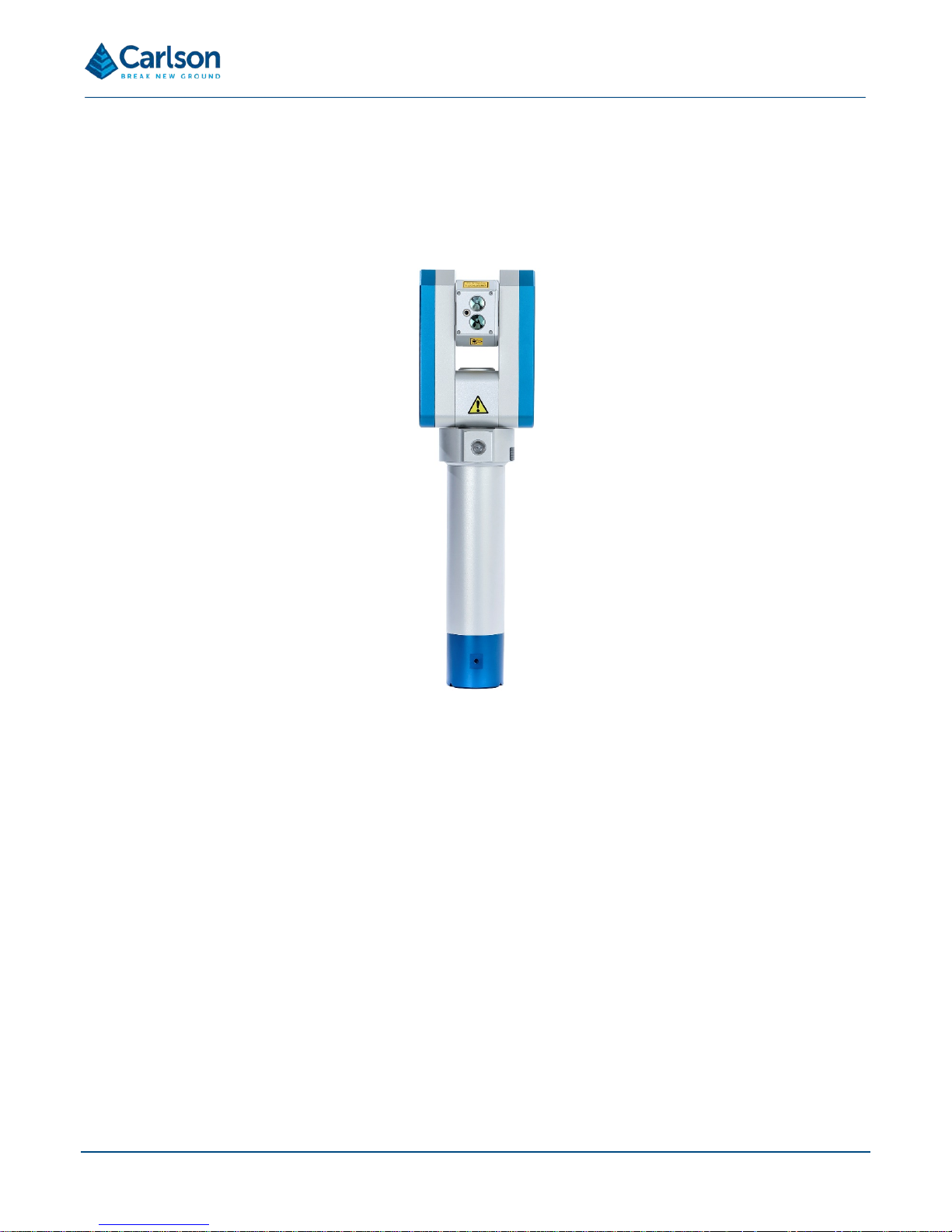
The Void Scanner is a ruggedised field instrument designed to produce fast, efficient 3D laser scans of underground
voids where access is limited, dangerous or prohibited. The instrument can be mounted on booms, tripods or usercustomised deployment devices. The small, lightweight size of the Void Scanner gives flexibility in the nature of the
deployment and m eans that volumes and dimensions which have previous ly been guessed or estimated can be
accurately quantified.
The Void Scanner’s laser em plo ys the ‘tim e of flight’ techniq ue to m easur e ranges to rock fac es and other obj ec ts
without the need to place reflectors on the target. This allows measurements to be taken from a safe distance. Two
hundred such measurements are made every second, up to a range of 150 m.
Data from the inter nal pitch an d roll sensor s are co llected in ad dition to the scan data. This m eans that all p oints
collected can be accurate ly geo-referenced and multiple scans can be s titch ed t ogether. The output data can then
be plotted against design drawings or as-b u ilt d ata to help build an invaluable picture of the project site.
The Void Scanner is controlled remotely from a PC or handheld device running Cavity Profiler – VS software which
plots the data on-screen in real time. Cavity Profiler – VS allows the finished scan to be analysed, edited,
transformed, combined with other datasets and exported to third-party software.
The Void Scanner is j us t o ne of many laser system s t hat ha ve bee n d es igned by Carlson. Oth er pro duc ts s uch as
the C-ALS (Cavity Auto-scanning Laser System), Quar ryman and Boretrak have a ll be en proved over many years
of demanding use aro und the world. T hese products c omplement the Void Scanner and pr ovide a wide rang e of
advanced measurement solutions within the mining, quarrying and geotechnical industries.
Figure 1 Void Scanner unit
Page 7
Page | 7
4 Void Scanner hardware
This section details the full range of components that are available in a Void Scanner system.
Various models of th e Vo id Scan ner have been pro duc ed and s upplie d, and the techno log y is cons tantl y e volvin g
and improving. Therefore, some c omponents described below ma y not feature in your Void Scanner system , or
may differ in some way.
4.1 Void Scanner Probe
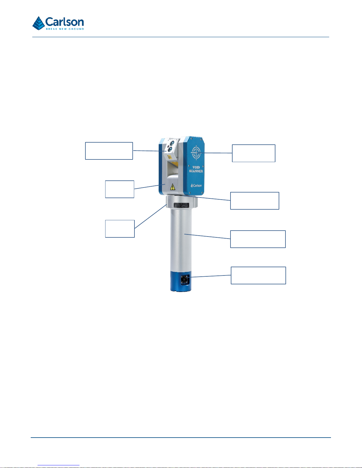
The Void Scanner instr ument consis ts of a laser m odu le held betw een two pi vots within a yoke. T he yoke its elf is
held on the end of the horizontal housing.
The laser module houses the optical and electronic components that allow distance measurements to be recorded
to reflectorless targets up to 150 m from the instrument. The laser rotates vertically within the yoke.
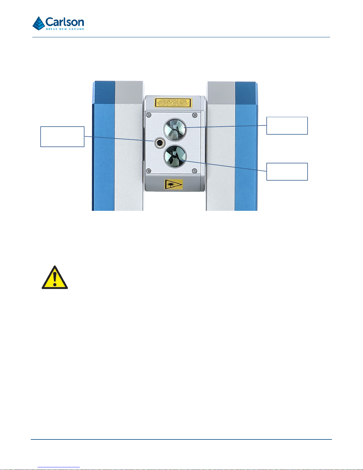
Two large lenses are visible in the laser module which represent the transmitting and receiving optics. The infrared
measuring laser is f ired thr ough th e trans m itting opt ics . Its ref lected light is then rec eived bac k into t he instr um ent
through the receivi ng opt ics. A s m aller win dow pr otec ts the visib le red dot las er pointer whic h ca n be s witch ed on
to assist aiming of the Void Scanner distance measurement laser. The pathway of the visible and infrared lasers is
co-linear, but not co-axial.
The yoke which holds the laser module contains the vertical motor which drives the movement of the laser module
between the pillars of the yok e. It also houses the vertical enc oder which m easures the a ngle through whic h the
laser is rotated.
The horizontal housing c ontains the horizontal motor which drives the rotational movement of the yoke. It also
houses the horizontal encoder which measures the angle through which the yoke is rotated.
Figure 2 Component parts of the Void Scanner
Vertical pivot
Horizontal pivot
Horizontal housing
Main cable
connector
Collar
Yoke
Laser module
Page 8
Page | 8
The combination of the two axes of rotation gives the Void Scanner a view encompassing 360° horizontal and 270°
vertical rotations r espec ti ve l y. T he yoke itself prevents the laser f r om viewing a 90° sector of t he vertical rotationa l
sweep.
Both motors are protected with clutches. This means that, if the unit is rotated by hand or
prevented from moving by an obstruction, the motors will not be damaged. It is advisable,
however, to minimise any manual movement of the unit and to keep the instrument away from
potential obstructions so the motor s may turn free ly. Neverthe less, the possibility of finger or
clothing entrapment exists. Users should not obstruct the operation of the motors or allow
clothing to come into contact with the device.
The horizontal housing incorporates four threads which provide flexibility in the method of deployment used and the
mounting position of the pri sm. Two 5/8 in threa ds – one on the base of the unit and on e on the undersid e of the
collar – allow the boom adaptor bracket to be attached to the unit.
One other 5/8 in thread, together with an M6 × 1 thread, are located along the topside of the horizontal housing and
allow two alternative positions to mount a prism during horizontal boom deployment. See section 4.8.
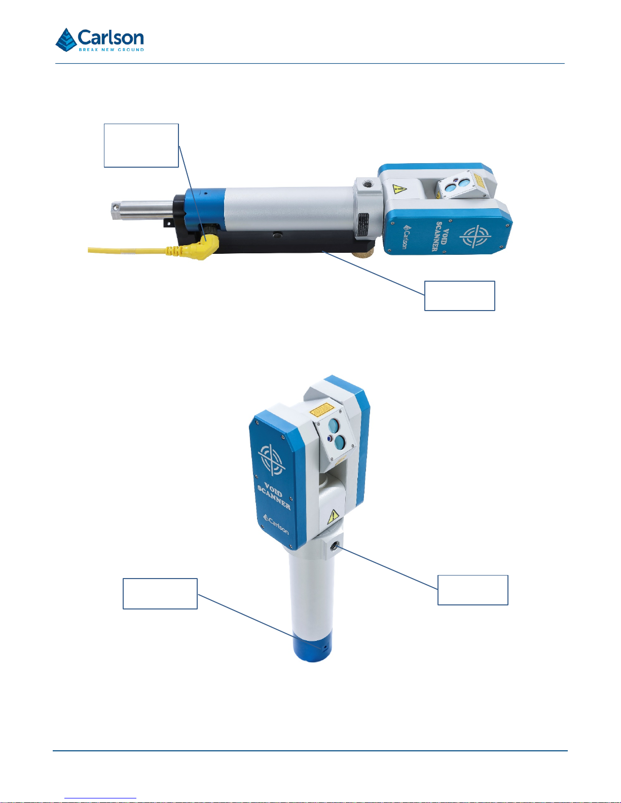
Power and data communications with the Void Scanner are via a 13.6 m Void Scanner power/data cable. The cable
connects to a 6-pin connect or on the sid e of the probe ’s hori zontal h ousing. A 4-pin connector on the other end of
the cable connects directly to either an interface box or a Wi-Fi box.
Transmitting
optics
Red dot laser
pointer
Receiving
optics
Figure 3 The Void Scanner laser module
Page 9
Page | 9
Main cable
connected to
probe
Boom
adaptor
Figure 4 Connector port location with boom adaptor
M6 x 1 thread
for prism
5/8 in thread
for prism
Figure 5 Threaded hole locations for choice of prism mounting location
Page 10
Page | 10
4.2 Interface box
The Void Scanner unit is supplied with an interface box. This box acts as a power/data splitter.
5/8 in thread
for adaptor
5/8 in thread for boom
adaptor spigot or
boom fitting
Main cable
connector to probe
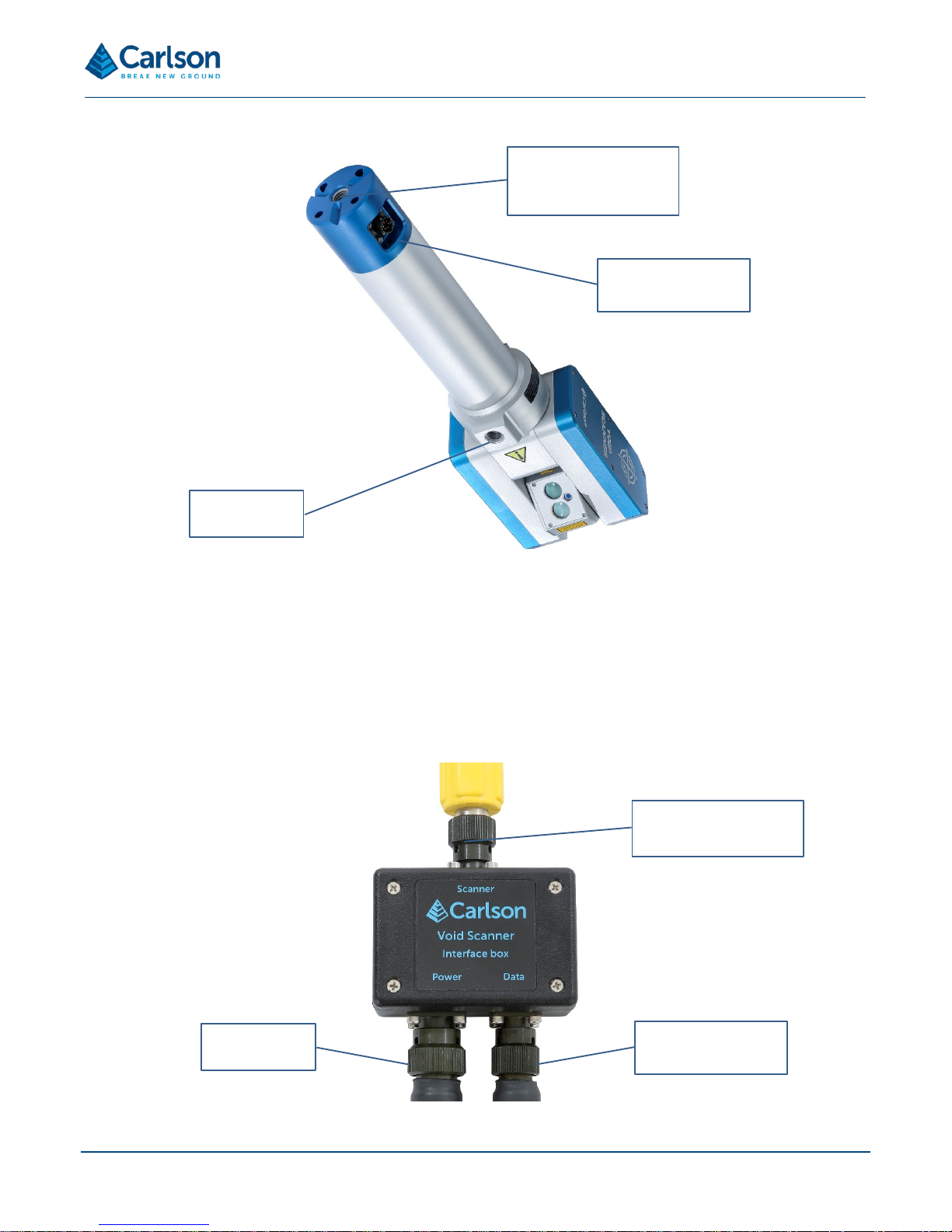
Figure 6 Threaded hole locations on the underside of the Void Scanner used for the supplied boom adaptor or other
mounting devices and booms
Power input
Connection with Void
Scanner
Serial data cable to
PC
Figure 7 Void Scanner interface box
Page 11
Page | 11
The interface box has three bayonet lock connectors:
• A 4-pin conn ector labelled Scanner which connects to the Void Scan ner data/power cable. This cab le
delivers power to the V oid Scanner and also enables two-wa y data communications between the Void
Scanner and the controlling PC.
• A 6-pin connec tor labe lled Power which accep ts po wer, either fr om the dc po wer c able with c rocod ile clip
battery connectors, or from an ac source with the power supply unit (PSU). See section 4.5.
• A 3-pin connector labelled Data which connects to the supplied serial data cable, which in turn connects to
the operating PC serial port to establish serial-based communications. See section 4.3.
The interface box is not required if the optional Wi-Fi box is used. See section 4.10.
4.3 Data cable
The Void Scanner is operated and controlled via a PC or handheld device operating Cavity Profiler – VS software.
A cable is supplied to connect the PC to the interface box or to the battery pack.
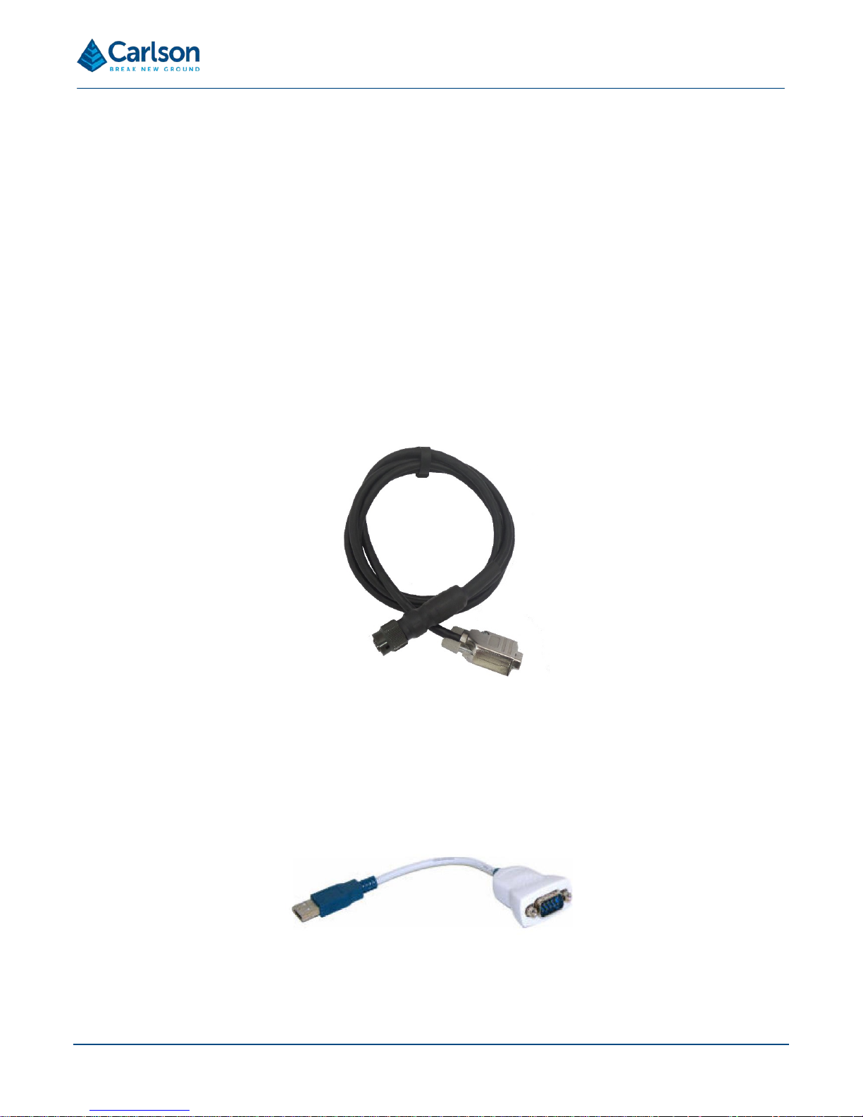
A 9-pin D-type connector interfaces with the serial communications port on the PC. A 3-pin bayonet connector then
fits to either the interface box Data port or the battery pack Data port.
A USB-serial adaptor is also supplied in case no serial por t is available on the PC. If this adap tor is used, the
accompanying driver s hould be loaded before it is us ed: see the Cavity Profiler – VS software and operations
manual for details.
If using the optional Wi-Fi box, data communications occur wirelessly, so the data cable is not required.
Figure 8 PC to interface box RS232 data cable
Figure 9 USB-serial adaptor
Page 12
Page | 12
4.4 Battery pack
The Void Scanner requires a 12 Vdc power source to operate. A dedicated 12 Vdc battery pack is supplied with the
system. The sealed lead ac id batt er y pack is rated to 7 Ah, and will al low co ntinuo us opera tion f or up to six hour s
before recharging, depending upon the type of operations conducted.
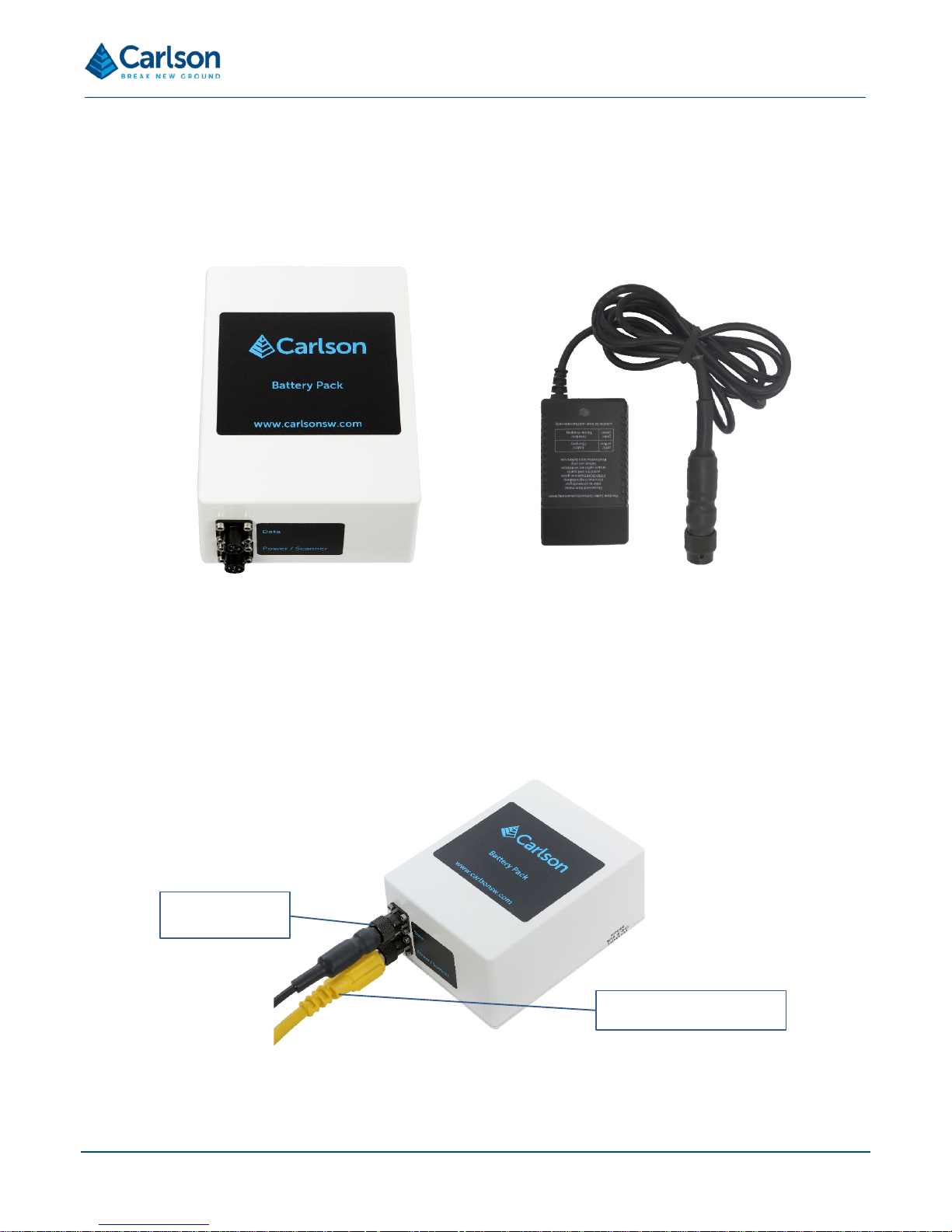
The battery pack is s upplied with two bayonet c onnectors: one with three p ins and one with four pi ns. The 4-pin
connector is labelled Power/Scanner. This wil l accept the main Void Scanner c able which runs from the Void
Scanner probe. It is also th e port to which the m ains batter y charger is attac hed when r ech arging the batt ery. The
3-pin connector is labelled Data. This will accept the supplied serial data cable which runs from the PC.
When the battery pack is used to operate the Void Scanner, the interface box is not required.
Serial cable to
controlling PC
Cable to Void Scanner
Figure 11 Power and data connection when using the battery pack instead of the interface box
Figure 10 Battery pack and battery pack charger
Page 13
Page | 13
A separate battery charger is supplied, which plugs directly into the mains and connects to the battery pack through
the 4-pin Power/Scanner connection. A fully discharged battery requires around 8 to 12 hours to fully recharge from
the mains supply. The batt ery charger is supplied with a select ion of plug types to fit mains soc kets around the
world. An LED on th e charger will s how an amber l ight while char ging and a gr een light when the battery is f ully
charged.
All batteries contain highly reactive, poisonous and corrosive chemicals, which are
hazardous if released due to physical damage. Should the battery or battery charger approach
end-of-life, become non-functional or damaged, stop using it and procure a replacement unit
from a Carlson-approved source.
4.5 Alternative external power connections
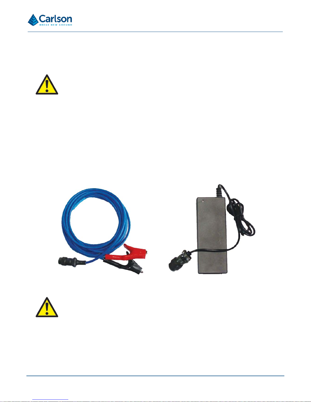
As well as the supplied battery pack , the Void Scanner may be powered from any 12 Vdc battery using the blue
cable supplied. This c able inc or porates t w o cr oc odile clips with which to conn ec t to the positive (red) and negati ve
(black) terminals of the battery.
A mains power suppl y un it (PSU) is a lso su pplie d whic h is r ated for use at 110 Va c – 240 Vac. A s tandard ‘kettle’
cable connects the PSU to the mains socket.
Both the dc and mains cab les are supplied wit h 6-pin connectors that connect to t he Power port on the interface
box.
Any voltage source connected to the Void Scanner and/or any accessory mu st be from a
regulated supply, and must be within the specified voltage range. This includes car batteries
as an acceptable stand-alone power source but does not include a car battery connecte d to a
powered vehicle, or a dc power generator.
4.6 Main Void Scanner cable
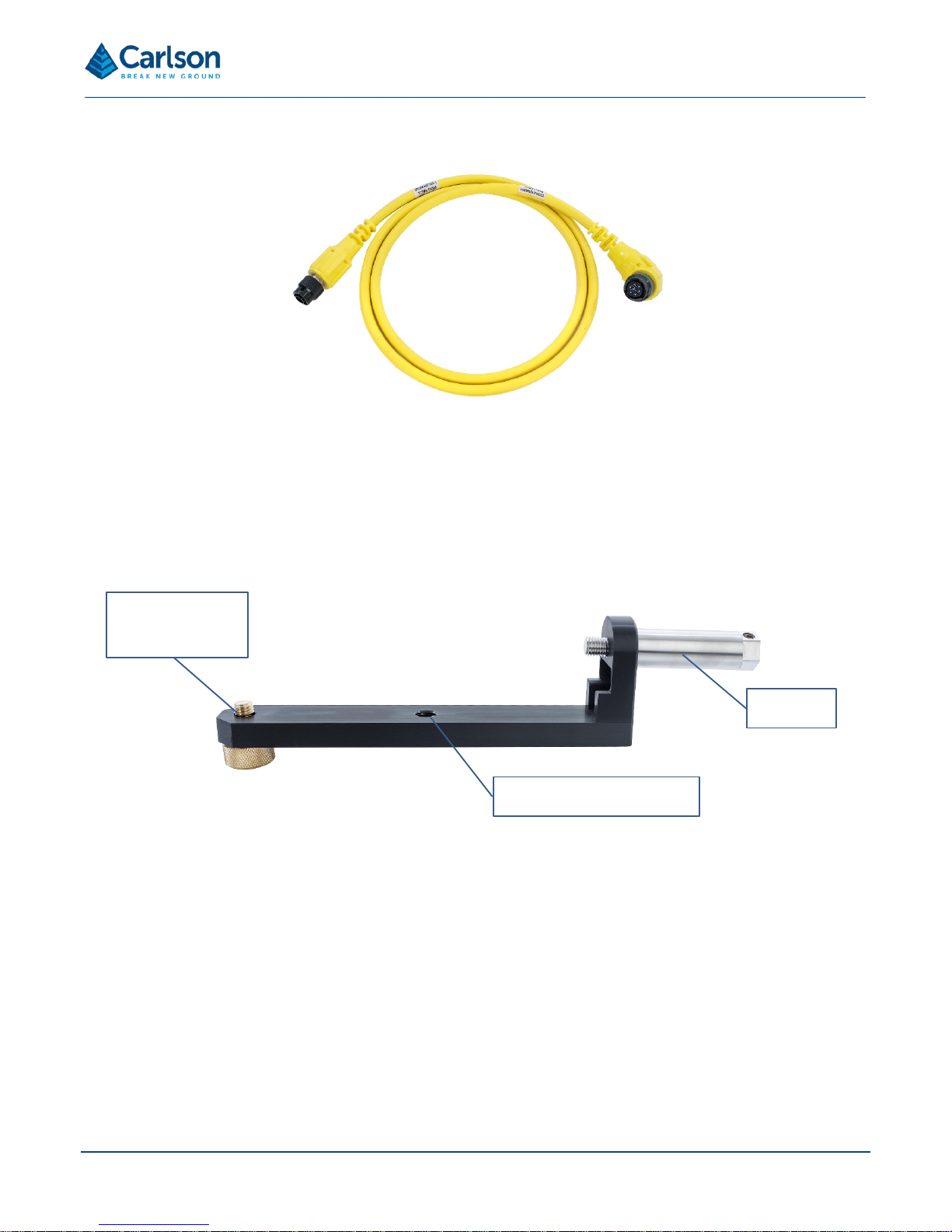
The Void Scanner is supplied with a 13.6 m toughened power/data cable. The cable incorporates a right-angled 6pin bayonet connector which attac hes to the Void Sc an ner prob e.
At the other end of the c a bl e is a 4-pi n b a yone t c onn e c tor which at taches to the interf ace box , t he battery pack, or
Figure 12 Blue dc power cable and black mains cable
Page 14
Page | 14
the Wi-Fi box, depending on how the unit is being used.
4.7 Boom adaptor and spigot
A boom adaptor is su pplied to allow the Void Sc anner probe to be deplo yed on v arious pl atforms , e.g. a boo m or
standard survey tripod. The boom adaptor is in two parts: the main bracket and a separate cylindrical spigot.
The main bracket incor porates a brass screw which connects t o the 5/8 in thread on the underside of the Void
Scanner probe. The accompanying spigot screws into the back of the boom adaptor and then into the 5/8 in thread
on the base of the Void Scanner horizontal housing.
To attach the boom ada ptor to the Voi d Scan ner prob e, locat e t he prob e on th e brac k et and s crew th e sp igot into
the 5/8 in thread located on the base of the probe. Then screw the single brass screw on the bracket into the 5/8 in
thread on the underside of the probe.
The boom adaptor itself ha s a s ingle sta ndard 5/8 in female thread to e nab le th e p r obe to b e mounted horizontally
on a survey tripod or boom.
The spigot can be used to mount the Void Scanner on a number of third-party bo om s and c ustomised deployment
devices.
Figure 13 Main cable
Brass screw for
mounting on Void
Scanner
Spigot
5/8 in thread for mounting
Figure 14 Boom adaptor and spigot
Page 15
Page | 15
4.8 Prisms
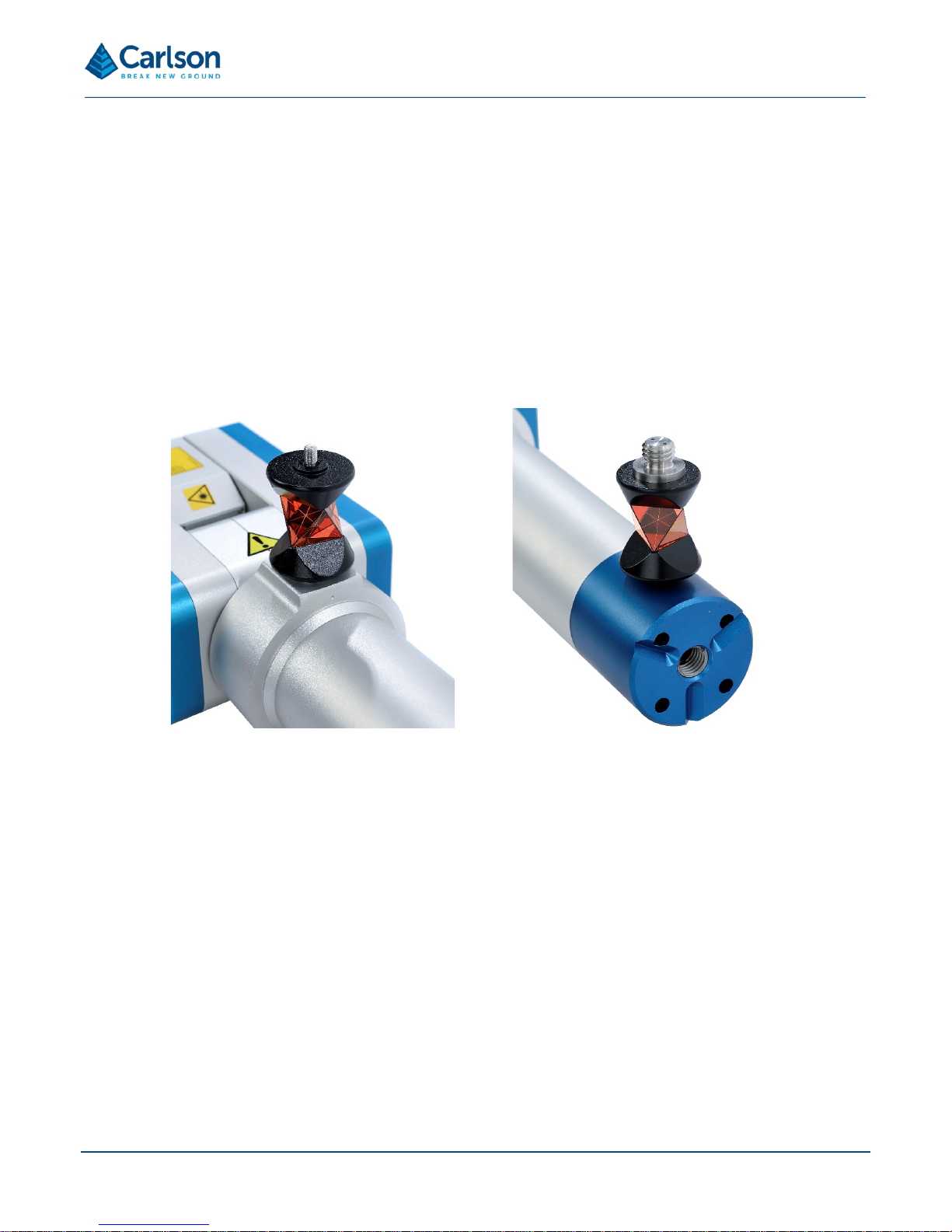
The Void Scanner is supplied with a 360° mini prism. This prism can be used to position and orientate the scanner
when the instrument is deplo yed on a boom or tripod. The prism has a 5/8 in thread at one end and an M6 × 1
thread on the other end. T hese m atc h with a 5/8 i n thr ead on th e col lar of the pro be and an M6 thr ead on the end
of the horizontal housing.
A surveyor can targ et the p rism on th e Void Scanner t o establ ish the pos ition of the unit. A secon d prism may be
attached to the far end of the deployment boom. Shooting to both prisms will then give the azimuth of the
deployment. Functionality in Cavity Profiler – VS software can assist with these calculations.
The position where the prism is mounted on the Void Scanner is c onfigured in Cavity Profiler – VS software to
ensure the coordinates of the instrument are correctly calculated. The origin of all angle and range information from
the unit is a position in the centre of the vertical axis of rotation inside the laser module.
4.9 Transit case
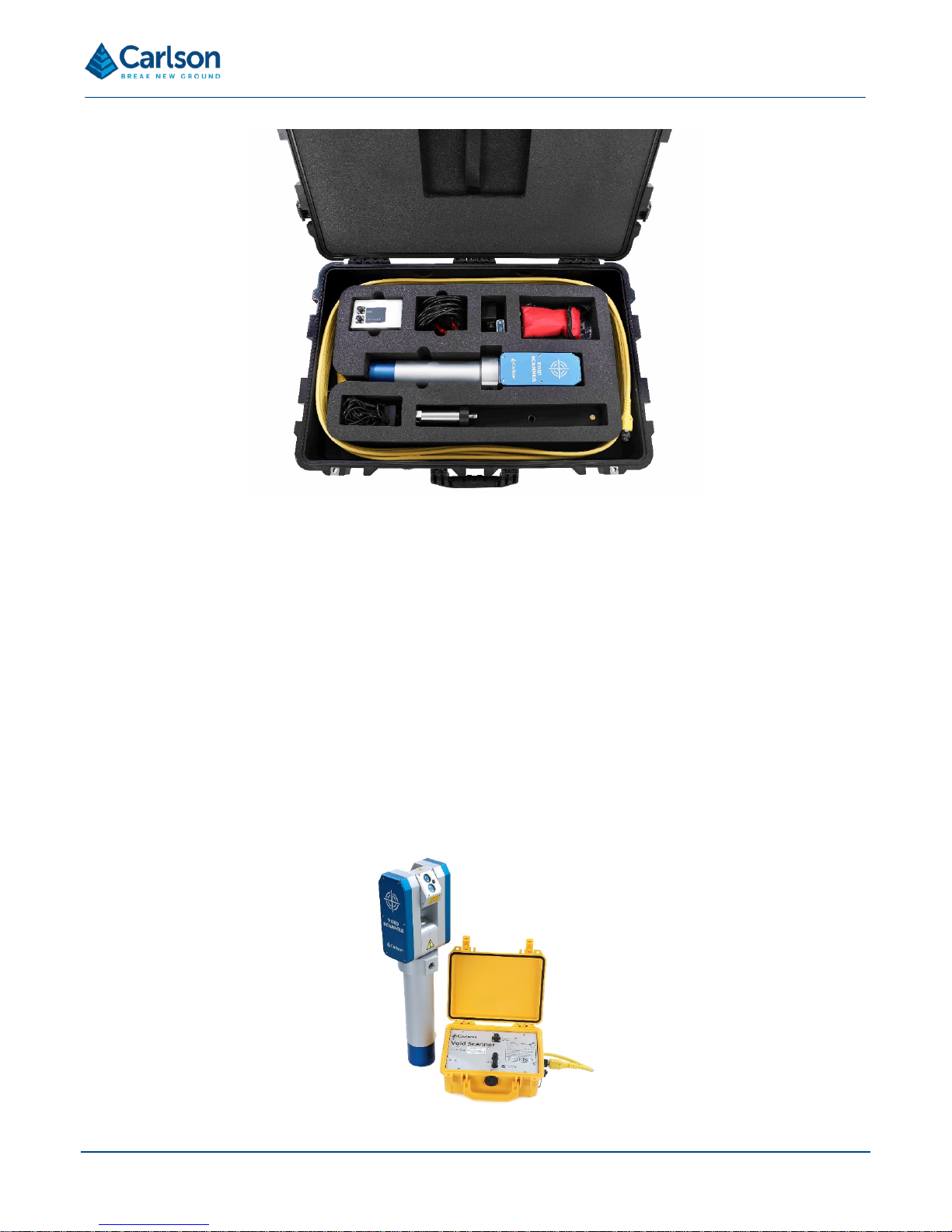
The Void Scanner s ystem is supplied i n a rugged tran sit case designed to transport the instrum ent, surface unit,
boom adaptor, battery and cables. The case helps to protect the instrument from minor shocks and from the
environment. It is recommended that the transit case be used at all times when transporting and storing the
equipment.
Take care to dry the Void Scanner probe and accessories before packing them into the transit case.
Figure 15 The 360° prism mounted on different locations on the Void Scanner
Page 16
Page | 16
4.10 Void Scanner Wi-Fi box
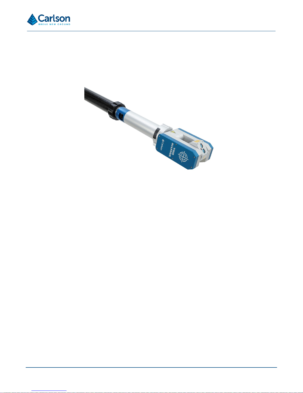
The Void Scanner Wi-Fi box is an optional accessory that houses a rechargeable battery and wireless module. The
Void Scanner Wi-Fi box negates the need for a separate battery pack, power cable, data cable and interface box.
The Void Scanner Wi-Fi box can be us e d to al lo w per sonne l to r etr eat f urt h er f r om the s c ann er. The unit may also
be attached to the probe boom that is extended into the unsaf e area, or placed on an u nmanned vehicle that is
remotely driven into the unsafe ar ea. You can be s ituated in a safe ar ea nearby, recei ving scan data w irelessly,
directly to your laptop.
The Void Scanner Wi-Fi box connec ts to the Void Sc a nner prob e v ia th e s tan dar d 13.6 m power/data cable, or via
the 1.5 m power/data cable supplied with the box. Connection to the PC is then via wireless data communications.
A separate Void Scanner Wi-Fi box manual is available which contains set-up and operational instructions together
with full hardware specifications.
Figure 16 System tran sit ca se
Figure 17 Void Scanner with Wi-Fi box
Page 17
Page | 17
4.11 Booms and deployment devices
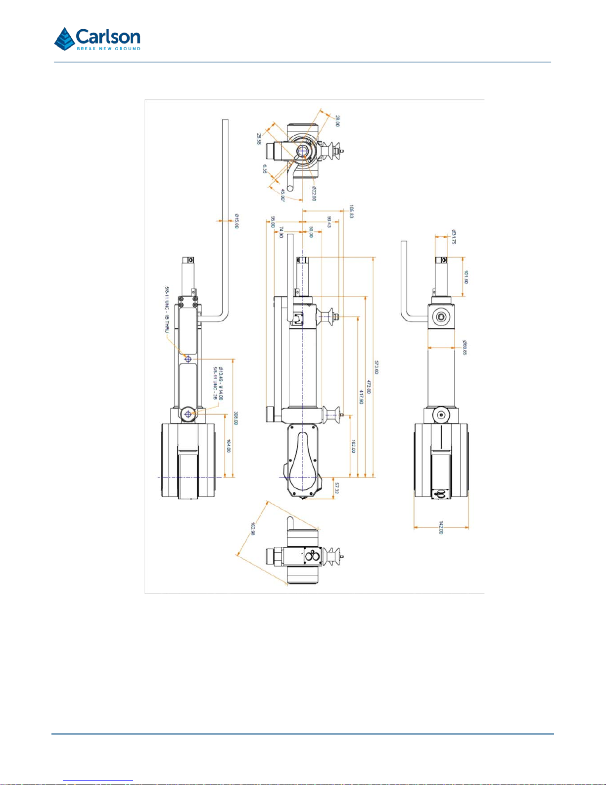
The Void Scanner is designed to be deployed on a boom for surveys of stopes and inaccessible areas. Carlson can
offer a standard boom as an optional acces sory with t he unit. Altern ativel y, man y users design their o wn boom or
other deployment device to suit their specific operational and site requirements. In some cases the probe fits directly
to the deployment device. In other cases, where there are different mec hanical configuratio ns, the boom adaptor
may be required.
Due to the wide range of possible ways of deploying the Void Scanner, this manual does not describe any method
of attachment in detail. For further advice and information, contact your local Carlson-approved service and support
centre.
If you wish to design your own c us tomized deployment devic e, th e r elev ant dr a wi n gs and d imensions of the probe
and the boom adaptor are reproduced below.
Figure 18 Void Scanner mounted on a boom
Page 18
Page | 18
Figure 19 Void Scanner probe and boom adaptor dimensions
Page 19

Page | 19
5 Maintenance and care of the Void Scanner
5.1 General
Attempts to dismantle or r epair the Void Scanner and access ories can be hazardous and costl y if attempted by
untrained personnel. Un authorised attempts to c ar r y out maintenance work on th e equ ipment will void all wa rr ant y
cover. Maintenance c arried out by the oper ator therefore, should be r estricted to the cleaning a nd inspection of
external surfaces, lens windows and operating controls.
In addition, you shoul d carry out r egular func tional test ing of the s ystem . Detect and repor t dam age, malf unctions
or poor performance to Carlson or a local Carlson representative.
Arrange a yearly calibr ation for your Void Scanner syst em to ensure that it is kept in o ptimum condition and to
ensure the highest possible quality of data.
A troubleshooting guide which outlines some of the most common support questions is included in the
accompanying Void Scanner software and operations manual. For other issues, contact Carlson or a local Carlson
representative for further assistance.
5.2 In use
Avoid directing the Void Scanner laser towards the sun or other high-power infrared light sources.
Avoid mechanical shock.
Avoid manually moving t he sc an head, eith er horizo ntally or verticall y, as this ca n strain the mec hanics with in the
probe.
Ensure the boom or other mounting s ystem is s ecurely set up and on s table ground t o a void the instrument being
disturbed or knock ed over. When moving from one i nstr um ent set-up t o an other, alwa ys detac h the Voi d Sca nner
from the boom or tripod and carry the two items separately.
The supplied battery pack will benefit from being kept fully charged and receiving steady use. Recharging the battery
after a short period of use will not affect its performance or life expectancy.
Inspect and check the probe and accessories for wear, tear and damage after each use.
Always clean and dry the equipment after use. See below for details.
5.3 Cleaning the Void Scanner
Always ensure that the Void Scanner and all accessories are thoroughly cleaned and dried before packing them in
the transit case after a deployment.
Use clean water to remove mud, grit and other materials from the main body of the probe after use. Do not immerse
the Void Scanner in water. The Void Scanner is rated IP66: it is dust-tight and protected against high pressure water
spray from all directions, but not against submersion.
For further cleaning of the Voi d Scanner m etalwor k and sid e pane ls, Carls on rec omm ends that you us e a produc t
such as Amberc lens anti-static foam clean er. If this is not a vailable then use a gener ic, mild dishwashing liquid
diluted in warm water ( 0.001%, i.e. 1 ml for every 1l of water). Do not use paint solvents or any other personal,
laundry, or household clea ning detergents as they may contain chem icals that could corrode seals in the Void
Scanner. Apply the diluted detergent with a non-abrasi ve, lint -free cloth.
Page 20

Page | 20
Rinse the unit with plain water after using a detergent.
Dry the unit thoroughly after cleaning. Where possible, leave the unit unpacked until it is dry. In case the system is
packed before it has dried, the equipment should be unpacked at the earliest opportunity. Clean and dry the system,
and the inside of the transit case, before repacking the Void Scanner for storage.
To clean the lens windo ws and the red d ot laser po inter windo w on the laser m odule, use HPLC -grade (> 99.8%)
acetone in combination with lint-free cotton wool buds or wipes .
NOTE: repeated exposure to acetone may cause skin dryness or cracking. It is recommended that personal
protective equipm ent (PPE) such as eye-shields and/or face-shields as well as protective gloves is used when
dispensing and using HPLC-grade acetone.
5.4 Storage and transportation
Dry the system thoroughly before storing.
If the instrument remains unused for several weeks, it is advisable to remove power sources from the instrument.
Store within the environmental temperature limits of -25° C to +70° C.
Before transporting the Void Scanner system, pack the equipment correctly in the supplied transit case.
Secure the transit case to prevent the possibility of shock or vibration.
Do not allow the transit case to slide around inside transport vehicles or containers.
Page 21

Page | 21
6 Cavity Profiler – VS software
The control and processing software for the Void Scanner is known as Cavity Profiler – VS. Cavity Prof iler – VS
enables the Void Scann er t o be co ntrolle d rem otely du ring f ield oper atio ns. It a llows r eal-time viewing of coll ected
data, analysis and editing of all datasets, the integrati on of further scans and the exporti ng of data to third-party
packages.
Full details of the software, together with basic operation guidelines, are outlined in the accompanying Cavity Profiler
– VS software and operations manual.
Page 22

Page | 22
7 Void Scanner Specifications
Laser module
Laser classification BS EN 60825-1:2007
(21 CFR 1040.10 and 1040.11 except for
deviations pursuant to Laser No. 50, dated 24
June 2007)
Class 2M*
Infrared laser module
Type InGaAs laser diode
Wavelength (typ) 905 nm
Maximum energy per pulse 1.06 μJ
Beam divergence 2.76 × 1.5 mrads
Resolution 1 cm
Maximum range to a passive target** Up to 150 m
Minimum range 0.5 m
Lens aperture size 18 mm - location at front of module
Visible laser module
Type InGaAsP laser diode
Wavelength (typ) 650 nm
Maximum power < 0.6 mW (continuous wave)
Lens aperture size and location 3 mm (location at front of module)
Angle measurement
Encoder type Opto-electronic encoder
Encoder accuracy 0.02°
Encoder resolution 0.1°
Mechanical range
Vertical −135° to -135°
Horizontal 0° to 360°
Mechanical motion Servo-driven gear systems with manual clutches
Pitch and roll sensors
Type Triaxial, digital accelerometer
Pitch and roll accuracy ±0.2°
Pitch and roll range 360°
Construction
Probe Machined aluminium and stainless steel
Environmental
IP degree of protection (probe)*** IP68 (pressure rated to 30 bar, equivalent to 300 m water depth)
Operating temperature −10 °C to +45 °C
Storage temperature −20 °C to +70 °C
Page 23

Page | 23
Physical
Weight
Dimensions
Probe (including batteries) 3.2 kg 710 mm × 40 mm (L × Dia)
Rods (individual) 400 g 1000 mm × 30 mm (L × Dia)
PDA (including batteries) 280 g 155 mm × 83 mm × 24 mm (L × W
× D)
Power
External power input 10 Vdc to 15 Vdc and 110 Vac to 240 Vac
Power consumption during scan 9.6 W (typically)
* Viewing laser output with optical instruments designed for use at a distance (e.g. binoculars) may pose an eye hazard.
** Maximum measuring ranges are recorded against Kodak white card (90% reflectivity).
*** Environmental compatibility requirements of EN 60529:1992+A1:2002.
Page 24

Page | 24
8 Product information
© 2018 Carlson. All rights reserved.
This document may not be copied or reproduced
in whole or in part, or transferred to any other media or language,
by any means, without the prior written perm is sion of Carlson.
The publication of material within this document does not imply freedom from the patent rights of Carlson.
Trademarks
CARLSON and the symbol used in the CARLSON logo are registered trademarks of Carlson in the United Kingdom
and other countries. ‘Breaking new ground’ and names and designations of other Carlson products and technologies
are trademarks of Carlson or its subsidiaries.
All other brand nam es and product names used in this docum ent are trade names, trademarks, or registered
trademarks of their respective owners.
Changes to Carlson products
Carlson reserves the right to improve, change or m odify its products and documentation without incurring any
obligation to make changes to equipment previously sold or distributed.
Carlson has made consider able eff orts to ensure the c ontent of this document is correct at the date of publicatio n
but makes no warranties or representations regarding the contact. Carlson excludes liability, howsoever arising, for
any inaccuracies in the document.
Warranty
Unless otherwise specified, Carlson warrants all supplied equipment for a period of 12 months from the date of
delivery. This warranty is given subject to the following conditions:
• Carlson shall b e under no liability in respect of any defec ts in the equipment arising from any drawing,
design or specification supplied or modification requested by the customer.
• Carlson shal l be under no liabilit y in respect of def ects arising f rom willful dam age, neglige nce, abnorm al
working conditions, f ailure to f ollow Car lson’s instr uctions (whether or al or in writin g), mis use or alterat ion
or repair of the equipment without Carlson’s approval.
• Software is not covered by this warranty.
• Claims in respect of def ective equipment must be made in writing to Carlso n and the equi pment mus t be
retained by the customer pending written instructions from Carlson.
Following authorised return of the equipment, which must be made by the customer on freight prepaid basis,
Carlson will examine the equipment and, if the claim is justified in Carlson’s opinion, will repair the defective
equipment or will make replacement without charge. Carlson will have no further liability to the customer.
Safety
The Void Scanner is a robust, ruggedized, field instrument whose applications include the 3D mapping of
underground stopes, voids and tun nels. Unit range is 150 m to non-reflectiv e surfac es. It is es sentia l that th e unit
and all accessories are operated in acc or d anc e with th e ins truc tio ns in th is us er manual and it is the r espo ns i bility
of the user to ensure that, in the event of a failure on any part of the Carlson system, the equipment remains safe.
In the case of equipm ent with powers or speeds cap able of causing injur y, it is essential that appropr iate safety
measures are incorporated into the equipment operation. Further guidance can be found in the European Standard
EN292 Safety of machinery – General principles of des ign – Risk assessment and risk reduction.
Page 25

Page | 25
The safety of any operations involving the Quarryman Pro system is the responsibility of the operator.
Information to the equipment supplier/ installer
It is the equipment s upplier’s responsibilit y to ensure that the user is made aware of any hazards involved in any
operations involving the Rodded Boretrak system, including those mentioned in Carlson product literatur e.
Safety information
This symbol is used in this manual wherever important safety information is present.
Before proceeding with any electrical connection or operation of the laser system, refer to the general
safety information throughout this manual.
EC declaration of conformity
Carlson declares that the Void Scanner complies with the applicable standards and regulations.
Contact Carlson or visit www.carlsonsw.com
for the full EC declaration of conformity.
FCC (USA only)
Information to the user (47CFR section 15.19)
This device complies with part 15 of the FCC Rules. Operation is subject to the following two conditions:
1. This device may not cause harmful interference, and
2. This device must accept any interference received, including interference that may cause undesired
operation.
Information to the user (47CFR section 15.21)
The user is cautioned that any changes or modifications not expressly approved by Carlson or authorised
representative could void the user’s authority to operate the equipment.
Information to the user (47CFR section 15.105)
This equipment has been tested and found to comply with the limits for a Class A digital device, pursuant to part 15
of the FCC Rules. T hese lim its are designed to pr ovide reasonab le protection ag ainst harmf ul interference when
the equipment is operated in a c ommercial environment. T his equipment generates, uses and can r adiate radio
frequency energy and, if not installed a nd used in accordance with the instr uction manual, may cause harmf ul
interference to radi o communications. Operation of this equ ipment in a resid ential area is lik ely to cause harm ful
interference in which case the user will be required to correct the interference at his own expense.
WEEE directive
Page 26

Page | 26
The use of this symbol on Carlson products and/or accompanying documentation indicates that the product should
not be mixed with general household wast e u pon dis p osal. I t is t he r es pons i bi lity of the end user to disp os e of this
product at a designated col lection point for waste el ectrical and electronic equipm ent (WEEE) to enable reuse or
recycling. Correct disposal of this product will help to save valuable resources and prevent potential negative effects
on the environment. For more information, please contact your local waste disposal service or Carlson
representative.
Battery disposal
The use of this symbol on the batteries, packaging or accompanying documents indicates that used batteries should
not be mixed with general househol d waste. P leas e dispos e of the us ed batteries at a des ignate d collec tion point.
This will prevent potential negative effects on the environment and human health which could otherwise arise from
inappropriate waste handling. Please contact your local authority or waste disposal service concerning the separate
collection and disposal of batteries. All lithium and rechargeable batteries must be fully discharged or protected from
short circuiting prior to disposal.
 Loading...