

Page 1
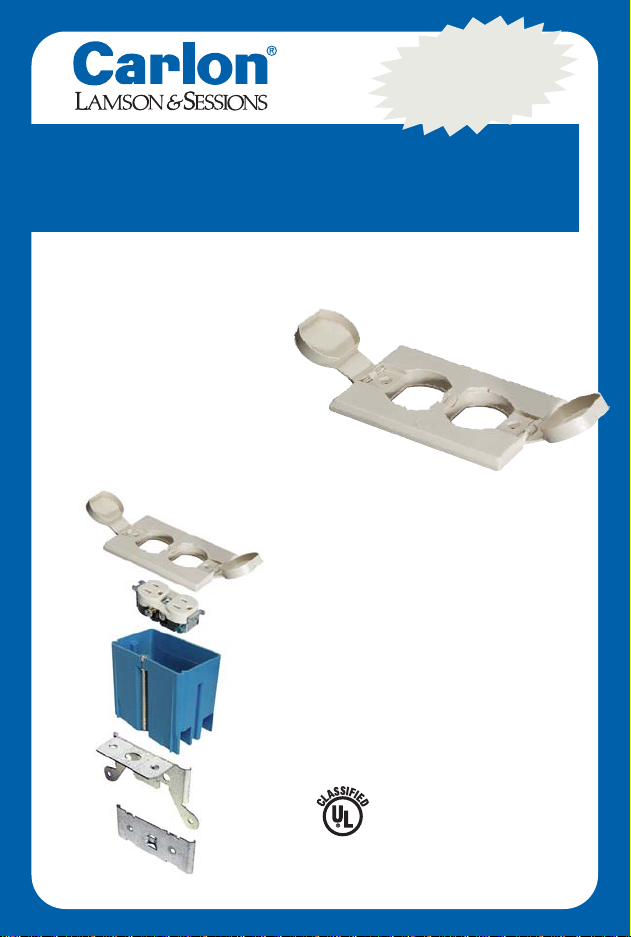
Adjustable Floor Box
Kit with White Cover
THE FAST, EASY WAY TO PUT A PLUG
ANYWHERE YOU NEED IT!
• Eliminates extension
cords
•Great for home offices &
entertainment rooms
• Easy to use – kit
includes everything you
need!
ADJUSTS TO MOST
FINISHED FLOOR HEIGHTS!
Kit includes:
• Nonmetallic White
Cover
• Adjustable 20 cu. in.
Nonmetallic Floor Box
• Duplex Receptacle
• Molded Cable Clamps
• Mounting Bracket
• All mounting hardware
2-HR-F
FLOOR BOX
696Y
Assembled in USA
Patent #5,289,934
B121BFBRW
NEW!
Page 2
INSTALLATION INSTRUCTIONS
This floor box is designed to be mounted on a
joist or subfloor. It can be installed on the top of
the joist or from the bottom if the thickness of
the joist is sufficient to allow installation of the
box. If the unit is to be installed from the bottom
of the joist, check prior to installation to ensure
there is sufficient adjustment remaining as this
type of installation is non-standard.
The unit can also be installed using the old work
(small) bracket that is included. This bracket
facilitates the installation of the box in areas
where the larger new work bracket cannot be
used. The old work bracket edge is hidden by the
cover when installed. However, before cutting into
the wood, you must ensure that the mounting
screws will properly support the bracket/box
installation.
For planning purposes please ensure that the
maximum installed height to the bottom of the
cover does not exceed 1-3/4" above the top of the
mounting bracket.
The kit is listed as a floor box by Underwriters
Laboratories. The kit also has a two (2) hour fire
classification. Only covers manufactured for this
box can be used with this assembly.
Floor box kit should be installed by a certified
electrician.
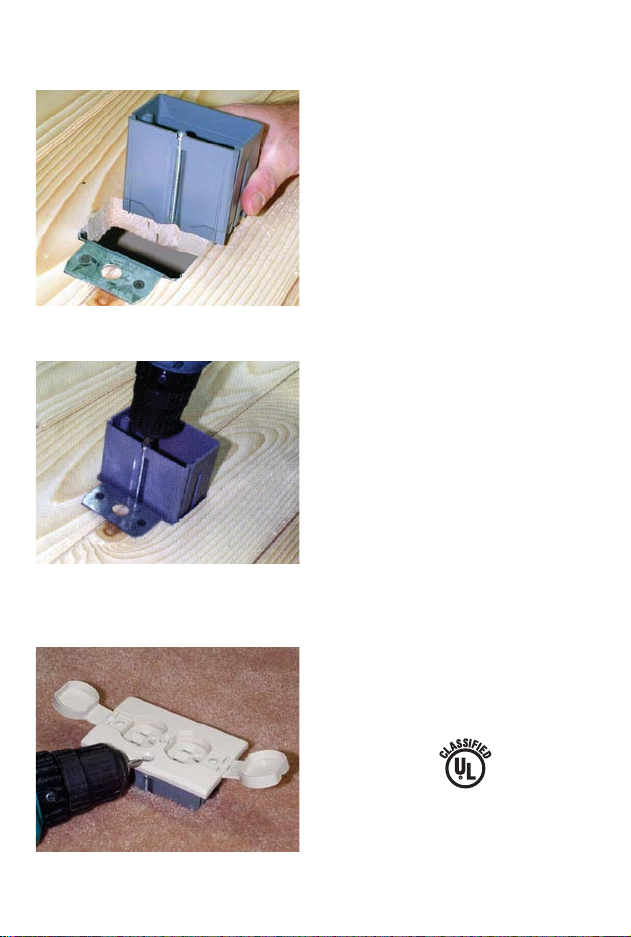
Install clip over subfloor.
Screw in to adjust to height
of flooring or carpet.
Beautiful flush fit every time!
2-HR-F
FLOOR BOX
696Y
Assembled in USA
Patent #5,289,934
Page 3
Installation – New Work Bracket
1. The new work metal bracket may be installed on the
floor joist below a 3/4 inch subfloor. When a thicker
subfloor is used we recommend cutting a hole in the
subfloor using the box as a template and adjacent to
the joist so the mounting screws will engage the joist
as well as the subfloor. Use the four (4) #6 1-3/4"
self-tapping screws suppled with the kit to mount the
bracket.
2. If the new work bracket is installed from the underside of the joist, ensure the alignment with the box
and opening before installing the bracket. Use the
four (4) #6 1-1/4" self-tapping screws supplied with
the kit to mount the bracket.
3. The romex wire can then be pulled through the
desired clamp and the box aligned in the bracket
slide. Ensure the adjusting screw is aligned on the
bracket and rotate the screw clockwise using an electric or pneumatic POWER screw gun. (The adjusting
screw can be turned manually with a screwdriver, but
this is a self-tapping screw that is cutting threads
into hardened steel and it will be very, very difficult.)
4. Adjust the box flush to
1
/2" above floor, leaving
sufficient room to complete the installation.
5. Wire the receptacle in accordance with the National
Electrical Code.
6. Cut the top of the tube containing the Dow Corning
#4 sealant and apply an 1/8 inch bead of the sealant
around the outside rib of the cover that mates with
the box. Align the receptacle on the recessed bosses
and place the cover on the box with outlet caps open.
Push cover into the box until rib on bottom of cover
engages with box.
7. Insert the two (2) 6-32x1 inch flat-head machine
screws in the holes in the cover, ensuring that the
screw is aligned with and captivates the receptacle.
DO NOT OVER TORQUE. Tighten the screws to a
maximum of 6 to 8 inch pounds. Ensure bottom of
cover is still engaged with box.
8. Remove the plug on the cover that hides the adjusting screw opening and set it aside where it will not
be misplaced.
9. Using the adjusting screw, adjust the assembly so
cover flange is flush with floor covering. Do not preload the cover against the floor covering. Place the
“button” you previously set aside in a safe place over
the adjusting screw opening.
10. In order to ensure a watertight seal, apply a thin layer
of the Dow Corning #4 sealant around the cap and
cover mating surfaces.
11. Turn the coin slot lock in the center of the cover in
either direction to lock the outlet caps.
Installation – Old Work Bracket
1. As indicated in the prior instructions,
ensure there is sufficient depth of
the floor covering to install the old
work bracket. If not, the bracket
must be installed adjacent to a joist
where the screws will engage the
joist/flooring for support.
2. Use the box as a template and cut
out an opening in the floor cover.
3. Place the bracket on the side of the
opening where it is to be mounted
with the two tabs up and resting on
the surface. (Be careful not to drop
the bracket into the opening.)
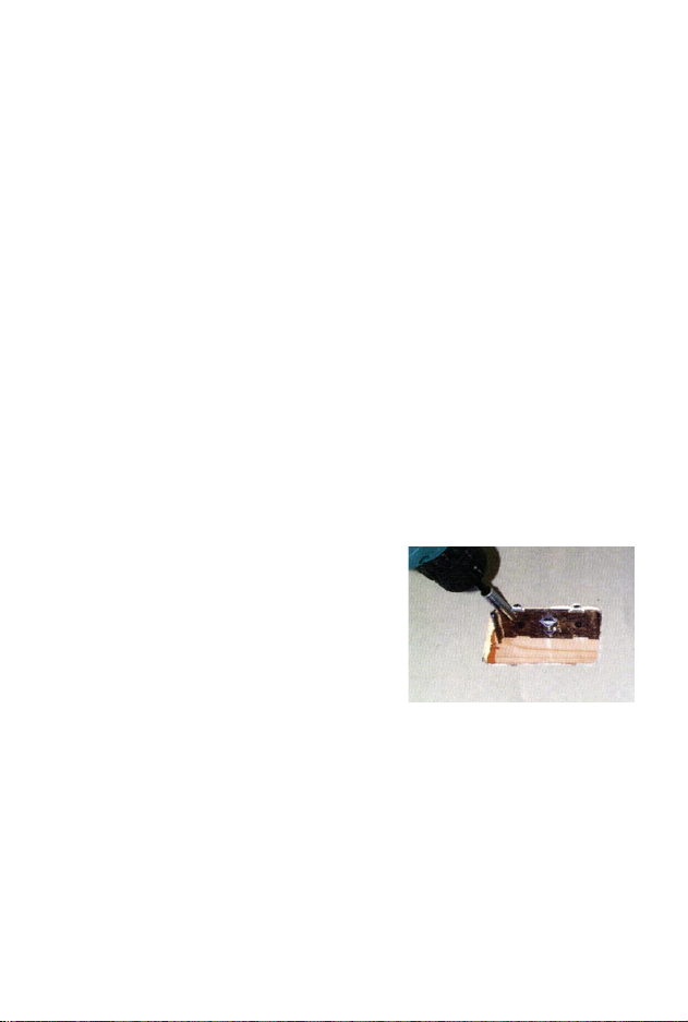
4. Install the bracket using the two (2)
square drive trim head screws
provided in the kit. Since the screws
are installed at an angle, there may
be a small part of the screw head
that protrudes. This is to be anticipated and will not interfere with the
installation of the box.
5. Use the installation instructions for
the new work bracket from this point
forward starting with step 3.
Old work bracket
installation for tight
locations or cut-in
situations
MAINTENANCE
To ensure continued service, it is
recommended that the sealing surfaces
of the caps and cover be kept free of
debris.
Page 4
25701 Science Park Drive • Cleveland, Ohio 44122 • www.carlon.com
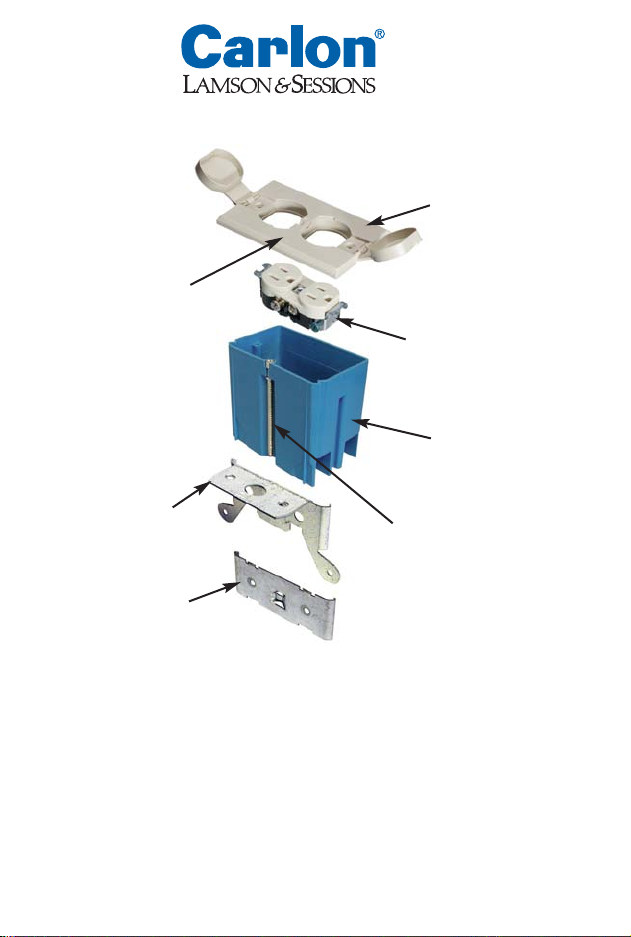
Adjustable
Floor Box
Assembly
• One (1) New Work Bracket
• One (1) Old Work Bracket
• One (1) 20 cubic in. UL Listed floor box
• One (1) UL Listed white floor cover
• One (1) short shank receptacle
Package Contents
Plug
White Cover
Receptacle
Adjusting Screw
New Work Bracket
Old Work Bracket
20 cu. in. Floor Box
• Two (2) 6-32x1 flat head machine screws
• Four (4) #6 1-1/4 self-tapping flat head screws
• Two (2) #6 square drive trim head screws
• One (1) tube Dow Corning #4 sealant
• Installation instructions
Caution: The floor box has undergone a scrub water test as required by UL under criteria
specified in 514C for this type of application. However, it is not intended for nor approved for
wet locations or outdoor installation.
IS121W 01/03
© Lamson & Sessions 2003
 Loading...