

Page 1
25701 Science Park Drive,
Cleveland, Ohio 44122 USA
CALL TOLL-FREE OR FAX
Tel: (800) 3-CARLON (1-800-322-7566)
In Ohio: (216) 464-3400
FAX: (216) 766-6444
TDD/Hearing Impaired Access:
(216) 831-5918
www.carlon.com
In Canada, contact:
P.O. Box 60
35 Killaloe Road
Unit 4 Concord, Ontario
Canada L4K 1A0
(905) 660-7993
(888) 269-9902
Fax: (905) 660-9663
(888) 229-8622
Carlon
®
Round
Non-Metallic
Floor Box
Installation
Instructions
IS6
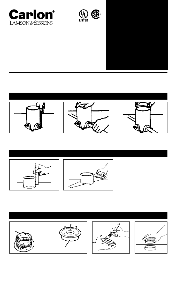
1. Set floor box on level surface. 2. Make connections into outlets
by solvent cementing conduit
into proper outlet in box.
3. Slip on throwaway plastic cap
and seal unused outlets with
solvent cemented plugs.
1. INSTALLATION IS EASY
3 Simple Steps
to Install Non-Metallic Floor Box in Cement
1. Remove plastic cap and determine
thickness of flooring to be used.
Scribe a line around floor box at
this distance from floor.
2. Using handsaw, cut off floor box
at scribed line.
2. TRIM OUT IS A SNAP
1. Install mounting ring to underside of cover.
NOTE: Box may extend any distance above flooring. Box is cut off to exact height with a handsaw.
Mounting ring assures a LEVEL top, every time.
3. INSTALL COVER Refer to installation instructions provided with cover.
Nonmetallic cover mounting
ring (Leveling Ring)
Metal cover adapter mounting ring
E42728
3. Press mounting ring
cover assembly into
floor box.
2. Carefully apply Carlon
PVC Cement to
mounting ring only.
Page 2

1. Establish location of floor box on sub floor.
2. Cut a 5" round hole in sub floor.
3. a. If nonmetallic Sheathed Cable is used for wiring, cement Carlon
Strain Relief Connector with Grommet, Part No. H978E in
3
/4" box
opening.
3. b. If Electrical Nonmetallic Tubing (ENT) is used for wiring, solvent weld
ENT in hub using Carlon ENT Cement.
3. c. Cement the plugs provided in unused openings. Refer to Figures
No. 1, No. 2, and No. 3.
4. Cut wooden 2" x 6" support to fit between joist spacing. Refer to Figure
No. 1 or Figure No. 2.
5. Secure floor box to the 2" x 6" with four (4) #10 x 1" screws. Refer to
Figure No. 3 (NOTE: SCREWS ARE NOT PROVIDED).
6. From floor below, insert the floor box through the hole in sub floor to
desired height. Secure support by using one of the following methods
listed below.
6. a. WOODEN JOIST CONSTRUCTION:
Use three (3) 16d nails on each side of floor joist to secure box
support between WOODEN FLOOR JOISTS. Refer to Figure No. 1.
6. b. METAL JOIST CONSTRUCTION:
Use three (3) 3" self-drilling screws on each side of metal floor joist,
to secure wooden box support between METAL FLOOR JOISTS. Refer
to Figure No. 2.
7. Follow floor box cover installation instructions provided with cover.
ROUND FLOOR BOX PART NO. E971FB
3 Simple Steps
to Install Non-Metallic Floor Box in
Wood & Metal Joist Construction
E42728
Page 3

Carlon Strain
Relief
connector &
grommet
Part No.
H978E
Carlon Strain
Relief
connector &
grommet
Part No.
H978E
Cut to height. Flush with
finished floor surface
WOOD JOIST CONSTRUCTION
Figure 1
METAL JOIST CONSTRUCTION
Figure 2
Figure 3
Subfloor
Plug unused
openings in box.
Plug unused
openings in box.
2" x 8"
2" x 8"
2" x 8"
2" x 8"
2" x 6" - cut to fit joist spacing
2" x 6" - cut to fit joist spacing
16"OC
16"OC
Cut to height. Flush with
finished floor surface
Subfloor
Install box on 2"x 6", slide between floor joists,
mark outline of box on bottom of subfloor, mark center drill hole thru floor to install box.
Carlon Strain Relief
connector & grommet
Part No. H978E
Plug unused openings in floor box.
ENT
1" screws
1" screws
Romex
Solvent
weld with
ENT cement
For wood construction-
(3)-16d nails each end
For metal construction-
(3)-3" self-drilling
screws each end
Page 4

IS6 11/99
© Lamson & Sessions 1999
www.carlon.com
E42728
 Loading...