

Page 1
www.carlonsales.com
6
Multi-Gard®PVC – Assembly/Field Cuts
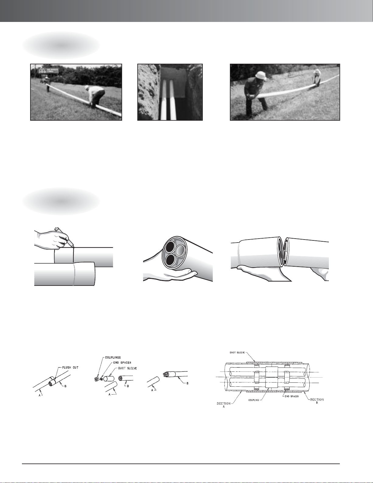
Assembly
Field Cuts
1.
Distribute Multi-gard sections along
the sides of the trench with male ends
pointing towards starting vault entrance.
2.
Remove protective cap and
install Multi-Gard terminator on
male end. Install first section
into vault opening or enclosure
making sure the print line is on
the top stating “INSTALL PRINT
LINE UP.” (See next page for
terminations.)
2. A spare spacer may be
installed to align the innerducts
if they seem loose.
2. Align innerducts on Multi-Gard section “A” with
couplings on section “B”. Solvent cement each coupling
for air tight seal and push until both ends are flush.
Apply solvent cement to both ends of Multi-Gard and
slide sleeve until it is centered on both sections.
3.
Each consecutive 20' section can now be
placed by inserting the male end into the gasketed belled end 1/2
" to the gasket depth. Make
sure the print line is upright. (If not, rotate the
outer duct until it is.) Now push the sections
together with a firm push until belled end seats
against insertion line.
3. Raise both ends and align the innerducts
on the male end into the coupling body on
the female end. Lower both ends and the
innerducts will automatically return to their
original position as the joints are forced
together.
Joining Male and Female Ends
Joining Two Male Ends
1. Lay the Multi-Gard sections side by
side and mark the male end at the
base of the bell on the female end.
Make a straight cut using
a standard carpenter saw.
1. Flush cut Multi-Gard sections “A” + “B” as shown in figure 1. Slide
outerduct sleeve over Multi-Gard section “B” as shown in figure # 2.
Insert end spacer into Multi-Gard plain end (chamfer side in) as
shown in figure #2. Press couplings onto innerducts of Multi-Gard
section “B” as shown in figure #3.
FIGURE 1
FIGURE 2
FIGURE 3
M CC4
–
Gross Automation (877) 268-3700 · www.carlonsales.com · sales@grossautomation.com
Page 2
www.carlonsales.com
7
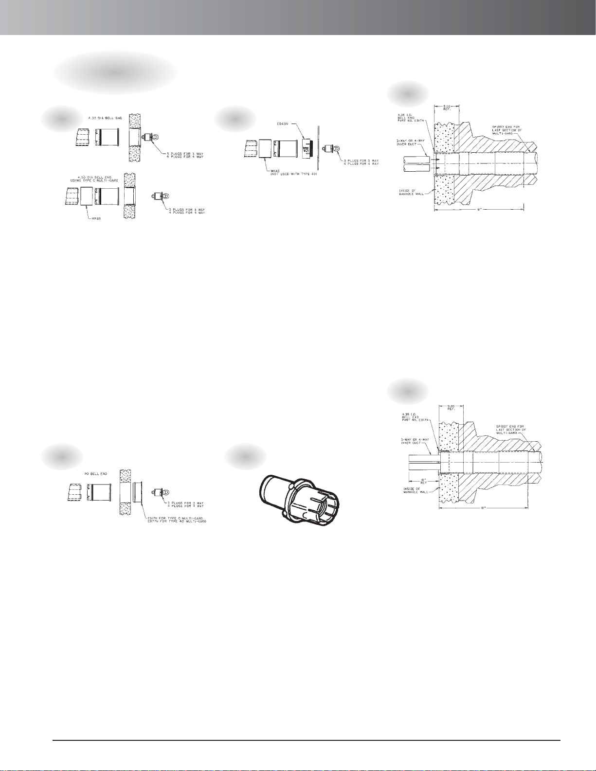
Multi-Gard®PVC – Terminations
Standard Terminators (Type 1) allow
Multi-Gard to be terminated into a
standard pre-cast termination.
1. Remove watertight plugs in order to
assure total insertion of the Multi-Gard
innerducts.
2. Install terminators into male end of
Multi-Gard to full depth.
3. Replace watertight plugs into the
terminator and tighten.
4. Insert prepared male end into the
pre-cast terminator with print line facing
upward. Solvent cement into place.
5. Use shim enclosed for terminator
requiring a connection of Type C
(4.35 O.D.) into a Type 40 (4.50 O.D.)
termination.
Use a Type 6 Enclosure Terminator at
entrances into metal or non-metallic
enclosures above ground.
1. Remove watertight plugs in order to
assure total insertion of the Multi-Gard
innerducts.
2. Install terminators into male end of
Multi-Gard to full depth.
3. Replace watertight plugs into the
terminator and tighten.
4. Install threaded adapter over end of
Multi-Gard using solvent cement. Insert
adapter through enclosure hole and
provide 4" locking ring.
5. Use shim enclosed for terminator
requiring a connection of type C (4.35
O.D.) termination.
The pass-through terminator is designed to
allow for continuous ducts through the vault
or hand hole for cable pulling.
1. Install terminator into vault following steps
1 through 5 for standard Type 1 terminator.
2. Cut innerduct of pass through kit 10" longer
than the width of the manhole. Add spacers
as needed.
3. Upon completion, remove the watertight
plugs and install innerducts to traverse
manhole/handhole by cutting to length
inserting into one side of handhole and
raising or bowing center of innerduct span
to insert into the pass-through terminator
on the opposite side. (See pass-through kits
on page 276.)
Use a Type 1 Standard Terminator also at an
entrance where a pre-cast terminator is not
available or a knockout is used:
1. Insert the male end section of Multi-Gard
4 inches past the inside wall of the vault
with print line facing upward.
2. Remove the protective cap from the male
end of the Multi-Gard.
3. Remove the watertight plugs and insert
the terminator to full depth.
4. Install bell fitting over the end of
Multi-Gard using solvent cement, and
replace plugs.
5. Slide Multi-Gard section until bell fitting is
flush with inside, and then seal entrance as
required by job specifications.
Use the jet terminator for jetting operations.
1. Remove watertight plugs in order to assure
to total insertion.
2. Apply standard grade solvent cement
(VC9962) to male end of Multi-Gard. Install
jet terminator to insertion line.
3. Replace watertight plugs into terminator
and tighten.
4. Apply standard grade solvent cement to
terminator male end and insert into pre-cast
bell end. (Install PVC bell fitting in kit if precast bell end is not available).
5. Use shim enclosed for terminator requiring
a connection of Type C (4.35" O.D.) into a
Type 40 (4.50" O.D.) termination.
6. Measure between ends of terminators on
opposite ends of vault, and cut innerduct to
length.
7. Solvent cement each coupling into place or
use mechanical coupling rated for use with
high speed air blowing systems.
Use split plugs for sealing Multi-Gard cells
where cable has been installed.
(See page 274)
Terminations
1.
3.
5.
4.
2.
6.
Gross Automation (877) 268-3700 · www.carlonsales.com · sales@grossautomation.com
Page 3

www.carlonsales.com
8
Multi-Gard®PVC – Installation
All PVC Trenching installation allows
Multi-Gard to be placed in the trench
one section at a time or over the
trencher for continuous feed.
Open trenching with Type C Multi-Gard
is recommended for direct burial or
concrete encased applications.
• Install one section at a time.
• Multiple-cells are installed as soon
as product is placed.
• Economical installation with
installation speed as fast as the
trencher.
• Easy installation with standard
equipment.
• Gasketed coupling body prevents
conduit pulling apart during
installation.
• Industry standard outer duct in
Type C is suitable for direct burial.
• Schedule 40 outershell and
Schedule 80 outershell are
available where extra protection
is necessary.
• Spacers inside outershell allow
PVC innerduct internal movement
allowing for more flexibility.
Paved Areas In paved areas, the surface should be carefully
cut to prevent unnecessary excessive width at the top of the
trench and help reduce the amount of surface to be repaved.
Trench Width For economical operation, particularly where
paving is involved, the trench width should be no greater than is
needed to provide adequate working space. Generally, this
dimension is controlled by the types of excavating equipment
used. As a minimum, the trench must be 5 inches wider than the
width of the conduit structure where backfill will be used and 3
inches wider where concrete encasement will be used.
Individual job specifications will dictate trench width.
Trench Bed Grade and level the trench bed. Where necessary, provide sand and/or other granular backfill as bedding
material so the conduit will be evenly supported over the length
of each section.
Assembly On Top Of The Trench After preparing the
trench, the Multi-Gard can be assembled on top of the ground
outside of the trench by following the directions described on
page 5. Once joined together, the Multi-Gard can then be laid
gently into the trench. Backfill according to the job specifications.
Trench Feeding Multi-Gard Using Rollers This
procedure involves assembling the Multi-Gard above the
ground. After the first four or five lengths are assembled, place
on top of the trenching machine. The remainder of the duct can
be attached to the first section and assembled ahead of the
trencher on the ground directly above the intended place for the
trench. As the trencher advances forward, the Multi-Gard will
lay itself into the trench behind. Once placed in the trench,
backfill according to the job specification.
Trenching
Features Procedures
Gross Automation (877) 268-3700 · www.carlonsales.com · sales@grossautomation.com
Page 4

www.carlonsales.com
9
Multi-Gard®PVC – Repairs
Repairing Vacant Multi-Gard
Repairing Multi-Gard Containing Cable(s)
1. Cut out the damaged section
and insert a belled short section
(4" shorter than damaged
section) of Multi-Gard onto
either one of the ends (section A).
2. Apply 2" of cement on ends
of spigots of coupling body,
press couplings onto spigots.
3. Slide innerduct sleeve over
Multi-Gard plain end (section A).
Insert end spacer into MultiGard plain end (section B).
1.
Carefully cut out damaged section up to 10
feet. Larger sections can be accommodated
using multiple repair kits.
3.
Install corrugated innerduct and remaining
smooth innerduct into couplings by raising in
the center and guiding them into their respective openings. Install the spacers to evenly
support the innerduct.
4.
Lay one piece of split duct under the
repaired section. Install the other piece of split
duct onto the first piece and strap or tape in
place. Apply cement onto each end and slide
the slip sleeves until centered on both sections.
Backfill according to job specifications.
2.
Install the 4" split sleeve couplings over
the existing Multi-Gard. Slide the smaller split
couplings onto the individual innerduct, fitting
the cable into the split coupling. Repeat this
process on opposite side. Carefully insert the
cable(s) into the split corrugated innerduct.
4. Insert female end of slip coupling
into Multi-Gard plain end (section A).
Align sections A and B. Apply cement
to couplings. Slide slip coupling back
onto innerducts in Multi-Gard
(section B) until seated.
5. Apply cement to both
plain ends of Multi-Gard
and slide sleeve until
centered on both sections.
M SC4
–
Slip Coupling
Gross Automation (877) 268-3700 · www.carlonsales.com · sales@grossautomation.com
Page 5

www.carlonsales.com
10
Multi-Gard®PVC – Repair Kits
Repair Kits
Repairing Multi-Gard with Damaged Cables
E940F PVC Coupling
Couples PVC innerduct with solvent cement
for empty cells (standard grade qt. cement
#VC9962).
MAFPG7 Fiber Optic Simplex Plug
(cable O.D. range .57 - .65) Seals innerduct
with cable installed.
MAQPG2 Quadplex Plug (4 holes each)
Seals outershell and innerduct
1
2
3
4
5
Repair Kit Instructions:
1.
Dig around break area enough to allow vault to
drop over the repair area and rest level when the
mouseholes have been cut away for the duct.
2.
Cut away and remove outer shell and any
damaged inner-ducts, being careful to protect
any exposed cables.
3.
Cut back the outer duct to allow approximately
6
"
of inner-duct exposed.
4.
Install the splice case per manufacturer’s or
customer’s specifications, allowing enough cable
slack so no tension is felt.
2
1
3
4
1
3
2
5
6
6
48808DK PVC Pass-through Kit
(4 x 20' lengths) 20 foot lengths can be cut to
length for continuous empty innerduct.
Underground Vault & Lid needed
Choose size & construction based on dimensions
of splice cases and weight requirements. (Allow
12" on either side of splice for bending
innerduct)
Splice Case
5.
Install the quad plugs (Item #3) and single
plugs (Item #2) in duct containing cable.
6.
Install pass-through ducts (Item #4) with
coupling (Item #1) sealing with solvent cement.
7.
Set the enclosure base over the entire package
and place cover on enclosure.
8.
Refill hole as required.
Gross Automation (877) 268-3700 · www.carlonsales.com · sales@grossautomation.com
 Loading...