

Page 1
ENCLOSED YOU
WILL FIND:
• Floor Box
• Hole Saw
• Wired receptacle
• Optional mounting plates
• Mounting screws
• Wire nuts
Caution: Follow all national and local electrical codes for this
installation. Before installation of the drop-in floor box, disconnect
the AC power to any wiring intended to power this product.
Determine the location in the floor for the installation of the floor box.
Make sure that under this floor location there are no pipes or
electrical wiring that could be damaged by the installation. There
must be at least 7” of clearance below the bottom of the sub flooring
in order to allow installation of the floor box.
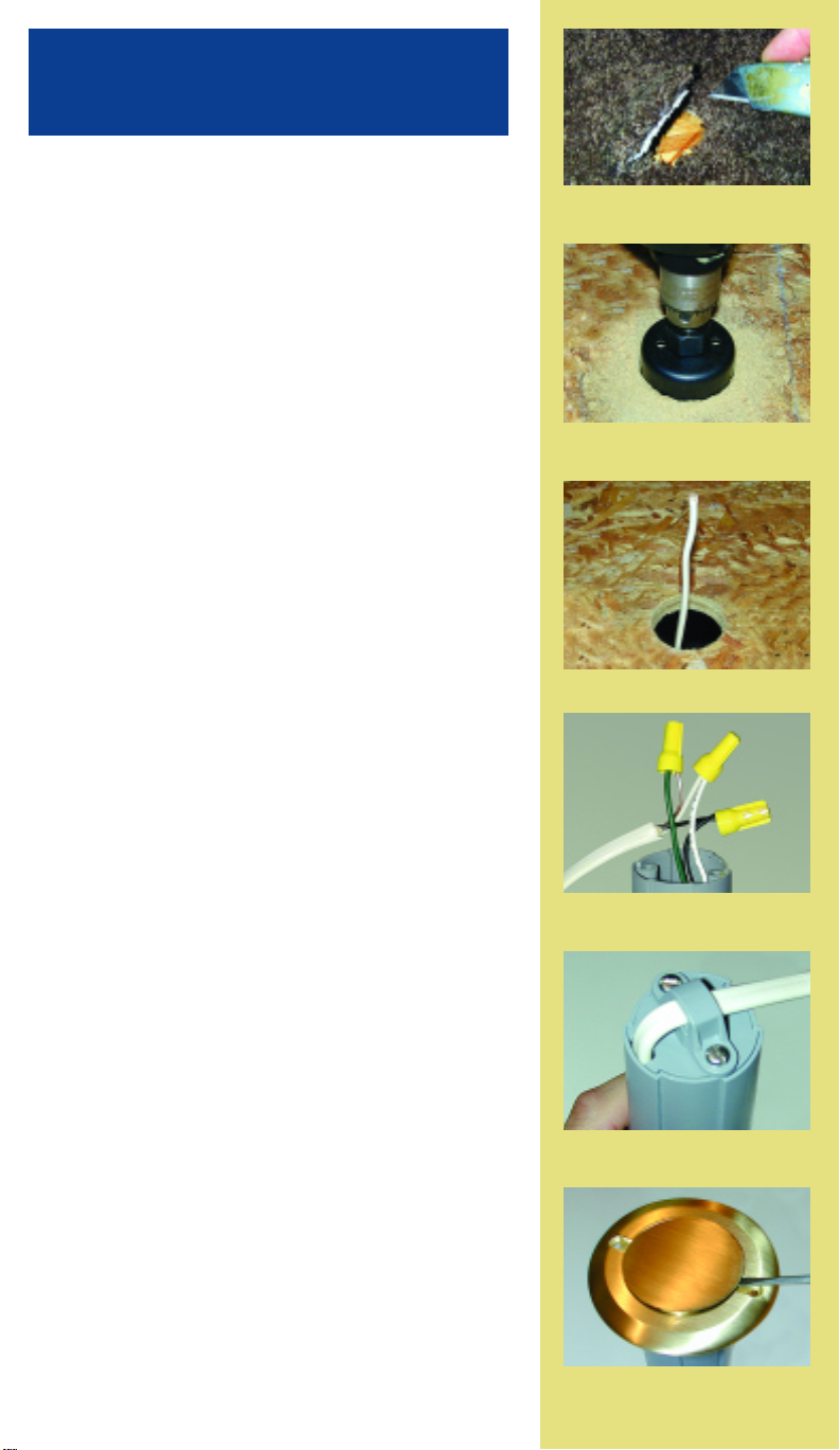
Mark the center of the floor box location on the top of the floor. If the
floor is carpeted, first cut a 2-3/8’’ diameter hole through the carpet
with a sharp utility knife (see Figure 1). See enclosed template.
Caution: Using the hole saw provided to cut through the carpet
could result in a snag causing permanent damage to the carpet.
Never drill a hole through carpeting.
Position the hole saw pilot drill (provided) at the center of the location
for the floor box. Drill through the flooring with the hole saw (see
Figure 2).
With the brass cover positioned upside down over the hole in the
floor, use the cover as a template and mark the two cover screw
locations, with a pencil, on the flooring. Before drilling a 3/32”
diameter pilot hole for each cover screw, push aside any carpeting so
the drill does not go through the carpet.
FOR THE INSTALLATION OF THE
SINGLE RECEPTACLE:
1. Pull the new romex type wire for the receptacle up through the
hole in the flooring (see Figure 3).
2. Remove the floor box bottom cover and cable clamp. Save
the screws.
3. Pull out from the bottom of the floor box the three wires (white,
black, green) from the receptacle.
4. Using the provided three wire nuts, connect the power supply
romex (#14 or #12) wires to the receptacle wires, keeping the same
colored wires together (black to black, white to white, green to
green, see Figure 4).
5. Push the excess wires into the floor box and allow the romex to
exit through the opening in the bottom cover plate. Re-install the
bottom cover plate and clamp using the screws provided. The
clamp is placed over the romex as it is bent across the bottom of
the floor box (see Figure 5).
6. Apply a bead of caulking to the top edge of the hole in the floor.
Drop the completed floor box assembly into the hole in the floor.
Using the two brass screws provided, screw the brass cover plate
down to the sub flooring.
7. For use of the receptacle, remove the brass circular cover by prying
open with a small screwdriver (see Figure 6). Plug a lamp or small
appliance (120 VAC, 15 amps or less) into the single receptacle.
INSTALLATION INSTRUCTIONS
Drop-In Floor Box E971FBDI
Figure 1 - Cut 2-3/8’’ hole through
carpeting before using hole saw.
Figure 2 - Drill hole in floor using
hole saw.
Figure 3 - Pull romex through floor.
Figure 4 - Connect receptacle wires to
romex. Be sure to match wire color(s).
Figure 5 - Secure wire clamp on
bottom of tube.
TOOLS NEEDED:
• Power Drill
• Flat head screwdriver
• Phillips head screwdriver
• Utility Knife
• Latex Caulking
Figure 6 - Brass cover snaps into place.
Use a small screwdriver to pry open
brass cover to plug in appliance.
Page 2
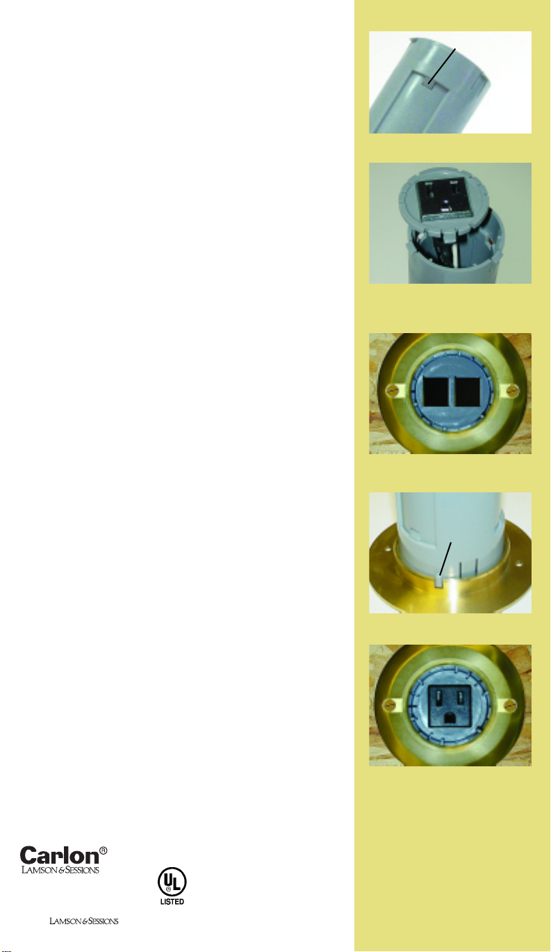
View of communications cover in place.
(Low voltage jacks are not included.)
120V AC, 60 Hz
15 Amps Max.
25701 Science Park Drive
Cleveland, Ohio 44122
www.lamson-sessions.com
Made in China
©2004
0402 IS154
Non-Metallic
Outlet Box
655A
Non-Metallic
Outlet Box
655A
Completed floor box with receptacle
recessed into tube.
Figure 7
Figure 9
FOR FLOOR BOX AND LOW VOLTAGE DEVICE
PLATE INSTALLATION:
1. Remove the brass cover from the floor box by pressing inward on
the three latches on the side of the box and pulling the cover
upwards.
2. Push inward on the three latches (see Figure 7) that hold the
receptacle plate in place and remove the receptacle and plate
(see Figure 8).
3. Install the appropriate low voltage wiring jacks (not included) into
the low voltage plate.
4. Pull the low voltage cables up through the hole in the flooring (see
single receptacle instructions) and connect to the jacks.
5. Align the three latches on the low voltage plate with the three latch
holes in the round floor box tube (see Figure 7). While aligning the
low voltage plate slots with the ribs on the inside of the round floor
box tube, push the low voltage plate back into the round floor box
tube until the three latches snap into the three latch holes in the
side of the tube. It may require extra force to push the low voltage
plate all the way down to the latch point. The low voltage plate is
made with a tough polycarbonate material and should not break
from push-in forces.
6. Snap the round floor box tube back into the bottom of the brass
cover. Make sure that one of the slots on the brass cover rim lines
up with the rectangular plastic bump on the outer surface of the
round floor box tube (see Figure 9).
7. Apply a bead of caulking to the top edge of the hole in the floor.
Drop the completed floor box assembly into the hole in the floor.
Using the two brass screws provided, screw the brass cover plate
down to the sub flooring.
8. Remove the brass circular cover by prying open with a small
screwdriver. Plug in the low voltage cable(s) into the jack(s).
One of the three
latch holes on
floor box tube.
Rectangular
plastic bump
aligned with
brass cover slot.
Figure 8 - Remove receptacle by
pressing three tabs located on side
of tube.
 Loading...