

Carlon CS863, CS12106, CS665, CS14126, CS1085 Installation Instructions And Accessory Applications
...Page 1
®
Installation Instructions
and Accessory Applications
English
Mounting Feet:
This enclosure is shipped with its mounting brackets and
installation screws packaged inside. Bracket design permits this
enclosure mounted with major dimension vertical. The purchase
of mounting feet (Part No. CJB 159) permits this enclosure to
be mounted with the major dimension horizontal to the ground.
(Cut out style only.) Use athead screw (1/4-20x1/2”) to secure
brackets to enclosure. Securely tightening the mounting brackets
will insure positive positioning of the enclosure. Torque limits for
these athead screws are 50 in-lbs (maximum).
Covers:
The fastenings for the cover are captive slotted stainless steel
lister head screws (10-32), which are factory installed. The
torqued down limits for these screws are 25 in-lbs (maximum).
Installation of Conduit:
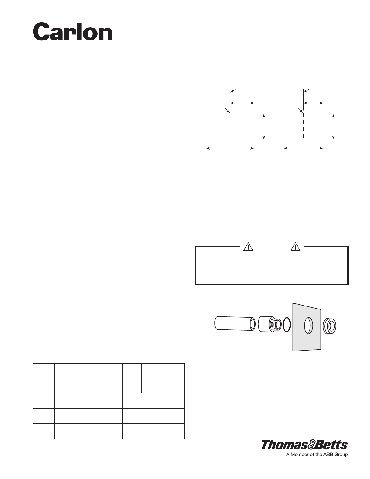
1) CONDUIT HOLES:
Cut holes in enclosure (when required) at the desired location.
The use of a standard hole saw is the preferred method.
For proper location of hubs, prepare a paper template with
the recommended B x C (End Installation) or A x C (Side
Installation) dimensions. Reference the table below for the
specic enclosure size. Position a standard hole saw anywhere
within the rectangle and drill (care should be taken to prevent
damaging the bosses). The maximum hub and hole size varies
with the size of the enclosure.
Reference point F should always be centered midway
between the bosses.
For side installation on hinge models, hinge side, conduit holes
should be positioned a minimum of 1” from bottom of hinge
assembly. All other dimensions are the same as on hingeless
models.
C Series Enclosures do not have the same conduit placement
requirements. It is recommended that hole locations be
centered on the sides a minimum of 1-1/2” from the bottom
and 2-1/2” from the top.
TEMPLATE DIMENSIONS FOR LOCATION
OF ELECTRICAL FITTING IN CUTOUT BOXES
PS, PJ, CS, CJ, CV & CC MODELS
Catalog
Number
CS665 6x6x5-3/4 5-1/4 2-3/4 2-1/4 1-1/2 1-1/2
CS863 8x6x3-1/2 7-1/8 2-3/4 1-5/8 1-1/2 1-1/2
CS1085 10x8x5-3/4 4 4-3/4 2-1/4 1-1/2 1-1/2
CS12106 12x10x6-3/4 4-3/4 6-3/4 3-3/4 2-1/2 2-1/2
CS14126 14x12x6-3/4 6 8-3/4 4-1/2 3-1/2 3-1/2
CS16147 16x14x7-1/2 6-3/4 10-3/4 4-1/2 3-1/2 3-1/2
Inside Box
Size
Side
Installa-
tion
A
End
Installa-
tion
B C
Long
Side
Max.
Conduit
Size
Short
Side
Max.
Conduit
Size
Line up with scribe
Line on “TOP” or “BOTTOM”
of box.
1/2
F F
Figure 1
B
B A
C C
Line up with scribe
Line on side of box.
1/2
A
2) CONDUIT CONNECTIONS:
a. Metallic Conduit:
1. Secure the conduit connector (hub) onto the conduit, as
the hub shall be connected to the conduit BEFORE the
hub is connected to the enclosure.
2. Secure conduit connector (hub) into the prepared
enclosure hole using the connector locknut.
3. Attach grounding bushing having the proper size ground
wire lug over the connector locknut.
CAUTION
In accordance with the National Electrical Code, the
enclosure must be bonded between the grounding
bushings or between the grounding bushings and
the equipment grounding terminal (when provided).
Carlon Watertight Hubs
(See Hub Section)
Figure 2
b. Nonmetallic Conduit (see illustration above): Secure
conduit to the conduit connector (hub), and the
hub shall be connected to the conduit BEFORE the
hub is connected to the enclosure, then secured
into the prepared hole using the connector locknut.
NOTE: Ground bushing not required when
attaching to nonmetallic conduit.
TA04617 C Page 1 of 4
Page 2

CAUTION
To prevent enclosure damage and attain the enclosure
requirements, the conduit should be aligned so as to
prevent unnecessary stress on the enclosure walls.
To obtain maximum corrosion protection, with
metallic conduit and hub assemblies, cover (coat)
all exposed metal and seal off the conduit openings
where the conductors enter the enclosures.
Grounding of Equipment:
Install the grounding conductor in accordance with the
requirements of the National Electrical Code. See illustrations
below for metallic and nonmetallic conduit.
Hubs:
For metallic conduit application the use of a Listed Hub and
Grounding Bushing System is required.
For nonmetallic conduit application, use Carlon’s male adapter
(sizes E943 through E943R) and “O” ring (sizes E943DX through
E943RX) with bushing (sizes E943DY through E943RY).
Hinge Caps (included):
Metallic Conduit NonMetallic Conduit
CONNECTOR LOCKNUT
GROUNDING BUSHING
GROUNDING CONDUCTOR
EQUIPMENT
GROUNDING
TERMINAL
(WHEN PROVIDED)
Figure 3
Figure 4
Catalog Number CH 100R, have been added to the design
to reduce dirt and dust accumulation in the hinge pin and lid
assembly.
To position the hinge caps, align the snap tang and push.
To remove hinge caps, insert a point (such as a pencil) in the
lid hinge section and push the pencil point toward the side
of the enclosure. This will permit the snap tang to clear the
molded interference. Then pull the hinge cap from the slot.
EXTERIOR PAINTING OR FINISHING – PLEASE CONTACT THOMAS & BETTS FOR LIST OF
APPROVED FINISHING SYSTEMS.
NOTE: Enclosure drilled for conduit or other fabrication steps may NOT be returned for credit.
WARRANTY: Thomas & Betts sells this product with the understanding that the user will perform all necessary tests to
determine the suitability of this product for the user’s intended application. Thomas & Betts warrants that this product will
be free from defects in materials and workmanship for a period of two (2) years following the date of purchase. Upon prompt
notication of any warranted defect, Thomas & Betts will, at its option, repair or replace the defective product or refund the
purchase price. Proof of purchase is required. Misuse or unauthorized modication of the product voids all warranties.
Limitations and Exclusions: THE ABOVE WARRANTY IS THE SOLE WARRANTY CONCERNING THIS PRODUCT, AND
IS IN LIEU OF ALL OTHER WARRANTIES EXPRESS OR IMPLIED, INCLUDING BUT NOT LIMITED TO ANY IMPLIED
WARRANTY OF MERCHANTABILITY OR FITNESS FOR A PARTICULAR PURPOSE, WHICH ARE SPECIFICALLY
DISCLAIMED. LIABILITY FOR BREACH OF THE ABOVE WARRANTY IS LIMITED TO COST OF REPAIR OR
REPLACEMENT OF THE PRODUCT, AND UNDER NO CIRCUMSTANCES WILL THOMAS & BETTS BE LIABLE FOR
ANY INDIRECT, SPECIAL, INCIDENTAL OR CONSEQUENTIAL DAMAGES.
Thomas & Betts Corporation
Memphis, Tennessee
TA04617 C Page 2 of 4
www.tnb.com
© 2017 Thomas & Betts All Rights Reserved.
Page 3

MD
Directives d'installation
et utilisations d'accessoires
Français
Pattes de fixation:
Ce boîtier est livré avec ses brides de xation et ses vis de montage
emballées à l'intérieur. La conception des brides permet à ce boîtier
d'être monté à la verticale. L'achat de pattes de xation (Pièce No.
CJB 159) permet à ce boîtier d'être monté à l'horizontale (style
disjoncteur uniquement.). Utiliser la vis à tête plate (1/4-20x1/2po)
pour xer les brides au boîtier. Bien serrer les brides de xation
assurera la bonne mise en place du boîtier. Les limites de couple
pour ces vis à tête plate sont 50po-lb (maximum).
Couvercles:
Les attaches pour le couvercle sont des vis fendues imperdables
à tête cylindrique bombée (10-32), posées en usine. Les limites de
couple pour ces vis sont 25po-lb.
Installation du conduit:
1) TROUS POUR LE CONDUIT:
Découper des trous dans le boîtier (s'il y a lieu) à l'emplacement
choisi. L'utilisation d'une scie-cloche standard est la méthode
préférée.
Pour choisir le bon emplacement des emboîtements, préparer
un gabarit en papier avec les dimensions recommandées B x
C (Installation en extrémité) ou A x C (Installation latérale). Se
reporter au tableau ci-dessous pour la taille spécique du boîtier.
Placer une scie-cloche standard n'importe où dans le rectangle et
percer (il faut faire attention à ne pas endommager les bossages).
La taille maximale de l'emboîtement et du trou varie en fonction de
la taille du boîtier.
Le point F de référence doit toujours être centré au milieu des
bossages.
Pour l'installation latérale sur les modèles à charnières, côté
charnière, les trous du conduit doivent être situés à plus de 1po
du bas des charnières. Toutes les autres dimensions sont les
mêmes que sur les modèles sans charnières.
Les boîtiers de série C n'ont pas les mêmes exigences de
placement de conduit. Il est recommandé que l'emplacement
des trous soit centré sur les côtés à plus de 1-1/2po du bas et
2-1/2po du haut.
DIMENSIONS DU GABARIT POUR L'EMPLACEMENT
DE RACCORD ÉLECTRIQUE DANS DES BOÎTES DE DISJONCTEUR
MODÈLES PS, PJ, CS, CJ, CV ET CC
Numéro
de cata-
logue
CS665 6x6x5-3/4 5-1/4 2-3/4 2-1/4 1-1/2 1-1/2
CS863 8x6x3-1/2 7-1/8 2-3/4 1-5/8 1-1/2 1-1/2
CS1085 10x8x5-3/4 4 4-3/4 2-1/4 1-1/2 1-1/2
CS12106 12x10x6-3/4 4-3/4 6-3/4 3-3/4 2-1/2 2-1/2
CS14126 14x12x6-3/4 6 8-3/4 4-1/2 3-1/2 3-1/2
CS16147 16x14x7-1/2 6-3/4 10-3/4 4-1/2 3-1/2 3-1/2
Taille inté-
rieure de
la boîte
Instal-
lation
latérale
Installa-
tion en
extré-
A
mité
B
Taille
max du
conduit,
long
C
côté
Taille
max du
conduit,
petit
côté
Aligner avec la ligne
Ligne au dessus ou au
dessous de la boîte
1/2
F F
Figure 1
B
B A
C C
Aligner avec la ligne
Ligne sur le côté
de la boîte
1/2
A
2) RACCORDEMENTS DES CONDUITS:
a. Conduit métallique
1. Fixer le raccord de conduit (emboîtement) au conduit
parce que l’emboîtement sera connecté au conduit
AVANT que l’emboîtement soit connecté au boîtier.
2. Fixer le raccord de conduit (emboîtement) dans le trou
préparé du boîtier à l'aide de l'écrou autobloquant du
raccord.
3. Fixer l'embout de mise à la terre à l'aide de la cosse
du l de mise à la terre sur l'écrou autobloquant du
raccord.
ATTENTION
Selon le National Electrical Code, le boîtier doit
être lié à la terre entre les embouts de mise à la
terre ou entre ceux-ci et la borne de mise à la
terre de l'équipement (s'il y a lieu)
Emboîtements étanches de Carlon
(Voir la section emboîtement)
Figure 2
b. Conduit non métallique (voir illustration ci-dessus):
Fixer le conduit au raccord de conduit (emboîtement)
et l’emboîtement sera connecté AVANT que
l’emboîtement ne soit connecté au boîtier et ensuite xé
dans le trou préparé en utilisant l’écrou autobloquant du
raccord.
NOTE: Embout de mise à la terre non obligatoire lors de
la xation d’un conduit non métallique.
TA04617 C Page 3 of 4
Page 4

ATTENTION
Pour éviter d'endommager le boîtier et pour atteindre les
exigences du boîtier, le conduit doit être aligné afin de
prévenir des contraintes inutiles sur les parois du boîtier.
Afin d'obtenir une protection maximale contre la corrosion,
avec les ensembles conduit et emboîtement métalliques,
recouvrir (couche) toutes les parties métalliques exposées
et sceller les ouvertures de conduit là où les conducteurs
pénètrent dans les boîtiers.
Mise à la terre de l'équipement:
Installer le conducteur de mise à la terre selon les
exigences du Code national de l'électricité. Consulter
les illustrations ci-dessous lors de l'utilisation d'un
conduit métallique ou non métallique.
Emboîtements:
Pour les conduits métalliques, l'utilisation d'un système homologué
d'embout et d'emboîtement de mise à la terre est exigée.
Pour les conduits métalliques, utiliser un adaptateur mâle Carlon
(tailles E943 à E943R) et un joint torique (tailles E943DX à E943RX)
avec un embout (tailles E943DY à E943RY).
Figure 4
Conduit métallique Conduit non-métallique
CONTRE-ÉCROU
Capuchons de charnière (fournis):
Numéro de catalogue CH 100R, ont été ajoutés à la conception an
de réduire l'accumulation de saleté et de poussière dans l'ensemble
MANCHON DE MISE À
LA TERRE
CONDUCTEUR DE MISE
À LA TERRE
ÉQUIPEMENT DU
TERMINAL DE MISE À LA TERRE
(LORSQUE FOURNI)
Figure 3
axe de charnière/couvercle.
Pour poser les capuchons, aligner le tenon à pression et pousser.
Pour retirer les capuchons, insérer une pointe (comme un crayon)
dans la section de la charnière du couvercle et pousser la pointe
avec le côté du boîtier. Cela permettra de dégager le tenon à
pression. Puis retirer le capuchon de charnière de la fente.
PEINTURE OU FINITION EXTÉRIEURE – VEUILLEZ COMMUNIQUER AVEC THOMAS & BETTS
POUR OBTENIR UNE LISTE DES SYSTÈMES DE FINITION APPROUVÉS.
NOTE: les boîtiers percés pour le passage de conduit ou autres étapes de fabrication NE doivent PAS être
retournés pour être crédités.
GARANTIE: Thomas & Betts vend ce produit à condition que l’utilisateur se charge des tests nécessaires pour déterminer
si le produit convient à l’application qu’il veut en faire. Thomas & Betts garantit que ses produits sont libres de vices de
matériaux et de fabrication pour une période de deux (2) ans de la date d’achat. Sur avis donné promptement de tout défaut
couvert par cette garantie, Thomas & Betts se réserve le choix de réparer ou de remplacer le produit défectueux ou d’en
rembourser le prix d’achat. L’avis doit être accompagné d’une preuve d’achat. Si l’outil est soumis à un mauvais usage ou s’il
fait l’objet d’une modication non autorisée, cette garantie devient nulle et non avenue.
Limitations et exclusions: CETTE GARANTIE EST LA SEULE GARANTIE VALABLE POUR CE PRODUIT. ELLE REMPLACE
TOUTE AUTRE GARANTIE, EXPRESSE OU TACITE, Y COMPRIS MAIS SANS S’Y LIMITER, TOUTE GARANTIE TACITE DE QUALITÉ
MARCHANDE OU DE CONFORMITÉ À L’USAGE AUQUEL IL EST DESTINÉ. LA SEULE RESPONSABILITÉ POUR RUPTURE DE
GARANTIE EST LIMITÉE AU COÛT DE RÉPARATION OU DE REMPLACEMENT DU PRODUIT ET THOMAS & BETTS NE POURRA, EN
AUCUN CAS, ÊTRE TENU RESPONSABLE DE DOMMAGES FORTUITS, DIRECTS OU INDIRECTS
Thomas & Betts Corporation
Memphis, Tennessee
TA04617 C Page 4 of 4
www.tnb.com
© 2017 Thomas & Betts Tous droits réservés.
 Loading...