

Carlo Gavazzi Logistics RAD02, RAD01 User Manual
User Manual
Motion Sensor
RAD
Safety Notes
Motion Sensor Radar is a digital uni or bidirectional motion
sensor for trouble-free opening of all types of automatic doors
(sliding, swinging, folding, revolving, speed-doors, overhead
doors, etc...), for pedestrian and civil applications.
It can be adapted to every application without further
accessories and can be controlled by an infrared remote
controller. Mounting height up to 4m (13.12ft) also available in
ni- or bidirectional mode to detect motion towards or away from
u
the device. Like most of other microwave detectors, equipped
with planar flat antenna, Carlo Gavazzi Radar activates automatic
doors utilizing doppler shift effect for detecting movements.
Read Instructions!
Before working with this unit,
read these instructions carefully
and completely. Make sure that
you have understood all the
information!
Disconnect system from
supply network
Before any installation,
maintenance or modification
work:
Disconnect your system from
the supply network. Ensure that
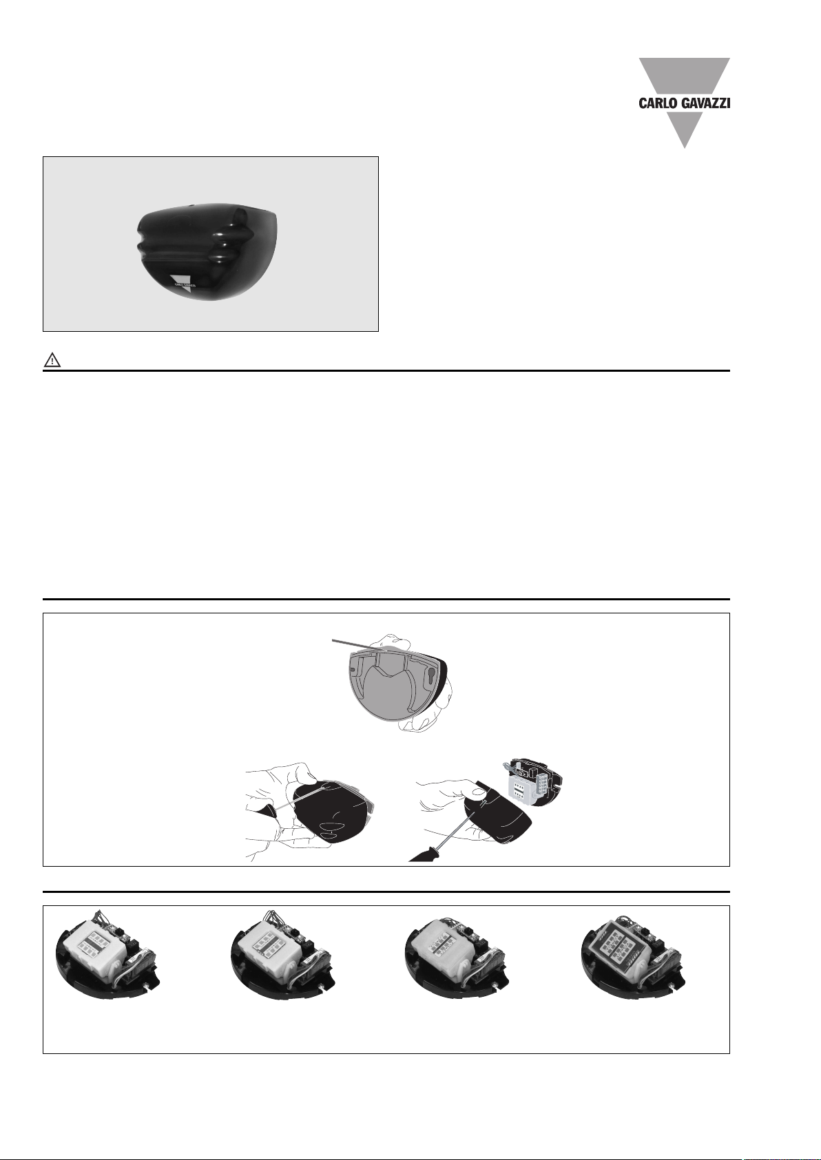
Cover Removing
After installation from the front side, insert the screwdriver in the provided slot.
cannot be re-connected
inadvertently!
Before start of operation
ensure appropriate installation
Warning! Improper installation /
operation impair safety and
result in operational difficulties or
complete failure of the unit.
The unit must be installed and
put into service appropriately by
qualified personnel. Compliance
with the relevant regulations
must be ensured.
Remove cover from behind, before installation.
With stranded wires: all strands
must be secured in the terminal
blocks (potential danger of short
circuit).
In operation: No modifications!
As long as the unit is in
operation: do not modify the
installation! The same applies
also to the secondary side.
• The unit must not be opened
except appropriately trained
personnel!
• Do not introduce any object
into the unit!
• Keep away from fire and water!
FCC warnings
This device complies with Part
15 of the FCC Rules. Operation
is subject to the following two
conditions:
1) this device may not cause
harmful interference, and
2) this device must accept any
interference received, including
interference that may cause
undesired operation.
Inside View
RAD 01 To obtain narrow
pattern L2 install the planar
antenna in horizontal mode.
© Copyright – Carlo Gavazzi - All rights reserved
This manual accompanies our equipment for use by the end users.
The technical instructions and illustrations contained in this manual are to be treated as confidential and no part may be reproduced without the prior written permission of Carlo Gavazzi
Service engineers and end users may not divulge the information contained herein or use this manual for purposes other than those strictly connected with correct use of the equipment.
Specifications are subject to change without notice. Pictures are just an example.
RAD 01 To obtain wide
pattern L1 install the planar
antenna in vertical mode.
1 Specifications are subject to change without notice.Pictures are just an example. For special features and/or customization, please ask to our sales network.
RAD 02 To obtain wide
pattern L3 or L5 install the
planar antenna with tie clip.
RAD 02 To obtain narrow
pattern L4 or L6 install planar
antenna without tie clip.

Installation Tips
E
XI
T
Fix firmly radar sensor
to the wall.
Avoid the presence of
moving objects in radar
sensing field.
Not install panels or
metallic surfaces close
to the device.
Not install radar on
direct exposure of
rain.
Not install radar close to
fluorescent lamp.
Mounting Template mm (inches) Mounting Instructions
Ceiling
Cable inlet
o install radar is necessary only a screwdriver and drill.
T
Wall mounting. Ceiling mounting.
Detection Area Shape modifying instructions
To adjust the type of the sensing field and pattern, verify the following instructions:
RAD 01 To obtain wide pattern install the planar antenna in vertical mode, while to obtain narrow pattern install the planar antenna
in horizontal mode. Carefully remove the fixing tie clip with a screwdriver and change the orientation mode of planar antenna.
123
4
5
RAD 02 To obtain wide pattern install the planar antenna with tie clip. To obtain narrow pattern install planar antenna
without tie clip. Carefully use a screwdriver to remove the sensing field setting tie clip, when is necessary.
1
CAUTION!
Power off the radar before removing the planar antenna.
The radar is an electrostatic sensitive device: proceed with caution to remove the planar antenna,
don’t wear synthetic clothes or rubber sole shoes.
Specifications are subject to change without notice.Pictures are just an example. For special features and/or customization, please ask to our sales network. 2
23
Electrical Connections
0.5
1.0
1.5
2.0
2.5
3.0
m
00.50.5 1.01.0 1.51.5 2.02.0 2.52.5 3.03.0 0m
S2
S4
S6
S10
S8
S
1.64
3.28
4.92
6.56
8.2
0
9.8
4
ft
0
1.64
1.64
3.28
3.28
4.92
4.92
6.5
6
6.56
8.2
0
8.20
9.8
4
9.84
ft
0.5
1.5
2.5
3.5
4.5
m
00.50.5 1.01.0 1.51.5 2.02.0 2.52.5 3.03.0
m
S4
S6
S8
S10
1.64
4.92
8.20
11
.48
14
.
76
ft
0
1
.
6
4
1
.
6
4
3
.
2
8
3
.
2
8
4
.
9
2
4
.
9
2
6
.
5
6
6
.
5
6
8
.
2
0
8
.
2
0
9
.
8
4
f
t
9
.
8
4
L1 L2 L3 L4 L5 L6
L2 L3 L4 L5 L6
Sensing Field adjustment
Mechanical sensor orientation
Push Button
DEC (-)
Push Button
INC (+)
Planar Antenna
ed LED IR Receiver Green LED
R
lanar antenna
P
ertical angle
v
5° 15°
4
ain Connector
M
Relay NO contact
Relay NC contact
elay Common Contact
R
12 to 24 VAC/DC
12 to 24 VAC/DC
Caution:
Power on the radar by Class2
or LVE transformer.
Do not power on the radar until
all primary and secondary
wiring is completed.
lanar antenna
P
ertical angle
v
Adjust the vertical position to obtain the vertical sensing field close or far from the door.
Lateral angle rotation -15° Lateral angle rotation 0° Lateral angle rotation 15°
Adjust the lateral position to obtain the desired lateral angle sensing field.
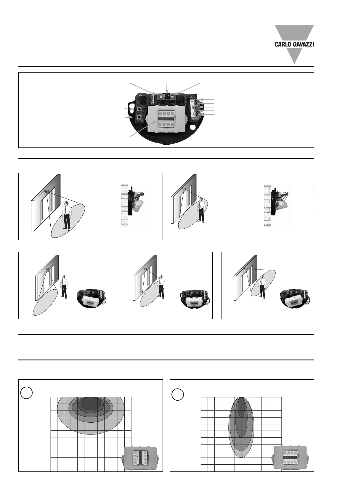
Sensing field adjustment according to Sensitivity setting and mounting Height
The sensing field area size (lobo) depends on the sensitivity parameter setting and the radar mounting height.
RAD 01 Bidirectional Model
Detection area vs Sensitivity value (vertical angle 45°);
vertical mount mode.
3 Specifications are subject to change without notice.Pictures are just an example. For special features and/or customization, please ask to our sales network.
h = 7.22ft
h = 2.2m
Detection area vs Sensitivity value (vertical angle 45°);
horizontal mount mode.
h = 7.22ft
h = 2.2m
 Loading...