

Page 1
T2000 SERIES
CARLO GAVAZZI
Automation Components
PID TEMPERATURE
CONTROLLER
English Français Deutsch Italiano Español
Page 2
INDEX INSTRUMENT PANEL FEATURES
FUNCTIONS MENU 3
GETTING STARTED 4
Initial Set-up 4
AUTOTUNE 4
Tune or tune at setpoint program 5
PROPORTIONAL CYCLE-TIME 5
Cycle-time recommendations 5
PROGRAMMER 5
Ramp-Soak 5
SECOND SETPOINT (SP2) 6
Error messages 6
FUNCTION LIST 7
Level 1 7
Level 2 7
Level 3 8
Level 4 9
MECHANICAL INSTALLATION 9
DIN panel cut-out 9
Mounting 9
Cleaning 9
ELECTRICAL INSTALLATION 10
Sensor selection 11
SPECIFICATION 11
SAFETY AND WARRANTY 12
2
Green Display: Process temperature or program Function/Option
Orange Display: Setpoint temperature or program Option (T20162 only)
Green LED: Setpoint 1 output indicator
Red/Orange LED: Setpoint 2 output indicator
ADJUSTMENTS
To enter or exit program mode: Press ▲ ▼ together for 3 seconds
To scroll through functions: Press ▲ or ▼
To change levels or options: Press ✱ ▲ together or ✱ ▼ together
To view setpoint: Press ✱
To increase setpoint: Press ✱ ▲ together
To decrease setpoint: Press ✱ ▼ together
To reset an alarm or fault condition: Press ▲ ▼ together briefly
Notes: If in difficulty by becoming “lost” in program mode, press ▲ and ▼ together for 3
seconds to return to display mode, check the INSTRUMENT ADJUSTMENTS above and
try again.
When in program mode, after 60 seconds of key inactivity the display will revert to
either inPt : nonE or, if the initial configuration has been completed, the measured
value. Any settings already completed will be retained.
This page can be photocopied and
used as a visual aid and bookmark when
working in other parts of the manual.
!
English
Page 3
3
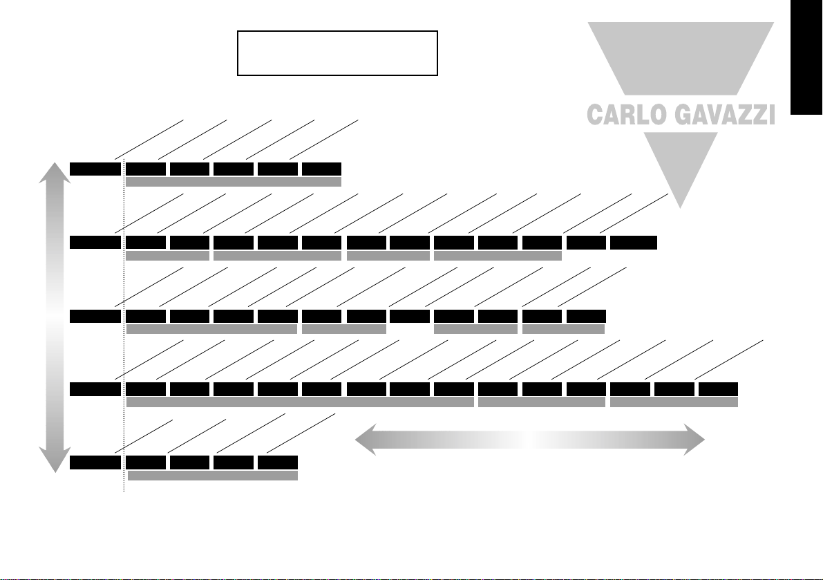
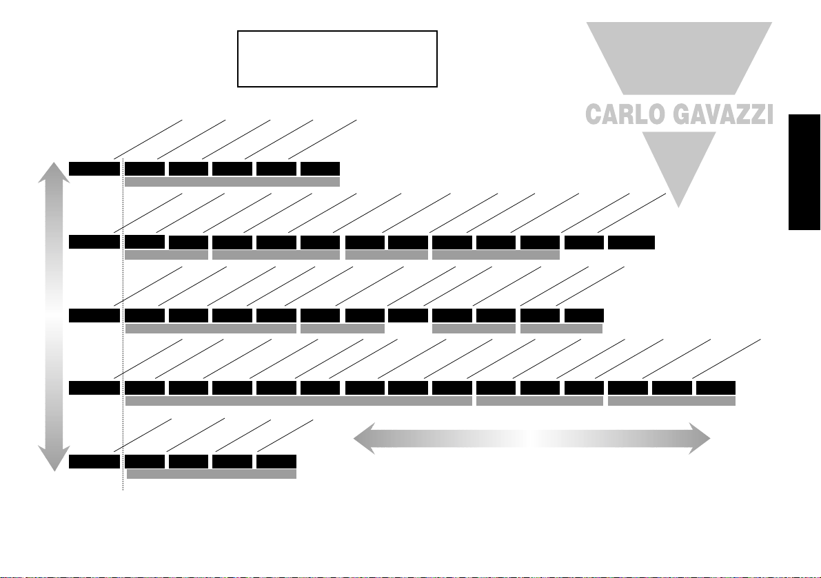
FUNCTIONS MENU
Range of Adjustment shown under description.
If applicable, factory settings shown in bold.
Note: The letter K appears in the instrument display
as the character K
BAND INT.T DER.T DAC CYC.T OFST SP.LK SPRR SPRN SOAK SET.2 BND.2 CYC.2
LEVL 1
TUNE
Autotune or Park
oFF; on; ParK; At.Sp
SP1 Prop band (gain)/hyst
0.1 deg to 25%
sensor f/s
(10°C/18°F)
Integral time (reset)
Off; 0.1 to 60 min (5 m
in
)
Derivative tim
e (rate)
Off; 1 to 200 sec (25 sec)
Derivative approach
0.5 to 5.0 x bAnd (1.5)
Cycle tim
e or on/off
O
n.off; 0.1 to 81 sec
(20 sec)
Offset (m
anual reset)
0 to 50%
x bAnd
(In.t = off)
Setpoint lock (SP1)
Off; on
Setpoint Ramp rate
0 to 9990 deg/hour
Ramp off/on
O
n;
off; hold
Soak time
O
ff
; 0 to 1440 m
in
Adjust SP2 setpoint
+/– sensor full scale or
full scale
SP2 prop band/Gain/Hyst
0.1 deg to 100%
sensor
f/s (2°C/3.6°F)
SP2 Cycle on/off
On.off; 0.1 to 81 sec
SP1 SETTINGS
BAUD DATA DBUG
LEVL C
ADDR
Instrument address
0 to 255
Baud rate
1200: 2400: 4800:
9600: 19k2
Data form
at
18n1:18E1:18O1
Tx/Rx activity
Off; on
COMMS SETTINGS
PROGRAMMER SETTINGS SP2 SETTINGS
HAND PL.1 PL.2 SP2.A SP2.B DISP HI.SC LO.SC INPT UNIT
LEVL 2
SP1.P
Read SP1 output %
0 to 100%
read only
SP1 manual output %
0 to 100%
proportional
m
ode only
Limit SP1 output %
100 to 0%
Lim
it SP2 output %
100 to 0%
Main SP2 mode
nonE; dV.hi; dV.Lo; bAnd;
FS.hi; FS,Lo; Cool
Second SP2 m
ode
nonE; LtCH; hold; Lt.ho;
nLin
Display resolution
1 or 0.1 degree
Set scale m
axim
um
0.0 Sensor m
ax to
sensor full scale
Set scale m
inim
um
0.0 Sensor min to sensor
full scale
Select input sensor
nonE
Select display units
nonE; °C; °F; bAr;
PSi; Ph; rh; SEt
MANUAL ADJUSTMENTS SP2 MODES RANGING CONFIGURE INPUT
SP2.D BURN REU.D REU.L SPAN ZERO CHEK READ TECH
UER
RSET
LEVL 3
SP1.D
SP1 output device
nonE; rlY; SSd
*
SP2 output device
nonE; SSd; rlY (read only)
*
Sensor burn-out
uP.SC; dn.SC; 1u.2d; 1d.2u
Reverse outputs
1r.2d; 1d.2d; 1r.2r; 1d.2r
Reverse O/P LEDs
1n.2n; 1i.2n; 1n.2i; 1i.2i
Span adjustment
0.0 to 25%
sensor f/s
Zero Adjustment
0.0 to 25%
sensor full scale
Set M
onitor
O
ff; on
Read Monitor
VAr; hi; lo deg
Read Tune Data
CtA; Ctb; Ct1; Ct2; Ct3;
Ct4; oS1; uS; oS2
Software version
Consult unit
RESET
nonE; ALL
CONFIGURE OUTPUT SAFETY SETTINGS CALIBRATION PERFORMANCE DATA
PROG NO.AL DIS.S DER.S
LEVL 4
LOCK
Security lock
nonE; LEV 3; LEV 2; ALL
Disable program
auto-exit
Auto; StAY
Disable -AL- alarm display
Off; on
Display averaging
dir; 1 to 32 (6)
Derivative sensitivity
0.1 to 1.0 x dEr.t (0.5)
USER-PROTECTED SETTINGS
PROGRAM ENTRY
Level C only visible
when COMMS
Option fitted
➔
INITIAL SET-UP ENTRY
➔
KEY ▼ ▲ TO VIEW FUNCTIONS
KEY ✱ ▼ OR ✱ ▲ TOGETHER TO CHANGE LEVELS OR OPTIONS
This page can be photocopied and
used as a visual aid and bookmark when
working in other parts of the manual.
!
English
Page 4

3 Select SP1 (Main setpoint output device)
Note: Dual Relay and Dual SSd Output Options Models have their outputs
pre-configured. Move to Step 4.
Press and hold ✱ and use the ▲ or ▼ buttons to select SSd or rLY as required. The
controller will now read selected output device e.g. SP1.d : SSd
4 To enter initial configuration into controller memory
Press and hold both ▲ and ▼ buttons for 3 seconds. The display will now read ParK
and measured variable (temperature) (eg. 23 ) ParK is displayed because a setpoint
has not yet been entered.
To display setpoint
Press and hold ✱ The displays will now read unit (eg. °C ) and 0
To enter setpoint
Press and hold ✱ and use ▲ button to increase or ▼ button to decrease the reading
and scroll to required setpoint value. (The digit roll-over rate increases with time).
THE CONTROLLER IS NOW OPERATIONAL
WITH FACTORY SETTINGS
Note: For precise control of an application the controller may need to be TUNED.
Please see the following section on AUTOTUNE
AUTOTUNE
This is a single shot procedure to match the controller to the process. Select either Tune or
Tune at Setpoint from the criteria given below.
The Tun e program should be used when the load temperature is at or near ambient. The
procedure will apply disturbances when the temperature reaches 75% of the setpoint
value, causing overshoot which is monitored in order to adjust the DAC overshoot inhibit
feature. Care should be taken to ensure that any overshoot is safe for the process.
The Tune at Setpoint program is recommended when:
●
The process is already at setpoint and control is poor
●
The setpoint is less than 100°C
●
Re-tuning after a large setpoint change
●
Tuning multi-zone and/or heat-cool applications.
Notes: DAC is not re-adjusted by Tune at setpoint.
Proportional Cycle Time can be pre-selected before running the Autotune
program. (see p5)
GETTING STARTED
After power-up the controller requires programming with the following information:
Type of Sensor (See list of temperature sensors p.11)
Operating unit (See list of units p.8)
Allocation of Output Device to SP1/SP2 (Relay or SSd)
Temperature Setpoint
When the above information has been programmed into the controller it will be
operational with the following factory settings.
Proportional band/Gain 10ºC/18ºF
Integral time/Reset 5 mins
Derivative time/Rate 25 secs
Proportional cycle-time 20 secs
(Typical setting for relay output)
DAC Derivative approach control 1.5
(Average setting for minimum overshoot)
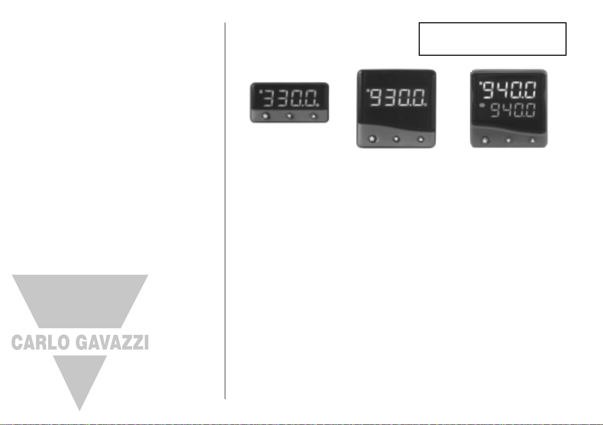
The instruments covered in this manual may be fitted with either a single or a dual
display. Where a single display shows more than one reading, it will alternate
between them.
INITIAL SET-UP
On power-up the controller will display the self test sequence followed by the initial
display inPt : nonE
1 Select input sensor.
Press and hold ✱ and use the ▲ or ▼ buttons to scroll through the sensor selection list
until the correct sensor is displayed. Release the buttons. The display will now read
selected sensor type e.g. inPt : tCs
Press ▲ once The display will now read unit : nonE
2 Select unit.
Press and hold ✱ and use the ▲ or ▼ buttons to scroll through the unit selection list
until the correct unit is displayed. Release the buttons. The display will read selected
unit e.g. unit : °C
Press ▲ once The display will now read SP1.d : nonE
4
English
Page 5
TUNE OR TUNE AT SETPOINT PROGRAM
Enter program (▲▼) and from the display tunE : oFF press and hold ✱ and press ▲ to
display tunE : on or tunE : At.SP Exit program mode (▲▼).
The TUNE program will now start. The display will show tunE as the process temperature
climbs to setpoint.
Note: During tuning, the main setpoint (SP1) LED will flash.
When the TUNE or TUNE AT SETPOINT program is complete the PID values are entered
automatically. The process temperature will rise to setpoint and control should be stable. If
not, this may be because optimum cycle time is not automatically implemented. To set the
cycle time see PROPORTIONAL CYCLE-TIME.
PROPORTIONAL CYCLE-TIME
The choice of cycle-time is influenced by the external switching device or load. eg.
contactor, SSR, valve. A setting that is too long for the process will cause oscillation and a
setting that is too short will cause unnecessary wear to an electro-mechanical switching
device.
Factory set
To use the 20 sec factory set cycle-time no action is needed whether autotune is used or
not.
To Manually Select AUTOTUNE Calculated CYCLE-TIME
When AUTOTUNE is completed, enter program (▲▼) and select CYC.t in Level 1. The
display will read CYC.t : 20 (the factory setting).
To view the new calculated optimum value, press and hold both ✱ and ▼ buttons until
indexing stops. The calculated value will be displayed eg. A16. If acceptable, exit program
(▲▼) to implement this setting.
To Pre-select Automatic Acceptance of AUTOTUNE Calculated CYCLE-TIME
Before AUTOTUNE is initiated select CYC.t in Level1, press and hold both ✱ and ▼ buttons
until indexing stops at A
– –
. Exit program (▲▼) to accept calculated value automatically.
To Manually Pre-select Preferred CYCLE-TIME
Before AUTOTUNE is initiated select CYC.t in Level 1, press and hold both ✱ and ▲ or ▼
buttons until indexing stops at preferred value then exit program (▲▼) to accept.
CYCLE-TIME RECOMMENDATIONS
PROGRAMMER
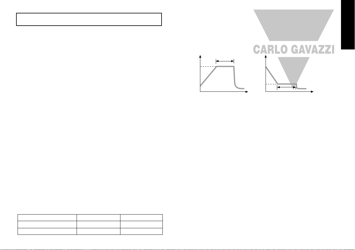
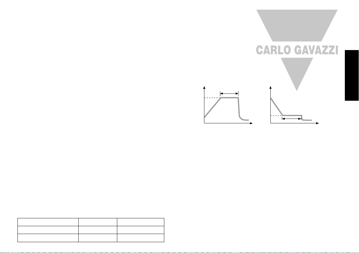
RAMP-SOAK
This feature enables the controller to ramp up or down from current temperature to a
target setpoint at a pre-determined rate. It then controls at the target setpoint for an
adjustable soak period before switching off the SP1 output.
Set Setpoint ramp rate (0 to 9995 deg/hour)
From SPrr in Level 1, press and hold ✱ and ▲ or ▼ to scroll to required ramp rate.
Set Soak (if required) 0 to 1440 minutes
From SoAk
– –
in Level 1, press and hold ✱ and ▲ or ▼ to scroll to required Soak time.
Set Ramp on (Off: On: Hold)
From Sprn in Level 1, press and hold ✱, then press ▲ to select On
Exit program (▲▼) to enter settings into memory and commence ramp to target setpoint.
Notes: In Ramp on configuration, if power is removed from the controller, the Ramp will
re-start when power is restored.
The Ramp hold option suspends the ramp at its last value.
If no Soak period has been set, control at target setpoint continues indefinitely.
SP2 deviation alarms follow the ramp setpoint and can be used to alarm “out of
limits” ramp rate.
WARNING
The Soak timer is triggered when the ramp setpoint reaches the target setpoint. If the
ramp rate is set too fast for the process, the Soak timer will be triggered before the
process temperature reaches the target setpoint.
5
Output Device
Factory Setting
Recommended Minimum
Internal relay: rLY/rLY1/rLY2
20 seconds
20 seconds
10 seconds
Solid state drives: SSd/SSd1/SSd2
0.1 seconds
Target
setpoint
Deg.
Ramp °/hour
Time
Soak
Target
setpoint
Deg.
Ramp °/hour
Time
Soak
Hereafter in the Manual the symbol (▲▼) signifies both buttons are held pressed
for 3 seconds to ENTER or EXIT Program mode.
English
Page 6
SECOND SETPOINT (SP2)
SECOND SETPOINT (SP2) Alarm Output
Configure SP2 output to operate as an alarm from SP2.A in Level 2 and set the
temperature alarm setting in SEt.2 Level 1. The alarm will be triggered when the process
temperature changes according to the options listed below.
dV.hi Rises above the main setpoint by the value inserted at SEt.2.
dV.Lo Falls below the main setpoint by the value inserted at SEt.2.
BAnd Rises above or falls below the main setpoint by the value inserted at SEt.2.
FS.hi Rises above the main setpoint by a SEt.2 value that is greater than the setpoint.
FS.Lo Falls below the main setpoint by a SEt.2 value that is smaller than the setpoint.
SUBSIDIARY SP2 MODE
The following additional alarm functions can be added to the above alarm configurations
using the features found in SP2.b in Level 2.
LtCh Once activated, the alarms will latch and can be manually reset when the alarm
condition has been removed.
Hold This prevents any alarm operation on power-up and is automatically disabled
once the process reaches setpoint in order to allow normal alarm operation.
SECOND SETPOINT (SP2) Proportional control output
Configure in Level 1 using CyC.2 to select proportional cycle time and bnd.2 to adjust
proportioning band. For Heat/Cool operation see Operating Manual.
In on/off mode, bnd.2 adjusts SP2 hysterisis.
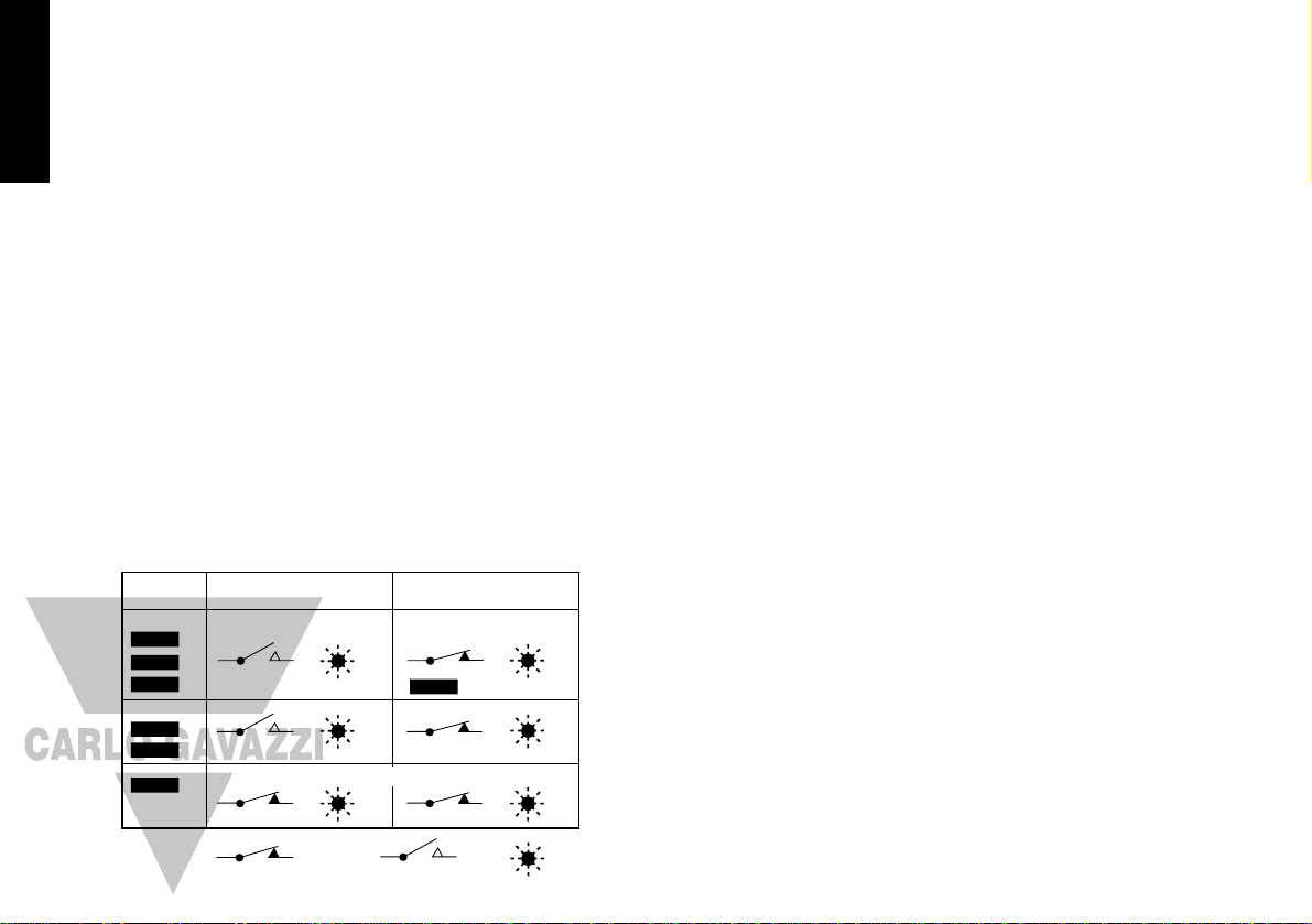
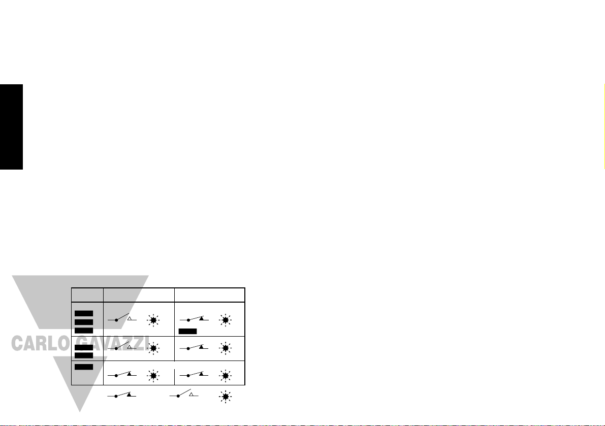
SP2 OUTPUT AND LED INDICATION STATES - IN ALARM CONDITION
SP2 ALARM ANNUNCIATOR
When an SP2 alarm mode is selected in SP2.A the alarm annunciator -AL- is displayed,
alternating with the process temperature, during alarm condition.
Notes: The alarm will be automatically reset when the temperature returns within the
bnd.2 setting in Level 1.
The annunciator may be disabled by selecting function no.AL : on in level 4.
SP2 in cool strategy
See Full Operating Manual (ADVANCED SETTINGS)
ERROR MESSAGES
SENSOR FAULT
Display flashes: inPt: FAiL
Indicates: thermocouple burnout RTD/Pt100 open or short circuit or
negative over-range.
Action: Check sensor/wiring
NON-VOLATILE MEMORY ERROR
Display flashes: dAtA : FAiL
Action: De-power briefly. Replace unit if problem persists
MANUAL POWER ERROR
Display flashes: hAnd : FAiL
SP1 set to ON/OFF in CYC.t
Action: Select proportional mode
IMMEDIATE FAIL ON AUTOTUNE START
Display flashes: tunE : FAiL
Setpoint display 0
1. No setpoint entered.
Action: Enter setpoint
2. SP1 set to ON/OFF in CyC.t
Action: Select proportional mode
Note: To reset and clear error press ▲▼ together briefly to cancel message.
FAIL LATER DURING AUTOTUNE CYCLE
The thermal characteristics of the load exceed the Autotune algorithm limits. The failure
point indicated by any display 0.0 in tech e.g. Ctb = 0.0
Action: 1. Change the conditions. eg. raise setpoint
2. Try tunE : At.SP
3. If the error message persists, call local CARLO GAVAZZI representative for
advice.
Alarm type ON-OFF
operating mode
Proportional
operating mode
F
S
.H
I
C
O
O
L
F
S
.L
O
B
A
N
D
D
V
.L
O
D
V
.H
I
Deviation
Full scale
Strategy
SP2
Output state
SP2
LED state
SP2
Output state
SP2
LED state
B
A
N
D
: on-off mode only
Output ON
(Relay or SSd energised)
Output OFF
(Relay or SSd de-energised)
LED ON
Temperature above setpoint
Legend
English
6
Page 7
FUNCTION LIST (LEVELS 1 TO 4)
Note: A Functions Menu is shown on page 3.
LEVEL 1
Function Options
[Factory settings] shown in brackets
SELECT AUTOTUNE (see pages 4/5)
tunE [oFF] on ParK At.Sp
Used to switch the Autotune feature on and off, to select ParK or Autotune at setpoint.
ParK temporarily turns the output(s) off. To use select ParK and exit program mode. To
disable re-enter program at tunE and select oFF.
SP1 OPERATING PARAMETERS
bAnD 0.1 to * C/°F
[10ºC/18ºF]
SP1 proportional band/Gain or Hysteresis
* 25% sensor maximum Proportional control eliminates the cycling of on-off control. Heater
power is reduced, by time proportioning action, across the proportional band.
int.t oFF 0.1 to 60 minutes
[5.0]
SP1 integral time/reset
Auto-corrects proportional control offset error
dEr.t oFF 1 - 200 seconds
[25]
SP1 derivate time/rate
Suppresses overshoot and speeds response to disturbances
dAC 0.5 - 5.0 x bAnd
[1.5]
SP1 derivative approach control dAC
Tunes warm-up characteristics, independent of normal operating conditions, by controlling
when derivative action starts during warm-up (smaller dAC value = nearer setpoint).
CyC.t A
– –
on.oF 0.1 - 81 sec
[20]
SP1 proportional cycle-time (see pages 9/10)
Determines the cycle rate of the output device for proportional control. Select on.oF for
ON/OFF mode.
oFSt [0] to * °C/°F
SP1 offset/manual reset
* ±50% bAnd. Applicable in proportional and ON/OFF mode with integral disable:
Int.t : oFF.
SP.LK [oFF] on
Lock main setpoint
Locks the setpoint preventing unauthorised adjustment.
PROGRAMMER SETTINGS (see page 5)
Function Options
[Factory settings] shown in brackets
SPrr [0] to 9995 deg/hour
Sets the ramp rate
SPrn on [oFF] hoLd
Switches the ramp on or off, or hold at last ramp value
SoAK
– –
[oFF] 0 to 1440 min
Sets the soak time
SP2 OPERATING PARAMETERS (see page 6)
SEt.2 0 to * °C/°F
[0]
Adjust SP2 setpoint
* Deviation Alarms
DV.hi, DV.Lo, bAnd
25% sensor maximum.
* Full scale alarms
FS.hi, FS.Lo
sensor range f/s
bnd.2 0.1 - * °C/°F
[2.0 °C/3.6°F]
Adjust SP2 hysteresis or proportional band/gain
(see CyC.2 setting)
* 25% sensor f/s
CyC.2 [on.oFF] 0.1–81 seconds
Select SP2 ON/OFF or proportional cycle-time
Select on.oFF for ON/OFF mode, or the cycle rate of SP2 output device for proportional
mode.
LEVEL 2
MANUAL CONTROL MODES
SPI.P 0 to 100 % ‘read only’
Read SP1 output percentage power
hAnd [oFF] 1 to 100 % (not in ON/OFF)
SP1 manual percentage power control
For manual control should a sensor fail. Record typical
SP1.P
values beforehand.
PL.1 100 to 0 % duty cycle
[100]
Set SP1 power limit percentage
Limits maximum SP1 heating power during warm-up and in proportional band.
PL.2 100 to 0 % duty cycle
[100]
Set SP2 percentage power limit (cooling)
7
English
LEVL 1
LEVL 2
Page 8

Dual Relay and Dual SSd output options are factory set.
Note: (when in initial configuration only)Hold ✱ and ▲ or ▼ for 10 seconds to move
to or from output devices in shaded portion.
SP2 OPERATING MODES (see page 6)
Function Options
[Factory settings] shown in brackets
SP2.A [nonE] dV.hi dV.Lo bAnd FS.hi FS.Lo Cool
Main SP2 operating mode
SP2.b [nonE] LtCh hoLd nLin
Subsidiary SP2 mode: latch/sequence
Non-linear cool proportional band
INPUT SELECTION AND RANGING
dI.SP [1] 0.1
Select display resolution: for display of process temperature, setpoint, OFSt, Set.2, hi.SC,
LoSC.
hi.SC sensor minimum [sensor maximum]
°C/°F
Set full scale
Lo.SC [sensor minimum] sensor maximum
°C/ºF
Set scale minimum (default 0°C or 32°F)
inPt Select input sensor [nonE]
(See SENSOR SELECTION table, page 11)
unit [nonE] °C °F bAr Psi Ph rh SEt
Select °C/°F or process units
LEVEL 3
OUTPUT CONFIGURATION
Note: ‘Read only’ after initial configuration. rSET ALL full reset to factory settings required
to change SP1.d subsequently.
SP1.d [nonE] rLY SSd rLY1 rLY2 SSd1
Select SP1 output device
SP2.d [nonE] SSd rLY rLY2 rLY1 SSd2
Read SP2 output device
(read only)
burn Sensor burn-out/break protection
Caution: Settings affect fail safe state.
SP1 SP2
[uP.SC]
Upscale Upscale
dn.SC
Downscale Downscale
1u.2d
Upscale Downscale
1d.2u
Downscale Upscale
rEu.d Select output modes: Direct/Reverse
Caution: Settings affect fail safe state.
SP1 SP2
[1r.2d]
Reverse Direct
1d.2d
Direct Direct
1r.2r
Reverse Reverse
1d.2r
Direct Reverse
Select Reverse on SP1 for heating and Direct for
cooling applications.
rEu.L Select SP1/2 LED indicator modes
SP1 SP2
[1n.2n]
Normal Normal
1i.2n
Invert Normal
1n.2i
Normal Invert
1i.2i
Invert Invert
SPAn [0.0] to ±25% sensor maximum
Sensor span adjust
For recalibrating to align readings with another instrument e.g. External Meter, data logger.
See Full Operating Manual (ADVANCED SETTINGS).
ZEro [0.0] to ±25% sensor f/s
Zero sensor error (see Sensor span adjust above).
ChEK [oFF] on
Select control accuracy monitor
rEAD
[
Var] hi Lo
Read control accuracy monitor
tECh [Ct A] CT b Ct 1 Ct 2 Ct 3 Ct 4 oS 1 uS oS 2
Read Autotune tuning cycle data (see Operating Manual)
UEr Software version number
rSET [nonE] ALL
Resets all functions to factory settings
Caution: This selection will lose all of the current settings.
8
English
LEVL 3
Page 9
LEVEL 4
Access to level 4 is gained through UEr in level 3. Press and hold ▲ and ▼ for 10
seconds.
Enter level 4 at Lock, release ▲ and ▼ together. Display reads LoCK nonE
Program security using Lock
Select from three Lock options: Press and hold ✱, press ▲ to index.
LEV.3 locks level 3 and 4 only- Technical Functions.
LEV.2 locks levels 2, 3 and 4 only - Configuration and
Technical Functions.
ALL locks all functions LoCK ALL
Note: Locked functions and options may be read.
Press ▼ to access following functions
Function Options
[Factory settings] shown in brackets
ProG [Auto] StAY
Program mode auto-exit switch
Auto-exit returns display to normal if 60 seconds of key inactivity, select
StAY
to disable
no.AL [oFF] on
Disable SP2 alarm annunciator -ALSelect on to disable -AL-
di.SS dir 1 to 32 [6]
Display sensitivity
dir = direct display of input 1 = maximum, 32 = minimum sensitivity
dEr.S 0.1 to 1.0 [0.5]
Derivative sensitivity
MECHANICAL INSTALLATION
The Controllers are designed to be mounted either in a 1/16 or a 1/32 DIN panel cutout.
The units are sleeve mounted with the front bezel assembly rated NEMA4/IP66 provided
that:
● the panel is smooth and the panel cutout is accurate;
● the mounting instructions are carefully followed.
DIN PANEL CUTOUT
1/16 DIN: 45.0mm +0.6 / 0.0 wide, 45.0mm +0.6 / 0.0 high
1/32 DIN: 45.0mm +0.6 / -0 wide, 22.2mm +0.3 / -0 high
Maximum panel thickness 9.5mm
Minimum spacing 20mm vertical, 10mm horizontal
MOUNTING
To mount a Controller proceed as follows:
1 Check that the controller is correctly orientated and then slide the unit into the cutout.
2 Slide the panel clamp over the controller sleeve pressing it firmly against the panel until
the controller is held firmly.
3 The controller front bezel and circuit board assembly can be unplugged from the sleeve.
Grasp the bezel firmly by the recesses on each side and pull. A screwdriver can be used
as a lever if required.
4 When refitting the bezel assembly it is important to press it firmly into the sleeve until the
latch clicks in order to compress the gasket and seal to NEMA4X/IP66.
CLEANING
Wipe down with damp cloth (water only)
Note: The controller should be isolated before removing or refitting it in the sleeve, and
electrostatic precautions should be observed when handling the controller outside
the sleeve.
9
DIMENSIONS: MODELS T2032 / T2016
Model Bezel* Behind Panel Overall Behind panel
Width Height Width Height Length Length*
T2032 51.0 28.5 44.8 22.0 116.2 106.7
T2016 51.0 51.0 44.8 44.8 116.2 106.7
Dimensions in mm
* includes gasket
English
LEVL 4
Page 10
ELECTRICAL INSTALLATION
(See important Safety Information page 12)
OUTPUT DEVICES
Two of the following output devices are fitted to the controllers, depending on the model.
1 Solid state relay drive (SSd/SSd1/SSd2)
5Vdc +0/-15%, 15mA non isolating
To switch a remote SSR (or logic)
2 Miniature power relay (rLY/rLY1) 2A/250V AC resistive, Form A/SPST contacts.
3 Sub miniature power relay (rLY2) 1A/250V AC resistive, Form A/SPST contacts.
OUTPUT DEVICE ALLOCATION
Any of the available outputs may be chosen for the main setpoint (SP1), the remaining
device being automatically allocated to the second setpoint (SP2).
Dual relay or dual SSd output models are available to order. Please contact your
local CARLO GAVAZZI distributor for details.
Designed for use with the following supply voltages:
1). 100 - 240V 50-60 Hz 4.5 VA (nominal) +/-10% maximum permitted fluctuation
2). 12V - 24V (AC/DC) +/-20% 4.5 VA Polarity not required
WIRING THE CONNECTOR
Prepare the cable carefully, remove a maximum of 8mm insulation and ideally tin to avoid
bridging. Prevent excessive cable strain. Maximum recommended wire size: 32/0.2mm
1.0mm
2
(18AWG).
INDUCTIVE LOADS
To prolong relay contact life and suppress interference it is recommended engineering
practice to fit a snubber (0.1uf/100 ohms) between terminals 5 and 6.
CAUTION:
Snubber leakage current can cause some electro-mechanical devices to be held
ON. Check with the manufacturers specifications.
EN61010 - /CSA 22.2 No 1010.1 92
Compliance shall not be impaired when fitted to the final installation.
Designed to offer a minimum of Basic Insulation only.
The body responsible for the installation is to ensure that supplementary insulation suitable
for Installation Category II or III is achieved when fully installed.
To avoid possible hazards, accessible conductive parts of the final installation should be
protectively earthed in accordance with EN6010 for Class 1 Equipment.
Output wiring should be within a Protectively Earthed cabinet.
Sensor sheaths should be bonded to protective earth or not be accessible.
Live parts should not be accessible without the use of a tool.
When fitted to the final installation, an IEC/CSA APPROVED disconnecting device should be
used to disconnect both LINE and NEUTRAL conductors simultaneously.
A clear instruction shall be provided not to position the equipment so that it is difficult to
operate the disconnecting device.
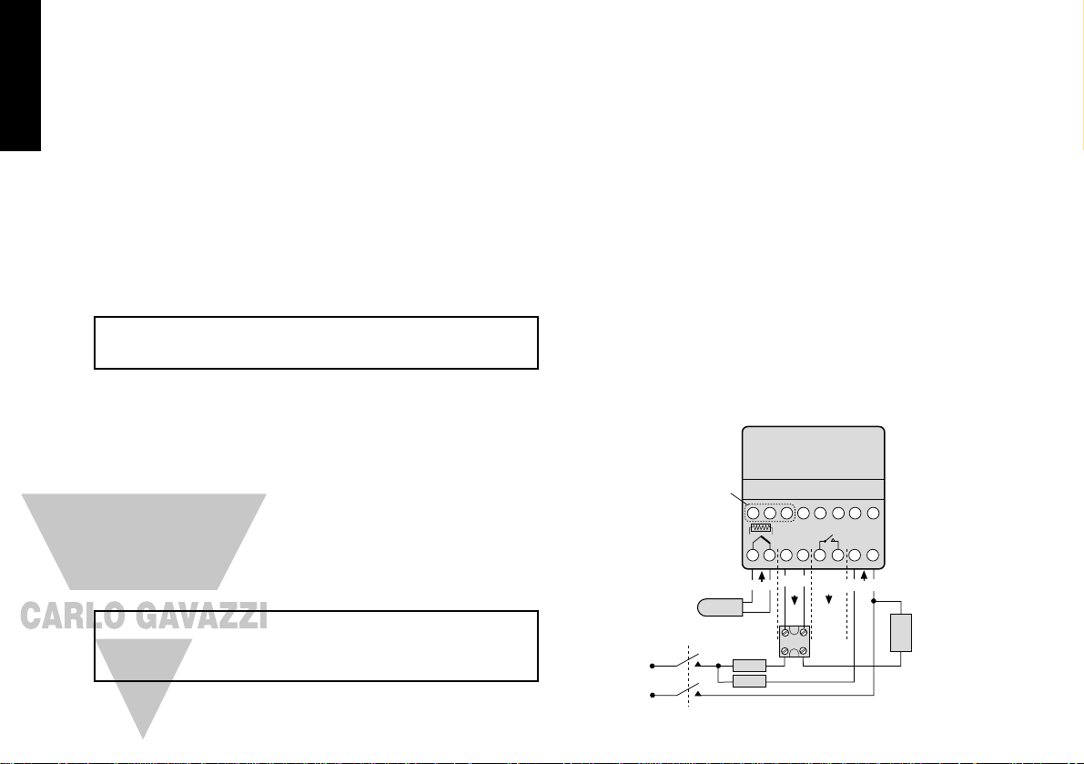
TYPICAL CONNECTION DIAGRAM
In this example the SSR driver output is allocated to SP1 and wired to switch the load
(heater) using an SSR.
F1 Fuse: 1A time lag type to IEC127. CSA/UL rating 250Vac
F2 Fuse: High Rupture Capacity (HRC) Suitable for maximum rated load current
S1 Switch: IEC/CSA/UL Approved disconnecting device
10
Comms option
(when fitted)
1 2 3 4 5 6 7 8
LN
5Vdc
15mA
+
–
+
–
12 13 14 15 16
Sensor
Output
SP1
SP2
Output
SSR
+
–
S1
Sensor
Supply
Line
Open in
alarm
state
9 10 11
Load
F2
F1
Neutral
English
Page 11

SENSOR SELECTION
Thermocouples Description Sensor range Linearity
tC b Pt-30%Rh/Pt-6%Rh 0 to 1800 °C 2.0 *
tC E Chromel/Con 0 to 600 °C 0.5
tC J Iron/Constantan 0 to 800 °C 0.5
tC K Chromel/Alumel -50 to 1200 °C 0.25*
tC L Fe/Konst 0 to 800 °C 0.5
tC n NiCrosil/NiSil -50 to 1200 °C 0.25*
tC r Pt-13%Rh/Pt 0 to 1600 °C 2.0*
tC s Pt-10%Rh/Pt 0 to 1600 °C 2.0*
tC t Copper/Con -200 / 250 °C 0.25*
Resistance
thermometer
rtd Pt100/RTD-2 0.25*
Linear process inputs (Input mV range: 0 to 50mV)
Displays 0 - 20mV 4 - 20mV setpoint limits
Lin1
0 - 100 0 - 400 ± 0.5%
Lin2
0 - 100 -25 - 400 ± 0.5%
Lin3
0 - 1000 0 - 3000 ± 0.5%
Lin4
0 - 1000 -250 - 3000 ± 0.5%
Lin5
0 - 2000 0 - 3000 ± 0.5%
Notes: 1 Linearity: 5-95% sensor range
2 * Linearity B:5° (70º - 500°C) K/N:1° >350°C
exceptions: R/S: 5°<300°C T:1° <- -25° >150°C
RTD/Pt100: 0.5° <-100°C
SPECIFICATION
Thermocouple
9 types
Standards: IPTS/68/DIN 43710
CJC rejection: 20:1 (0.05°/°C) typical
External resistance: 100Ω maximum
Resistance thermometer
RTD-2/Pt100 2 wire
Standards: DIN 43760
(100Ω 0°C/138.5Ω 100°C Pt)
Bulb current: 0.2mA maximum
Linear process inputs
mV range: 0 to 50mV
Applicable to all inputs SM = sensor maximum
Calibration accuracy: ±0.25%SM ±1°C
Sampling frequency: input 10Hz, CJC 2 sec.
Common mode rejection: Negligible effect up to 140dB,
240V, 50-60Hz
Series mode rejection: 60dB, 50-60Hz
Temperature coefficient: 150ppm/°C SM
Reference conditions: 22°C ±2°C, rated voltage after 15
minutes settling time.
Output devices
SSd/SSd1/SSd2: solid state relay driver: To switch a
remote SSR 5Vdc +0/-15% 15mA
non-isolated
Miniature power relay: form A/SPST contacts (AgCdO)
rLY and rLY1: 2A/250ac resistive load
rLY2: 1A/250ac resistive load
General
Displays: Upper, 4 Digits, high brightness
green LED. 10mm (0.4”) high.
Lower, 4 Digits, Orange LED. 9mm
(0.35”) high (T20162 only)
Digital range -199 to 9999
Hi-res mode -199.9 to 999.9
LED output indicators - flashing
SP1 square, green; SP2 round, red
Keypad: 3 elastomeric buttons
Environmental
Humidity: Max 80%
Altitude: up to 2000M
Installation: Categories ll and lll
Pollution: Degree ll
Protection: NEMA 4X, lP66
EMC emission: EN50081-1 FCC Rules 15 subpart J
Class A
EMC immunity: EN50082-2
Ambient: 0-50ºC (32-130°F)
Mouldings: flame retardant polycarbonate
Weight: 130g (4.2 oz)
11
English
Page 12

SAFETY AND WARRANTY INFORMATION
INSTALLATION
Designed for use:
UL873 - only in products where the acceptability is determined by Underwriters
Laboratories Inc.
EN61010-1 / CSA 22.2 No 1010.1 - 92
To offer a minimum of Basic Insulation only.
Suitable for installation within Catagory II and III and Pollution Degree 2.
SEE ELECTRICAL INSTALLATION Page 10
It is the responsibility of the installation engineer to ensure this equipment is installed as
specified in this manual and is in compliance with appropriate wiring regulations.
CONFIGURATION
All functions are front selectable, it is the responsibility of the installing engineer to ensure
that the configuration is safe. Use the program lock to protect critical functions from
tampering.
ULTIMATE SAFETY ALARMS
Do not use SP2 as the sole alarm where personal injury or damage may be caused by
equipment failure.
WARRANTY
CARLO GAVAZZI warrant this product free from defect in workmanship and materials for
three (3) years from date of purchase.
1 Should the unit malfunction, return it to the factory. If defective it will be repaired or
replaced at no charge.
2 There are no user-servisable parts in this unit. This warranty is void if the unit shows
evidence of being tampered with or subjected to excessive heat, moisture, corrosion
or other misuse.
3 Components which wear, or damage with misuse, are excluded e.g. relays.
4 CARLO GAVAZZI shall not be responsible for any damage or losses however caused,
which may be experienced as a result of the installation or use of this product.
CARLO GAVAZZI liability for any breach of this agreement shall not exceed the purchase
price paid E. & O.E.
Copyright CARLO GAVAZZI 2000
Not to be reproduced without prior written permission from CARLO GAVAZZI. Whilst
every effort has been made to ensure the accuracy of the specifications contained in
this manual, due to our policy of continuous development, CARLO GAVAZZI reserves
the right to make changes without prior notice.
12
English
Page 13
Manuel d’Instructions
T2000
Régulateurs de Température
Auto-réglables
Français
CAL Controls
Temperature Controllers
Régulateurs de Température
Page 14

TABLE DES MATIERES CARACTERISTIQUES
DE L’AFFICHEUR
MENU DES FONCTIONS 3
MISE EN SERVICE 4
Mise en service initiale 4
AUTO-REGLAGE 4
Programme d’auto-réglage et d’auto-réglage
au point de consigne 5
TEMPS DE CYCLE PROPORTIONNEL 5
Préconisations concernant le temps de cycle 5
PROGRAMMATEUR 5
Générateur de rampe 5
DEUXIEME POINT DE CONSIGNE (SP2) 6
Messages d’erreur 6
LISTE DE FONCTIONS 7
Niveau 1 7
Niveau 2 7
Niveau 3 8
Niveau 4 9
MONTAGE MECANIQUE 9
Découpe de panneau DIN 9
Montage 9
Nettoyage 9
INSTALLATION ELECTRIQUE 10
Choix du type d’entrée 11
SPECIFICATION 11
SECURITE ET GARANTIE 12
2
Affichage Vert: Température de processus ou en mode configuration: fonction /
option
Affichage Orange: Température de Point de consigne ou en mode configuration: Option
(seulement pour le modèle T20162)
LED Verte: Indicateur de Sortie du Point de Consigne 1
LED Rouge / Orange: Indicateur de Sortie du Point de Consigne 2
REGLAGES
Pour entrer dans ou sortir du mode de configuration: Appuyer simultanément sur les touches ▲ et ▼
pour une durée de 3 secondes
Pour faire défiler les fonctions: Appuyer sur la touche ▲ ou sur la touche ▼
Pour modifier les niveaux ou les options: Appuyer simultanément sur les touches ✱ et ▲, ou
sur les touches ✱ et ▼
Pour visualiser le point de consigne: Appuyer sur la touche ✱
Pour incrémenter le point de consigne: Appuyer simultanément sur les touches ✱ et ▲
Pour décrémenter le point de consigne: Appuyer simultanément sur les touches ✱ et ▼
Pour acquitter une alarme, un message d’erreur: Appuyer simultanément et momentanément sur les
touches ▲ et ▼
Remarques: En cas de difficulté, c’est-à-dire si vous vous perdez dans le mode de configuration, veuillez
appuyer simultanément sur ▲ et sur ▼ pour une durée de 3 secondes, afin de retourner dans le
mode d’affichage, puis lire le paragraphe REGLAGES ci-dessus, et essayer à nouveau.
Dans le mode de configuration, après 60 secondes d’inactivité de touche, l’écran de visualisation
retournera dans inPt : nonE, ou, si la configuration initiale a été terminée, affichera la valeur
mesurée. Tout réglage terminé sera mémorisé par l’appareil.
Cette page peut être photocopiée, puis
utilisée comme une aide visuelle et
comme un signet lors de la lecture des
autres parties de ce manuel.
!
English
Français
Page 15
Cette page peut être photocopiée, puis
utilisée comme une aide visuelle et
comme un signet lors de la lecture des
autres parties de ce manuel.
!
3
MENU DES FONCTIONS
La gamme de réglage est indiqué sous la description
de chaque fonction. Lorsque ceci est approprié, le
réglage d’usine est indiqué en caractères gras.
L’écran de visualisation affiche la lettre K avec le
caractère K
BAND INT.T DER.T DAC CYC.T OFST SP.LK SPRR SPRN SOAK SET.2 BND.2 CYC.2
LEVL 1
TUNE
Auto-réglage ou Park
oFF; on; ParK; At.Sp
Hyst. (Gain) de bande prop. SP1
de 0.1 deg à 25% de la pleine
échelle de sonde (10°C/18°F)
Temps intégrale
Off; de 0.1 à 60 m
inutes
(5 min)
Tem
ps dérivée
O
ff; de 1 à 200 secondes
(25 sec)
Dérivée d’approche
0.5 à 5.0 x bAnd (1.5)
Tem
ps de cycle ou tout ou rien
O
n.off; de 0.1 à 81 sec
(20 sec)
Décalage (Réarm
em
ent m
anuel)
de 0 à 50%
x bAnd
(In.t = off)
Verrouillage de point de
consigne
Off; on
Vitesse de rampe de point de
consigne
de 0 à 9990 degrés/heure
Com
mutation de rampe
Marche/Arrêt
O
n;
off; hold
Durée du palier
O
ff; de 0 à 1440 m
inutes
Réglage de point de
consigne SP2
+/– échelle totale de la sonde
Hyst. (Gain) de bande prop. SP2
de 0,1 deg. à 100%
de la pleine
échelle de sonde (2°C/3.6°F)
Tem
ps de cycle ou tout ou rien
de SP2
O
n.off
; de 0.1 à 81 sec
SP1 SETTINGS
BAUD DATA DBUG
LEVL C
ADDR
Adresse de l’instrum
ent
de 0 à 255
Vitesse de transmission
en bauds 1200: 2400:
4800: 9600: 19k2
Format de données
18n1:18E1:18O
1
Activité de
transmission / réception
Off; on
COMMS SETTINGS
PROGRAMMER SETTINGS SP2 SETTINGS
HAND PL.1 PL.2 SP2.A SP2.B DISP HI.SC LO.SC INPT UNIT
LEVL 2
SP1.P
Lecture de %
de sortie SP1
de 0 à 100%
lecture
seulement
Comm
ande manuelle
de 0 à 100%
Sortie SP1
proportionnel seulem
ent
%
limite de sortie SP1
de 100 à 0%
%
lim
ite de sortie SP2
de 100 à 0%
M
ode SP2 principal
nonE; dV.hi; dV.Lo; bAnd;
FS.hi; FS,Lo; Cool
Deuxième mode SP2
nonE; LtCH; hold; Lt.ho;
nLin
Résolution d’affichage
1 ou 0.1 degré
Réglage m
aximal d’échelle de
0.0 m
ax. à pleine échelle
de sonde
Réglage minimal d’échelle
de 0.0 min. à pleine
échelle de sonde
Sélection du type d’entrée
nonE
Sélection d’unité d’affichage
nonE; °C; °F; bAr;
PSi; Ph; rh; SEt
MANUAL ADJUSTMENTS SP2 MODES RANGING CONFIGURE INPUT
SP2.D BURN REU.D REU.L SPAN ZERO CHEK READ TECH
UER
RSET
LEVL 3
SP1.D
Dispositif de sortie SP1
nonE; rlY; SSd
*
Dispositif de sortie SP2
nonE; SSd; rlY
(lecture seulem
ent)
*
Rupture capteur
uP.SC; dn.SC; 1u.2d; 1d.2u
Inversion des sorties
1r.2d; 1d.2d; 1r.2r; 1d.2r
Inversion des LED d’exploitation
1n.2n; 1i.2n; 1n.2i; 1i.2i
Réglage de gamme de sensibilité
de 0.0 à 25%
de la valeur de
pleine échelle de la sonde
Réglage du zéro
de 0.0 à 25%
de la valeur de pleine
échelle de la sonde
Com
mutation du dispositif de surveillance
Off; on
Lecture du dispositif de surveillance
VAr; hi; lo deg
Lecture d’information de réglage
CtA; Ctb; Ct1; Ct2; Ct3;
Ct4; oS1; uS; oS2
Version du logiciel
Réarm
ement
nonE; ALL
CONFIGURE OUTPUT SAFETY SETTINGS CALIBRATION PERFORMANCE DATA
PROG NO.AL DIS.S DER.S
LEVL 4
LOCK
Verrouillage de sécurité
nonE; LEV 3; LEV 2; ALL
Sortie automatique du mode configuration
Auto; StAY
Dévalidation d’affichage d’alarme -AL-
O
ff
; on
Moyennage d’affichage
dir; 1 to 32 (6)
Sensibilité dérivée
0.1 to 1.0 x dEr.t (0.5)
USER-PROTECTED SETTINGS
POINT D’ENTREE DANS LE PROGRAMME
Le niveau C n’est
visible que si le
contrôleur est muni
de l’option de
communication
➔
POINT D’ENTREE DANS
LE REGLAGE INITIAL
➔
APPUYER SUR LES TOUCHES ▼ OU SUR ▲ POUR VISUALISER LES FONCTIONS
APPUYER SIMULTANEMENT SUR ✱ ET SUR ▼ OU SUR ✱ ET SUR ▲
POUR MODIFIER LES NIVEAUX OU LES OPTIONS
Français
Page 16
4 Pour entrer la configuration initiale en mémoire:
Appuyer simultanément sur les touches ▲ et ▼ pour une durée de 3 secondes. L’écran
de visualisation affichera alors ParK et la variable mesurée (la température) (c’est-à-dire
23°C). ParK sera affichée parce que le point de consigne n’a pas encore été saisi.
Pour lire le point de consigne :
Appuyer sur la touche ✱ et maintenir appuyée. L’écran de visualisation affiche alors unit
(c’est-à-dire°C) et 0.
Pour saisir le point de consigne:
Appuyer sur la touche ✱ et la maintenir appuyée, et utiliser les touches ▲ et ▼ pour
accroître ou décroître la valeur en faisant défiler jusqu’à la valeur prescrite. (La vitesse de
défilement des valeurs accélérera en fonction du temps d’appui sur les touches).
LE REGULATEUR FONCTIONNERA ALORS AVEC LES REGLAGES D’USINE
Remarque: Il est possible qu’il soit nécessaire de REGLER le régulateur afin d’obtenir le
contrôle précis d’une application. Veuillez consulter le paragraphe suivant
concernant l’AUTO-REGLAGE.
AUTO-REGLAGE
L’auto-réglage est une procédure effectuée une seule fois afin d’adapter le régulateur au
processus. Choisir l’auto-réglage ou l’auto-réglage au point de consigne en fonction des
critères ci-dessous.
N’utiliser l’auto-réglage que lorsque la température de charge est égale ou presque égale à
la température ambiante. La procédure appliquera des perturbations lorsque la
température atteint 75% de la valeur du point de consigne, provoquant ainsi un
dépassement qui est alors mesuré afin de permettre le réglage du dispositif contrôle
d’approche (DAC). Prendre toutes les précautions nécessaires afin d’assurer que tout
dépassement possible soit sans danger pour le processus.
L’auto-réglage au point de consigne est conseillé lorsque :
●
Le procédé est déjà au point de consigne, et la régulation n’est pas bonne
●
Le point de consigne est inférieur à 100°C
●
En cas de nouveau réglage à la suite d’une grande modification du point de consigne
●
En cas de régulation multi-zones ou de régulation chaud/froid.
Remarques: Le DAC n’est pas réglé à nouveau par l’auto-réglage au point de consigne.
Il est possible de pré-sélectionner le temps de cycle proportionnel avant de
lancer le programme auto-réglage au point de consigne. (Consulter la page 5).
PROGRAMME D’AUTO-REGLAGE OU D’AUTO-REGLAGE AU POINT DE
CONSIGNE
Entrer dans le programme (▲▼), puis, à partir de l’écran tunE : oFF , appuyer sur la touche
✱ et la retenir appuyée, et utiliser la touche ▲ afin d’afficher tunE : on ou tunE : At.SP.
Sortir du mode de programmation (▲▼).
MISE EN SERVICE
Il est nécessaire de programmer l’information suivante après la mise sous tension du
contrôleur:
Le type de sonde (Se référer à la liste de sondes de température de la page 11)
L’unité de mesure (Se référer à la liste d’unités de la page 8)
L’affectation du dispositif de sortie à SP1 / SP2 (Relais ou SSd)
Le point de consigne de température
Lorsque l’information ci-dessus a été programmée dans le régulateur, celui-ci fonctionnera
alors avec les réglages d’usine suivants :
Gain de bande proportionnelle 10°C / 18°F
Temps d’intégrale 5 minutes
Temps de dérivée 25 secondes
Temps de cycle proportionnel 20 secondes
(Réglage typique du relais de sortie)
Contrôle de dérivée d’ approche 1,5
(Réglage moyen de dépassement minimal)
Les instruments compris dans ce manuel sont munis d’un écran de visualisation
simple ou double. Si un écran de visualisation simple indique plusieurs valeurs,
celles-ci seront affichées d’une façon alternée.
MISE EN SERVICE INITIALE
A la mise sous tension, le régulateur affichera la séquence d’autotest, puis l’écran initial
inPt : nonE
1 Choisir l’entrée capteur
Appuyer sur la touche ✱ et la maintenir appuyée, et utiliser les touches ▲ et ▼ pour
faire défiler la liste de sélection de sonde, jusqu’à ce que la sonde correcte soit affichée
sur l’écran de visualisation. Relâcher les touches. L’écran indiquera le type de sonde
sélectionné, c’est-à-dire inPt : tCs
Appuyer une seule fois sur la touche ▲. L’écran indiquera unit :nonE
2 Sélection de l’unité
Appuyer sur la touche ✱ et la maintenir appuyée, et utiliser les touches ▲ et ▼ pour
faire défiler la liste de sélection d’unité, jusqu’à ce que l’unité correcte soit affichée sur
l’écran de visualisation. Relâcher les touches. L’écran indiquera l’unité sélectionnée,
c’est-à-dire unit : °C
3 Affectation du type de sortie pour la consigne principale SP1
Appuyer une seule fois sur la touche ▲. L’écran indiquera alors SP1.d : nonE
Remarque : Les sorties des modèles comportant des options de sortie à double relais
ou à double unité statique sont pré-configurées. Passer à la Phase 4.
Appuyer sur la touche ✱ et maintenir appuyée, et utiliser les touches ▲ et ▼ pour faire
défiler l’option prescrite : SSd ou rLY . L’écran indiquera le dispositif de sortie
sélectionné, c’est-à-dire SP1.d : SSd
4
A partir d’ici, le symbole (▲▼) utilisé dans ce manuel signifie que l’opérateur
appuie simultanément sur les touches ▲ et ▼ pour une durée de 3 secondes pour
entrer ou sortir du mode de programmation.
Français
Page 17
L’auto-réglage TUNE sera alors lancé. L’écran de visualisation affiche tunE pendant que la
température du processus augmente jusqu’au point de consigne.
Remarque: Pendant le réglage, la LED du point de consigne principal SP1 clignotera.
Lorsque l’auto-réglage ou l’auto-réglage AU POINT DE CONSIGNE est terminé, les valeurs PID
sont automatiquement saisies. La température du processus augmentera jusqu’au point de
consigne, et le contrôle sera stable. Si ceci n’est pas le cas, il est possible que ceci soit dû
au fait que le temps de cycle n’est pas correct. Pour régler le temps de cycle, se référer au
paragraphe TEMPS DE CYCLE PROPORTIONNEL.
TEMPS DE CYCLE PROPORTIONNEL
Le choix du temps de cycle varie en fonction du dispositif de commutation externe ou de
la charge, c’est-à-dire le contacteur, l’unité statique à relais, la valve. Un réglage trop long
pour le processus provoquera l’oscillation, et un réglage trop court provoquera l’usure
inutile d’un dispositif de commutation électromécanique.
Réglage d’usine
Aucune action n’est nécessaire pour utiliser le réglage d’usine de 20 secondes, que le
programme d’auto-réglage soit utilisé ou non.
Pour sélectionner manuellement un TEMPS DE CYCLE calculé par AUTO-REGLAGE:
Lorsque le programme d’AUTO-REGLAGE est terminé, entrer le programme (▲▼) puis
sélectionner CYC.t dans Level 1 [Niveau 1]. L’écran de visualisation affichera CYC.t : 20
(le réglage d’usine).
Pour visualiser la nouvelle valeur optimale calculée, appuyer simultanément sur les touches
✱ et ▼ jusqu’à l’arrêt de l’indexation. La valeur calculée sera alors affichée, c’est-à-dire
A16. Si cette valeur est acceptable, sortir du programme (▲▼) pour saisir ce réglage.
Pour pré-sélectionner l’acceptation automatique d’un TEMPS DE CYCLE calculé par
AUTO-REGLAGE:
Sélectionner CYC.t, dans Level 1 [Niveau 1] avant de lancer le programme d’AUTO-
REGLAGE. Appuyer simultanément sur les touches ✱ et ▼ jusqu’à l’arrêt de l’indexation à
A
– –
. Sortir du programme (▲▼) afin de saisir automatiquement la valeur calculée.
Pour pré-sélectionner manuellement un TEMPS DE CYCLE prescrit:
Sélectionner CYC.t, dans Level 1 [Niveau 1] avant de lancer le programme d’AUTO-
REGLAGE. Appuyer simultanément sur les touches ✱ et ▲, ou sur les touches ✱ et ▼
jusqu’à l’arrêt de l’indexation à la valeur prescrite. Sortir du programme (▲▼) afin de saisir
automatiquement cette valeur prescrite.
PRECONISATIONS CONCERNANT LE TEMPS DE CYCLE
PROGRAMMATEUR
GENERATEUR DE RAMPE
Ce dispositif permet au régulateur d’augmenter ou de diminuer la température, de la
température actuelle à un point de consigne cible, à une vitesse prédéterminée. Lorsque
le point de consigne est atteint, ce dispositif détermine la durée du palier, puis met la
sortie SP1 hors-circuit.
Régler la vitesse de rampe de point de consigne (0 à 9995 degrés / heure) :
Sélectionner SPrr , dans Level 1 [Niveau 1], puis appuyer simultanément sur les touches ✱
et ▲, ou sur les touches ✱ et ▼ pour faire défiler les valeurs de vitesse de rampe jusqu’à la
vitesse de rampe prescrite.
Régler le temps de palier entre 0 et 1440 minutes :
Sélectionner SoAk
– –
dans Level 1 [Niveau 1], puis appuyer simultanément sur les touches
✱ et ▲, ou sur les touches ✱ et ▼ pour faire défiler les temps d’absorption jusqu’au temps
d’absorption prescrit.
Pour valider la RAMPE [Off : Inhibée / On : Validée / Hold : Maintenue]
Sélectionner Sprn, dans Level 1 [Niveau 1], puis appuyer sur la touche ✱ et la maintenir
appuyée, et utiliser la touches ▲ pour sélectionner On [Marche].
Sortir du programme (▲▼) afin de mémoriser automatiquement ces réglages pour
commencer la montée vers le point de consigne cible.
Remarques: Si l’alimentation du régulateur est coupée dans la configuration Ramp on
[Rampe Validée], la Rampe recommencera lorsque l’alimentation sera rétablie.
L’option Ramp hold [Rampe Maintenue] arrête la rampe à sa dernière valeur.
Si aucune durée de palier n’a été réglée, la régulation continue au point de
consigne.
Il est possible d’utiliser les alarmes de déviation SP2, qui suivent la rampe de
point de consigne, pour signaler des vitesses de rampe “hors de limite”.
ATTENTION:
Le début de palier ne commence que lorsque le point de consigne de la rampe atteint le
point de consigne cible. Si la vitesse de rampe réglée est trop élevée pour le processus,
le début de palier sera déclenché avant que la température du processus puisse atteindre
le point de consigne cible.
5
Dispositif de sortie
Réglage d’usine
Durée minimale conseillée
Relais interne : rLY / rLY1 / rLY2
20 secondes
20 secondes
10 secondes
Unités statiques : SSd / SSd1 / SSd2
0.1 secondes
Point de
consigne
cible
Deg.
Rampe en °/heure
Temps
Temps de palier
Deg.
Rampe en °/heure
Temps
Temps de palier
Point de
consigne
cible
Français
Page 18
DEUXIEME POINT DE CONSIGNE (SP2)
Configuration du second point de consigne SP2 en alarme
Configurer la sortie SP2 de façon à ce que celle-ci fonctionne comme une alarme à partir
de SP2.A , dans Level 2 [Niveau 2], puis effectuer le réglage d’alarme de la température
dansSEt.2 , dans Level 1 [Niveau 1]. L’alarme sera déclenchée lorsque la température du
processus change en fonction des options listées ci-dessous :
dV.hi La température du processus dépasse le point de consigne principal par la
valeur saisie dans SEt.2. Alarme suiveuse haute.
dV.Lo La température du processus baisse sous le point de consigne principal par la
valeur saisie dans SEt.2. Alarme suiveuse basse.
BAnd La température du processus dépasse ou baisse sous le point de consigne
principal par la valeur saisie dansSEt.2. Alarme symétrique.
FS.hi La température du processus dépasse le point de consigne principal par une
valeur SEt.2. supérieure à celle du point de consigne. Alarme indépendante
haute.
FS.Lo La température du processus baisse sous le point de consigne principal par une
valeurSEt.2. inférieure à celle du point de consigne. Alarme indépendante
basse.
MODE SP2 AUXILIAIRE
Les fonctions d’alarme suivantes peuvent être ajoutées aux configurations d’alarme
indiquées ci-dessus en utilisant les dispositifs situés dans SP2.b, dans Level 2 [Niveau 2].
LtCh Il est possible d’acquitter manuellement ces alarmes, qui se verrouillent au
déclenchement, lorsque la condition d’alarme a été remédiée.
Hold Ce dispositif, qui inhibe toute opération d’alarme à la mise sous tension, est
automatiquement dévalidé lorsque le processus atteint le point de consigne,
afin de permettre le fonctionnement d’alarme normal.
Configuration du second point de consigne SP2 en régulation
Configurer ceci à partir de CyC.2, dans Level 1 [Niveau 1] afin de sélectionner le temps de
cycle proportionnel, et à partir de bnd.2 pour régler la bande à proportionner. Consulter
le manuel d’instructions pour la régulation chaud/froid.
Le paramètre bnd.2 ajuste l’hystérésis dans le mode on / off [Marche / Arrêt].
ETAT DES SORTIES SP2 ET DES LED D’INDICATION - DANS LA CONDITION D’ALARME
INDICATEUR D’ALARME SP2
Lorsqu’un mode d’alarme SP2 est sélectionné dans SP2A, l’indicateur d’alarme -AL- affiche
d’une façon alternée la température de processus pendant la condition d’alarme.
Remarques: L’alarme sera automatiquement réarmée lorsque la température retourne
dans la gamme du paramètre bnd.2 réglé dans Level 1 [Niveau 1].
Il est possible d’inhiber l’indicateur d’alarme en sélectionnant la fonction
no.AL : on [validé] dans Level 4 [Niveau 4].
SP2 dans la Stratégie de refroidissement
Consulter le paragraphe “configuration en régulation chaud/froid (page 23)”
MESSAGES D’ERREUR
DEFAUT DE SONDE
Message clignotant sur l’écran de visualisation: inPt: FAiL
Ce message indique: thermocouple coupé, RTD/Pt 100 ouvert, court-circuit ou
inversion de polarité.
Action: Vérifier l’état de la sonde / du câblage.
ERREUR DE MEMOIRE NON VOLATILE
Message clignotant sur l’écran de visualisation: dAtA : FAiL
Action: Couper l’alimentation brièvement. Changer le régulateur si
le problème persiste.
ERREUR EN COMMANDE MANUELLE
Message clignotant sur l’écran de visualisation: hAnd : FAiL
Ce message indique: SP1 est réglé sur ON/OFF [tout ou rien] dans CYC.t
Action: Sélectionner le mode proportionnel.
ERREUR IMMEDIATE AU DEMARRAGE DE L’AUTO-REGLAGE
Message clignotant sur l’écran de visualisation: tunE : FAiL
1 Si le point de consigne affiche 0, aucun point de consigne n’a été saisi dans la
mémoire de l’instrument.
Action: 1 Saisir un point de consigne dans la mémoire de l’instrument.
2 Le paramètre SP1 est réglé sur ON/OFF [tout ou rien] dans CyC.t
Action: 2 Sélectionner le mode proportionnel.
Remarque: Pour acquitter ou supprimer l’erreur, appuyer simultanément et
momentanément sur les touches ▲ et ▼ pour annuler le message.
ERREUR PENDANT L’AUTO-REGLAGE
Les caractéristiques thermiques de l’installation dépassent les algorithmes d’auto-réglage.
Ce défaut est signalé par toute valeur 0.0 affichée sur l’écran de visualisation, c’est-à-dire
Ctb = 0.0.
Actions : 1. Modifier les conditions, c’est-à-dire augmenter la valeur du
point de consigne.
2. Essayer tunE : At.SP
3. Si le message d’erreur persiste, demander les conseils du
représentant CARLO GAVAZZI local.
Type d’alarme Mode d’exploitation
TOUT OU RIEN
Mode d’exploitation
proportionnel
F
S
.H
I
C
O
O
L
F
S
.L
O
B
A
N
D
D
V
.L
O
D
V
.H
I
Déviation
Pleine échelle
Stratégie de
refroidissement
Etat de sortie
SP2
Etat de LED
SP2
Etat de sortie
SP2
Etat de LED
SP2
B
A
N
D
: Mode TOUT OU RIEN
seulement
Sortie validée
Relais ou Unité statique
excité(e)
Sortie inhibée
Relais ou Unité statique
désexcité(e)
LED
ALLUMEE
Température dépassant le point de consigne
Légende
Français
6
Page 19
LISTE DES FONCTIONS (NIVEAUX 1 A 4)
Remarque: Un menu des fonctions est fourni à la page 3 de ce manuel.
NIVEAU 1
Fonctions Options
[Réglages d’usine] indiqués entre crochets
SELECTION D’AUTO-REGLAGE (Consulter les pages 4 et 5)
tunE [oFF] on ParK At.Sp
Utilisé pour valider et inhiber le dispositif d’Auto-réglage, pour sélectionner ParK ou Autoréglage au point de consigne.
ParK coupe temporairement la ou les sorties. Pour utiliser ceci, sélectionner ParK puis
sortir du mode de programmation. Pour inhiber ceci, entrer à nouveau dans le programme
à tunE, puis sélectionner oFF.
PARAMETRES D’EXPLOITATION SP1
bAnD 0.1 to * C/°F
[10ºC/18ºF]
Bande proportionnelle de SP1/hystérisis ou gain exprimé en degrés (25% du maximum de
l’étendue capteur).
- La bande proportionnelle permet d’amortir les oscillations.
- l’action proportionnelle à l’intérieur de la bande choisie réduit la puissance de chauffe.
int.t oFF 0.1 to 60 minutes
[5.0]
Temps d’intégral SP1
L’action intégrale corrige automatiquement l’écart mesure/consigne dû à l’action
proportionnelle.
dEr.t oFF 1 - 200 secondes
[25]
Temps dérivé de SP1
L’action dérivée supprime les overshoots et accélère la réponse aux perturbations.
dAC 0.5 - 5.0 x bAnd
[1.5]
Le contrôle d’approche dérivé
Il permet d’améliorer les caractéristiques lors de la montée en température,
indépendamment des conditions normales de fonctionnement. Le réglage détermine le
point de départ de l’action dérivée, par rapport au point de consigne. Une faible valeur de
réglage donne un début d’action proche du point de consigne.
CyC.t A
– –
on.oF 0.1 - 81 secondes
[20]
Temps de cycle proportionnel (Consulter les pages 9 et 10)
Détermine la vitesse de cycle du dispositif de sortie pour le contrôle proportionnel.
Sélectionner on.oF pour le mode ON / OFF (Tout ou rien).
oFSt [0] to * °C/°F
Correction d’écart de statisme de SP1
* ±50 % de bAnd.. Applicable dans le mode proportionnel et dans le mode ON / OFF (Tout
ou rien) avec suppression de l’intégrale: Int.t : oFF.
SP.LK [oFF] on
Verrouillage du point de consigne principal.
Verrouille le point de consigne principal afin d’inhiber tout réglage non autorisé.
REGLAGES DU PROGRAMMATEUR (Consulter la page 5)
Fonctions Options
[Réglages d’usine] indiqués entre crochets
SPrr [0] à 9995 degrés/heure
Détermine la vitesse de rampe.
SPrn on [oFF] hoLd
Pour valider ou inhiber la rampe, ou maintenir à la dernière valeur de rampe.
SoAK
– –
[oFF] de 0 à 1440 minutes
Détermine la durée du palier
PARAMETRES D’EXPLOITATION SP2 (Consulter la page 6)
SEt.2 de 0.1 à * °C/°F
[0]
Ajuste le point de consigne SP2.
* Alarmes de déviation
DV.hi, DV.Lo, bAnd
à 25 % de la valeur maximale du capteur.
* Alarmes de pleine échelle
FS.hi, FS.Lo
de la gamme de pleine échelle du capteur.
bnd.2 de 0.1 à * °C/°F
[2.0 °C/3.6°F]
Règle le gain ou l’hystérésis de bande proportionnelle SP1.
(Consulter le paragraphe concernant le réglage du paramètre CyC.2)
* 25 % de la gamme de pleine échelle du capteur.
CyC.2 [on.oFF] de 0.1 à 81 secondes
Pour sélectionner le mode ON / OFF (Tout ou rien) ou le temps de cycle proportionnel.
Sélectionner on.oFF pour le mode ON / OFF (Tout ou rien), ou le temps de cycle du
dispositif de sortie pour le mode proportionnel.
NIVEAU 2
REGULATION EN MODE MANUEL
SPI.P de 0 à 100 % ‘lecture seulement’
Lecture du pourcentage de puissance de la sortie SP1.
hAnd [oFF] de 1 à 100 % (mais pas dans le mode
ON / OFF (Tout ou rien)
Commande manuelle de la puissance de sortie de SP1.
En cas de rupture capteur, enregistrer les valeurs de
SP1.P
typiques avant la commande en
manuel.
PL.1 de 100 à 0 % du cycle de service
[100]
Limitation de la puissance de sortie de SP1.
Limite la puissance de sortie de SP1, pendant la période de chauffe et dans la bande
proportionnelle.
PL.2 de 100 à 0% du cycle de service
[100]
Limitation de la puissance de sortie SP2.
7
Français
LEVL 1
LEVL 2
Page 20

Les options de sortie à double relais et à double unité statique sont des
réglages d’usine.
Remarque: (Seulement dans le mode de configuration) Appuyer
simultanément sur les touches ✱ et ▲, ou sur les touches ✱ et ▼ pour une
durée de 10 secondes pour accéder à ou sortir des dispositifs de sortie situés
dans la zone ombrée de l’écran de visualisation.
MODE D’EXPLOITATION SP2 (Consulter la page 6)
Fonctions Options
[Réglages d’usine] indiqués entre crochets
SP2.A [nonE] dV.hi dV.Lo bAnd FS.hi FS.Lo Cool
Mode d’exploitation SP2 principal.
SP2.b [nonE] LtCh hoLd nLin
Mode d’exploitation SP2 auxiliaire : mémorisation alarme - inhibition à la première
montée.
Bande proportionnelle froid non linéaire.
CHOIX DE L’ENTREE MESURE ET DE L’ECHELLE
dI.SP [1] 0.1
Choix de la résolution d’affichage pour mesure du point de consigne, des paramètres
OFSt, Set.2, hi.SC, LoSC.
hi.SC température minimale de la sonde [température maximale de la sonde]
°C/°F
Réglage fin échelle
Lo.SC température minimale de la sonde [température maximale de la sonde]
°C/ºF
Réglage début de l’échelle (par défaut 0°C / 32°F)
inPt Choisir entrée capteur [nonE]
(Se référer au tableau de CHOIX DU CAPTEUR de la page 11).
unit [nonE] °C °F bAr Psi Ph rh SEt
Sélectionner°C/°F ou les unités du processus.
NIVEAU 3
CONFIGURATION DES SORTIES
Remarque: ‘En lecture seulement’ après la configuration initiale. Une réinitialisation totale
rSET ALL est prescrite pour toute modification ultérieure de SP1.d .
SP1.d [nonE] rLY SSd rLY1 rLY2 SSd1
Pour choisir le dispositif de sortie SP1.
SP2.d [nonE] SSd rLY rLY2 rLY1 SSd2
Lecture du dispositif de sortie SP2.
(Lecture seulement)
burn Sécurité rupture capteur
Attention: Ces réglages déterminent l’état de sécurité.
SP1 SP2
[uP.SC]
Haut d’échelle Haut d’échelle
dn.SC
Bas d’échelle Bas d’échelle
1u.2d
Haut d’échelle Bas d’échelle
1d.2u
Bas d’échelle Haut d’échelle
rEu.d Choix de la sortie : Directe / Inverse
Attention: Ces réglages déterminent l’état de sécurité.
SP1 SP2
[1r.2d]
Inversé Direct
1d.2d
Direct Direct
1r.2r
Inversé Inversé
1d.2r
Direct Inversé
Pour SP1, sélectionner Reverse (Inverse) pour les régulations “chaud”, et Direct (Direct)
pour les régulations “froid”.
rEu.L Sélection des modes des indicateurs à LED SP1 et SP2
SP1 SP2
[1n.2n]
Normal Normal
1i.2n
Inverse Normal
1n.2i
Normal Inverse
1i.2i
Inverse Inverse
SPAn [0.0] jusqu’à ± 25 % de la valeur maximale du capteur
Réglage du maximum d’échelle.
Pour ré-étalonner afin d’adapter les lectures avec un autre instrument, c’est-à-dire un
instrument de mesure externe, un enregistreur de données.
Consulter le paragraphe REGLAGE.
ZEro [0.0] jusqu’à ± 25 % de la pleine échelle capteur
Rattrapage écart sur le zéro du capteur.
ChEK [oFF] on
Mise en route du moniteur de contrôle.
rEAD
[
Var] hi Lo
Lecture des variables du moniteur de contrôle.
tECh
[
Ct A] CT b Ct 1 Ct 2 Ct 3 Ct 4 oS 1 uS oS 2
Lecture des paramètres de l’auto-réglage
UEr Numéro de version du logiciel
rSET [nonE] ALL
Pour remettre toutes les fonctions au réglage d’usine.
Attention: La sélection de cette option entraînera la perte de tous les réglages actuels
saisis en mémoire.
8
Français
LEVL 3
Page 21

NIVEAU 4
Accéder au niveau 4 par l’intermédiaire de UEr, dans Level 3 (Niveau 3). Appuyer
simultanément sur les touches ▲ et ▼ pour une durée de 10 secondes.
Entrer dans le niveau 4 à Lock, puis relâcher simultanément les touches ▲ et ▼. L’écran
de visualisation affichera alors LoCK nonE.
Programmation de la sécurité en utilisant la fonction Lock (Verrouillage).
Sélectionner l’une des trois options de verrouillage. Appuyer sur la touche ✱ et la
maintenir appuyée, et utiliser la touche ▲ pour indexer.
LEV.3 Pour verrouiller le niveau 3 et le niveau 4 seulement – les
Fonctions Techniques.
LEV.2 Pour verrouiller les niveaux 2, 3 et 4 seulement – les
fonctions de Configuration et les Fonctions Techniques.
ALL Pour verrouiller toutes les fonctions LoCK ALL
Remarque: Il est possible d’effectuer la lecture des fonctions et des options verrouillées.
Utiliser la touche ▼ pour accéder aux fonctions suivantes ;
Fonctions Options
[Réglages d’usine] indiqués entre crochets
ProG [Auto] StAY
Sortie automatique du mode de programmation.
La sortie automatique entraîne un retour à l’affichage normal après 60 secondes de nonutilisation des touches. Choisir
StAY
pour supprimer la sortie automatique.
no.AL [oFF] on
Suppression de l’affichage de l’alarme, choisir on(Marche) pour inhiber -AL-.
di.SS dir 1 to 32 [6]
Sensibilité d’affichage
dir = affichage direct de l’entrée, 1 = sensibilité maximale, 32 = sensibilité minimale.
dEr.S 0.1 to 1.0 [0.5]
Sensibilité de la dérivée.
MONTAGE MECANIQUE
Les régulateurs sont conçus pour le montage dans une découpe de panneau DIN de
1,6mm ou de 0,8mm d’épaisseur. Les régulateurs sont montés à l’aide d’une bague de
montage, et offrent une étanchéité en face avant conforme à la norme
NEMA4 / IP66 si :
● le panneau est lisse, avec une découpe précise;
● les instructions de montage sont suivies avec soin.
DECOUPE DE PANNEAU DIN
Panneau DIN de 1,6 mm d’épaisseur : 45,0mm + 0,6 - 0,0 de largeur, 45,0mm + 0,6 - 0,0
de hauteur.
Panneau DIN de 0,8 mm d’épaisseur : 22.2mm + 0,6 - 0,0 de largeur, 45,0mm + 0,3 - 0,0
de hauteur.
Epaisseur maximale de panneau ; 9,5mm.
Espacement minimal : 20mm d’espacement vertical, 10mm d’espacement horizontal.
MONTAGE
Effectuer le montage du régulateur de la façon suivante:
1 Vérifier l’orientation correcte du régulateur, puis insérer celui-ci dans la découpe du
panneau.
2 Faire coulisser le collier de fixation sur le manchon du régulateur, en appuyant celui-ci
fermement contre le panneau jusqu’à ce que le régulateur soit tenu solidement.
3 Le régulateur peut être débroché de l’avant. Saisir la face avant par les côtés et tirer
pour l’extraire. Au besoin, utiliser un tournevis comme levier, pour faciliter l’extraction.
4 Lors du montage de la face avant, il est important d’enfoncer celle-ci fermement dans le
manchon jusqu’au déclic d’enclenchement du dispositif de verrouillage, afin de
compresser la garniture et le joint d’étanchéité d’une façon conforme à la norme
NEMA4 / IP66.
NETTOYAGE
Nettoyer le régulateur avec un chiffon humide (en utilisant seulement de l’eau).
Remarque: Isoler galvaniquement le régulateur avant de démonter ou de monter à
nouveau celui-ci dans le manchon. Observer des précautions de protection
électrostatique pendant la manipulation du régulateur lorsque celui-ci a été
extrait de son manchon.
DIMENSIONS : MODELES T2032 / T2016
9
Modèle Face avant* Derrière le panneau Longueur Longueur
hors tout derrière le
panneau*
Largeur Hauteur Largeur Hauteur
T2032 51.0 28.5 44.8 22.0 116.2 106.7
T2016 51.0 51.0 44.8 44.8 116.2 106.7
Dimensions en mm.
* y compris le joint d’étanchéité.
Français
LEVL 4
Page 22

INSTALLATION ELECTRIQUE
(Se référer aux Renseignements de Sécurité Importants de la page 12).
TYPES DE SORTIE
Selon le modèle, le régulateur sera muni de deux des dispositifs de sortie suivants ;
1 Sortie logique (SSd / SSd1 / SSd2)
5V CC + 0 – 15% 15MA non isolée
Pour la commutation d’un relais statique (ou logique) éloigné.
2 Relais de puissance miniature (rLY / rLY1) résistif de 2A / 250V CA
A/SPST Relais à simple contact interrupteur.
3 Relais de puissance subminiature (rLY2) résistif de 1A / 250V CA
A/SPST Relais à simple contact interrupteur.
AFFECTATION DES TYPES DE SORTIE
Il est possible de sélectionner n’importe laquelle des sorties disponibles pour le point de
consigne principal. Le second dispositif sera automatiquement assigné au second point de
consigne (SP2).
Les modèles de régulateur à double relais ou à double unité statique sont
disponibles à la commande. Pour obtenir tout renseignement supplémentaire,
veuillez contacter votre distributeur CARLO GAVAZZI local.
Les régulateurs sont conçus pour l’utilisation avec les tensions d’alimentation suivantes:
1). Tensions de 100V à 240V, avec fréquence de 50 à 60Hz, avec consommation de
4,5VA, à fluctuation admissible de ±10%.
2). Tensions de 12V à 24V (CA / CC), ±20%, avec consommation de 4,5VA, polarité non
nécessaire.
CABLAGE DU CONNECTEUR
Préparer le câble avec soin. Dénuder l’extrémité des fils en enlevant l’isolant sur une
longueur maximale de 8mm, et, idéalement, étamer l’extrémité dénudée afin d’éviter les
contacts à court-circuit. Eviter de trop tendre les fils. La taille de fil maximale conseillée est :
32 / 0,2mm, 1,0mm
2
(18 AWG).
CHARGES INDUCTIVES
Dans le but de prolonger la vie des contacts de relais et de supprimer les parasites, la
pratique technique conseille de monter un circuit comportant un condensateur
d’amortissement de 0,1°f / une résistance d’amortissement de 100 ohms entre les bornes 5
et 6 du régulateur.
ATTENTION: Dans le cas d’une charge à très faible consommation, le courant de fuite
du circuit RC s’apparente à un contact fermé (voir spécifications constructeur).
EN61010 - / CSA 22.2 No 1010.1 92
La conformité ne sera pas compromise lors du branchement dans l’installation finale.
Conçu afin de n’offrir qu’un isolement de base minimal.
L’organisation responsable de l’installation devra assurer la réalisation d’un isolement
supplémentaire approprié pour une installation finie de Catégorie II ou de Catégorie III.
Les parties conductrices de l’installation finale doivent être mises à la masse selon la norme
de protection EN6010 pour le Matériel de Classe 1.
Le câblage de sortie doit être confiné dans une armoire munie d’une prise de terre de
protection.
Les protecteurs des sondes doivent être branchés à une prise de terre de protection, ou
être montés dans une position non accessible.
Les parties branchées à la phase doivent être montées de façon à n’être accessibles que
grâce à l’utilisation d’un outil.
Le dispositif sectionneur d’isolement homologué IEC / CSA monté dans l’installation doit
être utilisé de façon à déconnecter simultanément la PHASE et le NEUTRE.
Une instruction explicite de ne pas positionner du matériel de façon à empêcher ou
entraver l’utilisation du dispositif sectionneur d’isolement sera affichée d’une façon claire et
nette près de ce dispositif.
SCHEMA DE BRANCHEMENT TYPIQUE
Dans cet exemple, la sortie logique SSD est affectée à SP1, et câblée à la charge (de
chauffage) en utilisant une unité statique à relais.
Fusible F1 Fusible de type retardé Conforme à la norme IEC 127, à valeur nominale
CSA / UL de 250 VCA.
Fusible F2 Fusible à capacité de rupture élevée HRC approprié pour le courant de
charge nominal maximal.
Commutateur S1 Dispositif sectionneur d’isolement homologué IEC / CSA / UL.
10
Option de
communication
(si montée)
1 2 3 4 5 6 7 8
LN
5Vcc
15mA
+
–
+
–
12 13 14 15 16
Sonde
Sortie
SP1
SP2
Sortie
SSR
+
–
S1
Sonde
Alimentation
Phase
Ouvert
dans
l’état
d’alarme
9 10 11
Charge
F2
F1
Neutre
Unité statique
à relais
Français
Page 23

CHOIX DU CAPTEUR DE TEMPERATURE
Thermocouples Description Gamme de sensibilité Linéarité
de la sonde
tC b Pt-30%Rh/Pt-6%Rh de 0°C à 1800°C 2.0 *
tC E Chromel/Con de 0°C à 600°C 0.5
tC J Fer/Constantan de 0°C à 800°C 0.5
tC K Chromel/Alumel de -50°C à 1200°C 0.25*
tC L Fe/Konst de 0°C à 800°C 0.5
tC n NiCrosil/NiSil de -50°C à 1200°C 0.25*
tC r Pt-13%Rh/Pt de 0°C à 1600°C 2.0*
tC s Pt-10%Rh/Pt de 0°C à 1600°C 2.0*
tC t Cuivre/Con de -200°C / 250°C 0.25*
Sonde à résistance
électrique
rtd Pt100/RTD-2 0.25*
Entrées de processus linéaires (Gamme de sensibilité en mV : de 0 mV à 50 mV)
Affichages de 0 à 20mV de 4 à 20mV Limites de point de consigne
Lin1
de 0 à 100 de 0 à 400 ± 0.5%
Lin2
de 0 à 100 de -25 à 400 ± 0.5%
Lin3
de 0 à 1000 de 0 à 3000 ± 0.5%
Lin4
de 0 à 1000 de -250 à 3000 ± 0.5%
Lin5
de 0 à 2000 de 0 à 3000 ± 0.5%
Remarques: 1 Linéarité: de 5% à 95% de la gamme de sensibilité de la sonde
2 * Linéarité B:5° (de 70°C à 500°C) K/N: 1° >350°C.
Exceptions: R/S: 5°<300°C T:1° <- -25° >150°C
RTD / Pt100: 0,5° <-100°C.
SPECIFICATIONS
Thermocouple
9 types
Standards: IPTS/68/DIN 43710
Atténuation CJC: Atténuation typique de 20:1 (0,05°/°C)
Résistance externe: Résistance Maximale de 100Ω
Thermomètre à résistance électrique
RTD - 2 / Pt 100 à 2 fils
Standards: DIN 43760
100Ω à 0°C / 138,5Ω à 100°C Pt
Courant dans la sonde: Courant maximal de 0,2 mA
Entrées de processus linéaires
Gamme de sensibilité en mV: de 0 mV à 50 mV
Renseignements applicables pour toutes les entrées MS (entrées maximales de sonde)
Précision d’étalonnage: ±0,25 % MS ±1°C
Fréquence d’échantillonnage: Entrée de 10Hz avec CJC de 2 secondes
Atténuation de mode commun: Effet négligeable jusqu’à 140dB, 240V, de 50 à 60Hz
Atténuation de mode série: 60dB, de 50 à 60Hz
Coefficient de température: 150ppm/°C MS
Conditions de référence: 22°C ±2°C, tension nominale après une durée de
repos de 15 minutes
Dispositifs de sortie
SSd / SSd1 / SSd2: sorties logiques pour commuter une unité statique à
relais de 5V CC + 0 – 15% de 15mA, dispositif non isolé
Relais de puissance miniature: avec contacts de forme A / Relais à simple contact
interrupteur (AgcdO)
rLY et rLY1: relais à charge résistive de 2A / 250V CA
rLY2: relais à charge résistive de 1A / 250V CA
Renseignement Généraux
Ecran de visualisation supérieur: à 4 caractères, à LED vertes à haute luminosité de
10mm de hauteur (0,4 pouces anglais)
Ecran de visualisation inférieur : à 4 caractères, à LED
oranges de 9mm de hauteur (0,35 pouces anglais)
(seulement pour le régulateur T20162). Gamme
numérique : de - 199 à 9999. Mode de haute
résolution : de - 199,9 à 999,9
Indicateurs de sortie à LED - LED SP1 verte, carrée et
clignotante, LED SP2 ronde et rouge.
Clavier : 3 boutons en matière élastomère.
Renseignements concernant l’Environnement
Humidité: humidité maximale de 80%
Altitude: jusqu’à 2000 mètres
Installation: de Catégorie II et de Catégorie III
Pollution: Degré II
Protection: NEMA 4X, IP66
Emission de compatibilité
électromagnétique: Conforme à la norme EN50081 - 1, Règles FCC No. 15,
sous-paragraphe J, Classe A.
Immunité de compatibilité
électromagnétique: Conforme à la norme EN50082 - 2
Température ambiante: de 0°C à 50°C (de 32°F à 130°F)
Moulages: en polycarbonate ignifugé
Poids: 130g (4,2 onces)
11
Français
Page 24

RENSEIGNEMENTS CONCERNANT LA
SECURITE ET LA GARANTIE
INSTALLATION
Conçu pour l’utilisation :
UL873 - seulement dans les produits où l’acceptabilité est déterminée par Underwriters
Laboratories Inc.
EN61010 - 1 / CSA 22.2 No. 1010.1 - 92
Conçu afin de n’offrir qu’un isolement de base minimal.
Approprié pour le montage dans les installation de Catégorie II et de Catégorie III, et d’un
degré de Pollution 2.
Consulter le paragraphe INSTALLATION ELECTRIQUE de la page 10.
L’ingénieur effectuant l’installation est responsable d’assurer que le matériel soit installé
selon la méthode indiquée dans ce manuel, et d’une façon conforme aux règlements de
câblage en vigueur.
CONFIGURATION
Toutes les fonctions peuvent être sélectionnées de l’avant du régulateur. L’ingénieur
effectuant l’installation doit s’assurer que la configuration de l’installation ne présente aucun
danger. Utiliser le dispositif de verrouillage de programme afin de protéger les fonctions
critiques contre les modifications non autorisées.
ALARMES DE SECURITE ULTIMES
Ne pas utiliser la fonction SP2 comme le seul moyen d’alarme dans tous les cas où la
blessure des personnes ou les dégâts peuvent être provoqués par la défaillance du
matériel.
GARANTIE
La société CARLO GAVAZZI garantit l’absence de défauts de malfaçon et de matière de ce
produit pour une période de trois (3) ans à partir de la date d’achat de celui-ci.
1 En cas de disfonctionnement, renvoyer l’appareil à l’usine. Si celui-ci s’avère
être défectueux, la réparation ou le remplacement de l’unité sera effectué.
gratuitement.
2 Le régulateur ne comporte aucune pièce réparable par l’utilisateur. La garantie sera
annulée si le régulateur montre des traces de tripatouillage, ou si celui-ci a été soumis
à une chaleur excessive, à une humidité excessive, à la corrosion, à toute utilisation
anormale ou à tout autre abus.
3 Les composants soumis à l’usure ou aux dégâts d’utilisation anormale, tels que les relais,
sont exclus de la garantie.
4 La société CARLO GAVAZZI ne sera pas responsable pour tout dégât ou toute perte
occasionné, quelle qu’en soit la cause, résultant de l’installation, de l’utilisation ou
de l’exploitation de ce produit. La responsabilité de la société CARLO GAVAZZI
concernant toute infraction de cet accord n’excédera pas le prix d’achat E et O.E du
régulateur.
Copyright CARLO GAVAZZI 2000
Ce document ne doit pas être reproduit sans avoir préalablement obtenu
l’autorisation écrite de la société CARLO GAVAZZI. Bien que tout effort soit entrepris
pour assurer la précision des spécifications indiquées dans ce manuel, dû à notre
politique de développement continu, la société CARLO GAVAZZI se réserve le droit
d’effectuer des modifications sans autre préavis.
12
Français
Page 25

Benutzerhandbuch
T2000 Autotune
Temperaturregler
Deutsch
Temperaturregler
Page 26

INHALT MERKMALE DER
INSTRUMENTENTAFEL
FUNKTIONSMENÜ 3
INBETRIEBNAHME 4
Grundeinstellung 4
AUTOTUNE 4
Tune- oder Tune-at-Setpoint-Programm 5
PROPORTIONALE ZYKLUSZEIT 5
Zykluszeit-Empfehlungen 5
PROGRAMMIERER 5
Rampe -Vorwärmung 5
ZWEITER SOLLWERT (SP2) 6
Fehlermeldungen 6
FUNKTIONSLISTE 7
Ebene 1 7
Ebene 2 7
Ebene 3 8
Ebene 4 9
MECHANISCHE INSTALLATION9
DIN-Tafel-Aussparungen 9
Montage 9
Reinigung 9
ELEKTRISCHE INSTALLATION 10
Fühlerauswahl 11
SPEZIFIKATION 11
SICHERHEIT UND GARANTIE 12
2
Grüne Anzeige: Prozeßtemperatur oder Programm-Funktion/Option
Orange Anzeige: Solltemperatur oder Programm-Option (nur T20162)
Grüne LED: Sollwert 1 Ausgangsanzeige
Rote/orange LED: Sollwert 2 Ausgangsanzeige
JUSTIERUNGEN
Um in Programmiermodus zu gelangen oder ihn zu verlassen: ▲ ▼ zusammen drei Sekunden lang drücken
Um Funktionen zu durchlaufen: ▲ oder ▼ drücken
Um auf eine andere Ebene oder Option zu gehen: ✱▲zusammen oder ✱ ▼ zusammen drücken
Um den Sollwert zu betrachten: ✱ drücken
Um den Sollwert zu erhöhen: ✱ ▲ zusammen drücken
Um den Sollwert zu verringern: ✱ ▼ zusammen drücken
Um einen Alarm- oder Fehlerzustand rückzustellen: ▲ ▼ kurz zusammen drücken
Hinweis: Wenn Sie Schwierigkeiten haben, weil Sie sich im Programmiermodus ‘verlaufen’ haben, drücken Sie
▲ und ▼ 3 Sekunden lang gleichzeitig, um zum Anzeigemodus zurückzugelangen; sehen Sie sich
die obigen INSTRUMENTJUSTIERUNGEN an und versuchen Sie es noch einmal.
In Programmiermodus kehrt die Anzeige nach 60 Sekunden Tasteninaktivität entweder zu
inPt : nonE zurück oder, wenn die anfängliche Konfiguration abgeschlossen ist, zum Meßwert. Alle
bereits abgeschlossenen Einstellungen bleiben erhalten.
Diese Seite kann fotokopiert und bei
Arbeiten in anderen Teilen des
Handbuchs als Anschauungsmaterial
oder Lesezeichen verwendet werden.
!
English
Deutsch
Page 27

Diese Seite kann fotokopiert und bei
Arbeiten in anderen Teilen des
Handbuchs als Anschauungsmaterial
oder Lesezeichen verwendet werden.
3
FUNKTIONSMENÜ
Der Justierungsbereich ist unter der Beschreibung
angegeben. Wo zutreffend, sind die werksseitigen
Einstellungen in Fettdruck angegeben.
Hinweis: Der Buchstabe K wird auf der
Instrumentanzeige durch das Schriftzeichen
K dargestellt.
BAND INT.T DER.T DAC CYC.T OFST SP.LK SPRR SPRN SOAK SET.2 BND.2 CYC.2
LEVL 1
TUNE
Autotune oder Park
oFF; on; ParK; At.Sp
SP1 Pro
p
o
rtio
nalb
ereich
(Verstärkung)/H
yst. 0.1 G
rad
b
is
25%
Fühler-Endw
ert (
10°C/18°F)
Integralzeit (Rückstellung)
Off; 0.1 bis 60 m
in (
5 m
in
)
Differentialzeit (Rate)
O
ff; 1 bis 200 Sek. (
25 Sek.)
Differentialannäherung
0.5 bis 5.0 x bAnd (1.5)
Zykluszeit oder an/aus
O
n.off; 0.1 bis 81 Sek.
(20 Sek.)
Versatz (m
anuelle Rückstellung)
0 bis 50%
x bAnd
(In.t = off)
Sollw
ertverriegelung (SP1)
Off; on
Sollw
ertrampenrate
0 bis 9990 Grad/Std.
Ram
pe aus/an
On; off; hold
Vorwärmungszeit
Off; 0 bis 1440 Min.
SP2 Sollwert justieren
+/– Fühlerendwert
oder Endwert
SP2 Proportionalbereich / Verstärkung /
Hyst. 0.1 Grad bis 100%
Fühlerendw
ert
(2°C/3.6°F)
SP2 Zyklus an/aus
On.off; 0.1 bis 81 Sek.
SP1-EINSTELLUNGEN
BAUD DATA DBUG
LEVL C
ADDR
Instrumentadresse
0 bis 255
Baud-Rate
1200: 2400: 4800:
9600: 19k2
Datenformat
18n1:18E1:18O1
Tx/Rx Aktivität
Off; on
COMM-EINSTELLUNGEN
PROGRAMMIEREREINSTELLUNGEN SP2 EINSTELLUNGEN
HAND PL.1 PL.2 SP2.A SP2.B DISP HI.SC LO.SC INPT UNIT
LEVL 2
SP1.P
SP1 Ausgang %
lesen
0 bis 100%
nur lesen
SP1 manuelle Leistungseinstellung %
0 bis 100% nur im
Proportionalmodus
SP1 Ausgang %
begrenzen
100 bis 0%
SP2 Ausgang %
begrenzen
100 bis 0%
SP2 Hauptmodus
nonE; dV.hi; dV.Lo; bAnd;
FS.hi; FS,Lo; Cool
SP2 Zusatzmodus
nonE; LtCH; hold; Lt.ho;
nLin
Anzeigenauflösung
1 oder 0.1 Grad
Bereichsm
axim
um
einstellen
0.0 Fühlermax.
bis Fühlerendwert
Bereichsmaximum einstellen
0.0 Fühlermin.
bis Fühlerendwert
Eingangsfühler w
ählen
nonE
Anzeigeeinheiten
nonE; °C; °F; bAr;
PSi; Ph; rh; SEt
MANUELLE EINSTELLUNGEN SP2-MODI BEREICHSEINSTELLUNG EINGANG KONFIGURIEREN
SP2.D BURN REU.D REU.L SPAN ZERO CHEK READ TECH
UER
RSET
LEVL 3
SP1.D
SP1 Ausgangsvorrichtung
nonE; rlY; SSd
*
SP2 Ausgangsvorrichtung
nonE; SSd*; rlY (nur lesen)*
Funktion bei Sensorbruch
uP.SC; dn.SC; 1u.2d; 1d.2u
Ausgangsfunktion umkehren
1r.2d; 1d.2d; 1r.2r; 1d.2r
LED Status um
kehren
1n.2n; 1i.2n; 1n.2i; 1i.2i
Bereichjustierung
0.0 bis 25%
Fühlerendwert
Nullijustierung
0.0 bis 25%
Fühlerendwert
W
ächter für Regelgenauigkeit einstellen
Off; on
W
ächter ablesen
VAr; hi; lo deg
Tuningdaten lesen
CtA; Ctb; Ct1; Ct2; Ct3;
Ct4; oS1; uS; oS2
Softw
are-Version
Siehe Anzeige
RÜCKSTELLUNG
nonE; ALL
AUSGANG KONFIGURIERE N SICHERHEITSEINSTELLUNGEN KALIBRIERUNG LEISTUNGSDATEN
PROG NO.AL DIS.S DER.S
LEVL 4
LOCK
Sicherheitsverriegelung
nonE; LEV 3; LEV 2; ALL
Automatisches Verlassen des
Programm
s sperren
Auto; StAY
-AL- Alarmanzeige sperren
Off; on
Anzeigeempfindlichkeit
dir; 1 to 32 (6)
Abw
eichungsem
pfindlichkeit
0.1 to 1.0 x dEr.t (0.5)
VOM BENUTZER GESICHERTE EINSTELLUNGEN
PROGRAMMIEREINGANG
Ebene C nur
sichtbar, wenn
COMMS-Option
installiert ist
➔
EINGANG-GRUNDEINSTELLUNG
➔
▼ ▲ DRÜCKEN, UM FUNKTIONEN ZU BETRACHTEN
✱ ▼ ODER ✱ ▲ ZUSAMMEN BETÄTIGEN, UM VON EINER EBENE
ODER OPTION ZUR ANDEREN ZU GEHEN
!
Deutsch
Page 28

4 Um die Grundeinstellungen in den Reglerspeicher einzugeben
Die ▲ und ▼ Knöpfe beide 3 Sekunden lang drücken und eingedrückt halten. Die
Anzeige zeigt nun abwechselnd ParK und die gemessene Variable (Temperatur)
(z.B. 23). ParK erscheint, weil noch kein Sollwert eingegeben worden ist.
Um den Sollwert zu zeigen
✱ drücken und eingedrückt halten. Auf der Anzeige erscheint nun unit (z.B.°C ) und 0
Um den Sollwert einzugeben
✱ drücken und eingedrückt halten und den ▲ Knopf benutzen, um den Wert zu
erhöhen, oder den ▼ Knopf, um ihn zu vermindern, und auf den geforderten Sollwert
laufen lassen. (Die Zahlenlaufrate erhöht sich mit der Zeit.)
DER REGLER IST NUN FÜR DEN BETRIEB
MIT WERKSEINSTELLUNGEN BEREIT.
Hinweis: Für genaue Regelung einer Anwendung, kann TUNING des Reglers erforderlich
sein. Lesen Sie bitte den folgenden Abschnitt über AUTOTUNE.
AUTOTUNE
Dies ist ein einmaliges Verfahren, mit dem der Regler auf den Prozeß eingestellt wird. Nach
den unten aufgeführten Kriterien entweder Tune oder Tune at Setpoint (Tuning bei
Sollwert) wählen.
Das Tun e-Programm sollte bei kühler Last (Temperatur bei oder nahe der
Umgebungstemperatur) begonnen werden. Der Ausgang wird zyklusmäßig auf 75% des
Sollwertes gebracht, um möglichst jegliche Überschreitung des tatächlichen Sollwertes
während des Tuning-Vorganges zu vermeiden. Die Aufheizungskennlinien werden
überwacht und die DAC-Function (welche zukünftig Sollwertüberschreitungen minimiert)
wird eingestellt. Es ist sicherzustellen, daß eine Überschreitung des Sollwertes während
des Tunings die Produktion nicht gefährdet.
Das Tune at Setpoint-Programm wird empfohlen, wenn
●
der Prozeß den Sollwert bereits erreicht hat, und die Regelung nicht gut ist.
●
der Sollwert unter 100°C liegt.
●
erneutes Tuning nach einer großen Sollwertänderung erforderlich ist.
●
Tuning bei Mehrzonen- und/oder Heiz-/Kühlanwendungen ausgeführt wird.
Hinweise: DAC wird durch Tune at Setpoint nicht nachjustiert.
Vor der Ausführung des Autotune-Programms kann Proportionale Zykluszeit
vorgewählt werden (siehe S. 5).
TUNE- ODER TUNE-AT-SETPOINT-PROGRAMM
In das Programm gehen (▲▼) und von der AnzeigetunE : oFF aus ✱ drücken und
eingedrückt halten und ▲ drücken, damit tunE : on oder tunE : At.SP erscheint.
Programmiermodus verlassen (▲▼).
INBETRIEBNAHME
Nach dem Anschalten muß die folgende Information in den Regler einprogrammiert
werden:
Fühlertyp (Siehe Liste der Temperaturfühler Seite 11)
Anzeigeeinheit (Siehe Liste der Einheiten Seite 8)
Zuordnung der Ausgangsvorrichtung an SP1/SP2 (Relais oder SSd)
Temperatursollwert
Wenn die obige Information im Regler einprogrammiert worden ist, ist dieser mit den
folgenden Werkseinstellungen betriebsbereit:
Proportionalbereich/Verstärkung 10°C/18°F
Integralzeit/Rückstellung 5 Minuten
Differentialzeit/Rate 25 Sek.
Proportionalzykluszeit 20 Sek.
(Typische Einstellung für Relaisausgang)
DAC Differentialannäherungssteuerung 1,5
(durchschnittliche Einstellung für minimales Überschwingen)
Die in diesem Handbuch beschriebenen Instrumente können mit einfacher oder
doppelter Anzeige ausgestattet sein. Wenn eine einfache Anzeige mehr als einen
Meßwert angibt, zeigt die Anzeige diese Meßwerte abwechselnd.
GRUNDEINSTELLUNG
Nach dem Einschalten zeigt der Regler die Selbstprüfungsfolge, gefolgt von der
Anfangsanzeige inPt : nonE
1 Eingangsfühler wählen
✱ drücken und eingedrückt halten und die ▲ und ▼ Knöpfe benutzen, um die
Fühlerwahlliste zu durchlaufen, bis der richtige Fühler erscheint. Die Knöpfe loslassen.
Die Anzeige zeigt nun den gewählten Fühlertyp, z.B inPt : tCs
▲ einmal drücken. Auf der Anzeige erscheint nun unit : nonE
2 Einheit wählen
✱ drücken und eingedrückt halten und die ▲ und ▼ Knöpfe benutzen, um die
Einheitwahlliste zu durchlaufen, bis die richtige Einheit erscheint. Die Knöpfe loslassen.
Die Anzeige zeigt nun die gewählte Einheit, z.B. unit : °C
▲ einmal drücken. Die Anzeige zeigt nun SP1.d : nonE
3 SP1 wählen (Hauptsollwert-Ausgangsvorrichtung)
Hinweis: Bei Modellen mit Doppelrelais- und Doppel-SSd-Ausgabe-Optionen sind
die Ausgänge fertig konfiguriert. Auf Schritt 4 vorgehen.
✱ drücken und eingedrückt halten und die ▲ und ▼ Knöpfe benutzen, um nach
Bedarf SSd oder rLY zu wählen. Die Anzeige zeigt nun die gewählte
Ausgangsvorrichtung, z.B. SP1.d : SSd
4
Im folgenden Text dieses Handbuchs bedeutet das Symbol (▲▼), daß beide Tasten 3
Sekunden lang eingedrückt gehalten werden, um in den Programmiermodus zu
gelangen oder ihn zu verlassen
Deutsch
Page 29

Nun beginnt das TUNE-Programm. Auf der Anzeige erscheint abwechselnd tunE , und die
gemessene Variable, während die Prozeßtemperatur auf den Sollwert ansteigt.
Hinweis: Während des Tuning blinkt die LED-Anzeige für Hauptsollwert (SP1).
Wenn das TUNE- bzw. TUNE AT SETPOINT-Programm abgeschlossen ist, werden die PID-
Werte automatisch eingegeben. Die Prozeßtemperatur steigt auf den Sollwert an, und die
Regelung müßte stabil sein. Wenn dies nicht der Fall ist, kann es daran liegen, daß die
optimale Zykluszeit nicht automatisch implementiert worden ist. Um die Zykluszeit
einzustellen, siehe PROPORTIONALE ZYKLUSZEIT.
PROPORTIONALE ZYKLUSZEIT
Die Wahl der Zykluszeit wird durch die externe Schaltmimik oder durch die Last beeinflußt,
z.B. Schütz, SSR, Ventil. Eine Einstellung, die zu lang für den Prozeß ist, führt zu Oszillation,
und eine Einstellung die zu kurz für den Prozeß ist, verursacht unnötigen Verschleiß einer
elektromechanischen Schaltvorrichtung.
Werkseinstellung
Um die werksseitig eingestellte Zykluszeit von 20 Sekunden zu benutzen, sind keine
Maßnahmen erforderlich, egal ob Autotune benutzt wird oder nicht.
Manuelle Wahl der von Autotune berechneten Zykluszeit
Nachdem AUTOTUNE abgeschlossen ist, gehen Sie in das Programm (▲▼) und wählen
CYC.t in Ebene 1. Auf der Anzeige erscheint nun CYC.t : 20 (Werkseinstellung).
Um den neu errechneten optimalen Wert zu betrachten, werden die Tasten ✱und ▼
beide gedrückt und eingedrückt gehalten, bis die Weiterschaltung aufhört. Nun erscheint
der errechnete Wert, z.B. A16. Wenn dieser akzeptabel ist, verlassen Sie nun das Programm
(▲▼), um diese Einstellung zu implementieren.
Automatische Akzeptierung der von AUTOTUNE errechneten ZYKLUSZEIT im voraus
wählen
Bevor AUTOTUNE ausgelöst wird, CYC.t auf Ebene 1 wählen; die ✱ und die ▼ Taste beide
drücken und eingedrückt halten, bis die Weiterschaltung bei A
– –
aufhört. Das Programm
verlassen (▲▼), um den errechneten Wert automatisch zu akzeptieren.
Bevorzugte ZYKLUSZEIT manuell im voraus wählen
Bevor AUTOTUNE ausgelöst wird, CYC.t auf Ebene 1 wählen; die ✱ und ▲ oder ▼ Tasten
beide drücken und eingedrückt halten, bis die Weiterschaltung bei dem bevorzugten Wert
aufhört, dann das Programm verlassen (▲▼), um diesen zu akzeptieren.
EMPFOHLENE ZYKLUSZEITEN
PROGRAMMIERER
Rampe - Vorwärmung
Diese Funktion ermöglicht es dem Regler, mit einer voreingestellten Rampenfunktion von
der gegenwärtigen Temperatur auf einen Zielsollwert herauf- oder herunterzugehen. Dann
regelt er für eine justierbare Vorwärmzeit am Zielsollwert, bevor er den SP1 Ausgang
ausschaltet.
Sollwert-Rampenrate einstellen (0 bis 9995 Grad/Stunde)
Von SPrr auf Ebene 1 aus ✱ und dann ▲ oder ▼ eindrücken und eingedrückt halten, um
zum geforderten Rampenwert zu gelangen.
Vorwärmung (falls gewünscht) zwischen 0 und 1440 Minuten einstellen.
Von SoAk
– –
auf Ebene 1 aus ✱ drücken und eingedrückt halten, und ▲ oder ▼
drücken, um auf die gewünschte Vorwärmzeit zu gelangen.
Rampe an einstellen (Aus : An : Halten)
Von Sprn auf Ebene 1 aus ✱ drücken und eingedrückt halten, dann ▲ drücken, um On zu
wählen.
Programmieren verlassen (▲▼), um die Einstellungen in den Speicher einzugeben und mit
der Ansteuerung des Zielsollwerts nach der Rampenfunktion zu beginnen.
Hinweise: In der Rampe-an-Konfiguration wird die Rampe, wenn die Stromversorgung des
Reglers unterbrochen wird, neu starten, wenn die Stromversorgung
wiederhergestellt wird.
Die Rampe-halten-Option hält die Rampe auf ihrem letzten Wert.
Wenn keine Vorwärmung-Zeit eingegeben worden ist, wird die Regelung auf
den Sollwert auf unbegrenzte Zeit fortgesetzt.
SP2 Abweichungsalarme folgen dem Rampensollwert und können benutzt
werden, um einen Alarm bei Rampenraten “außerhalb der Grenzen”
auszulösen.
WARNUNG
Der Vorwärmung-Zeitschalter wird ausgelöst, wenn der Rampensollwert den Zielsollwert
erreicht. Wenn die Rampenrate zu schnell für den Prozeß eingestellt ist, wird der
Vorwärmung-Zeitschalter ausgelöst, bevor die Prozeßtemperatur den Zielsollwert
erreicht.
5
Ausgangsvorrichtung
Werkseinstellung
Empfohlener Mindestwert
Internes relais: rLY/rLY1/rLY2
20 Sekunden
20 Sekunden
10 Sekunden
Festkörperantriebe: SSd/SSd1/SSd2
0.1 Sekunden
Ziel-
sollwert
Grad
Rampe °/Stunde
Zeit
Vorwärmen
Ziel-
sollwert
Grad
Rampe °/Stunde
Zeit
Vorwärmen
Deutsch
Page 30

ZWEITER SOLLWERT (SP2)
Zweiter Sollwert (SP2) Alarmausgang
Den SP2 Ausgang von SP2.A auf Ebene 2 als Alarm konfigurieren und die
Temperaturalarmeinstellung in SEt.2 auf Ebene 1 einstellen. Der Alarm wird dann gemäß
den unten aufgeführten Optionen ausgelöst, wenn sich die Prozeßtemperatur ändert.
dV.hi überschreitet den Hauptsollwert um den in SEt.2 eingegebenen Wert.
dV.Lo unterschreitet den Hauptsollwert um den in SEt.2 eingegebenen Wert.
BAnd über- oder unterschreitet den Hauptsollwert um den in SEt.2 eingegebenen Wert.
FS.hi überschreitet den Hauptsollwert um einen SEt.2 Wert, der größer ist als der Sollwert.
FS.Lo unterschreitet den Hauptsollwert um einen SEt.2 Wert, der größer ist als der Sollwert.
SP2 HILFSMODUS
Den obigen Alarmkonfigurationen können die folgenden zusätzlichen Alarmfunktionen mit
Hilfe der in SP2.b in Ebene 2 gebotenen Funktionen hinzugefügt werden.
LtCh Wenn die Alarme aktiviert worden sind, werden sie verriegelt und können
manuell rückgestellt werden, wenn der Alarmzustand gelöscht worden ist.
Hold Dies verhindert Alarmauslösung beim Einschalten und wird, sobald der Prozeß
den Sollwert erreicht, automatisch gesperrt, um normale Alarmfunktion zu
ermöglichen.
ZWEITER SOLLWERT (SP2) Proportionalsteuerungsausgang
Auf Ebene 1 konfigurieren, wobei CyC.2 benutzt wird, um die Proportionalzykluszeit zu
wählen, und bnd.2, um den Proportionalbereich einzustellen. Für Heiz-/Kühlbetrieb siehe
Betriebshandbuch.
In An-Aus-Modus justiert bnd.2 die SP2 Hysterese.
SP2 AUSGANG UND LED-ANZEIGEZUSTÄNDE - IM ALARMZUSTAND
SP2 ALARMMELDER
Wenn ein SP2 Alarmmodus in SP2.A gewählt wird, wird während des Alarmzustands der
Alarmmelder -AL- abwechselnd mit der Prozeßtemperatur gezeigt.
Hinweise: Der Alarm wird automatisch rückgestellt, wenn die Temperatur auf einen Wert
innerhalb der bnd.2 Einstellung auf Ebene 1 zurückkehrt.
Der Melder kann gesperrt werden, indem man Funktion no.AL : on auf
Ebene 4 gewählt.
SP2 in Kühlstrategie
See Full Operating Manual (ADVANCED SETTINGS).
FEHLERMELDUNGEN
FÜHLERFEHLER
Anzeige blinkt: inPt: FAiL
Bedeutet: Thermoelement ausgebrannt RTD/Pt100 offen oder kurzgeschlossen oder
negative Überschreitung.
Maßnahme: Fühler/Verdrahtung kontrollieren.
PERMANENTSPEICHER-FEHLER
Anzeige blinkt: dAtA : FAiL
Maßnahme: Stromversorgung kurz ausschalten. Einheit ersetzen, wenn dies den Fehler
nicht behebt.
MANUELL-STROMVERSORGUNG-FEHLER
Anzeige blinkt: hAnd : FAiL
SP1 auf AN/AUS in CYC.t gestellt.
Maßnahme: Proportionalmodus wählen.
VERSAGEN SOFORT NACH AUTOTUNE-START
Anzeige blinkt: tunE : FAiL
Sollwertanzeige 0.
1. Kein Sollwert eingegeben.
Maßnahme: Sollwert eingeben
2. SP1 auf AN/AUS in CyC.t gestellt.
Maßnahme: Proportionalmodus wählen.
Hinweis: Um den Fehler rückzustellen und zu löschen, werden ▲▼ kurz zusammen
gedrückt, um die Meldung zu löschen.
VERSAGEN SPÄTER WÄHREND DES AUTOTUNE-ZYKLUS
Die Temperaturkennlinien der Last überschreiten die Grenzwerte des AutotuneAlgorithmus. Der Versagenspunkt wird von der jeweiligen Anzeige 0.0 in tech angezeigt,
z.B. Ctb = 0.0
Maßnahme: 1. Bedingungen ändern; z.B. den Sollwert erhöhen.
2. TunE : At.SP ausprobieren.
3. Wenn die Fehlermeldung immer noch erscheint, lassen Sie sich von Ihrer
regionalen CARLO GAVAZZI-Vertretung beraten.
Alarmtyp AN-AUS
Betriebsmodus
Proportional-
betriebsmodus
F
S
.H
I
C
O
O
L
F
S
.L
O
B
A
N
D
D
V
.L
O
D
V
.H
I
Abweichung
Endwert
Strategie
SP2
Ausgangszustand
SP2
LED-Zustand
SP2
Ausgangszustand
SP2
LED-Zustand
B
A
N
D
: nur an-aus-Modus
Ausgang AN
(Relais oder SSd stromführend
Ausgang AUS
(Relais oder SSd stromlos)
LED AN
Temperatur oberhalb des Sollwerts
Legende
Deutsch
6
Page 31

FUNKTIONSLISTE (EBENE 1 bis 4)
Hinweis: Ein Funktionsmenü finden Sie auf Seite 3.
EBENE 1
Funktion Optionen
[Werkseinstellungen] erscheinen in Klammern
AUTOTUNE WÄHLEN (siehe Seiten 4/5)
tunE [oFF] on ParK At.Sp
Wird benutzt, um die Autotune-Funktion an- oder auszuschalten, um ParK oder Autotune
at setpoint (Autotune am Sollwert) zu wählen.
ParK stellt den Ausgang bzw. die Ausgänge vorübergehend aus. Um es zu benutzen, wählt
man ParK und verläßt dann den Programmiermodus. Um es zu sperren, geht man über
tunE wieder in den Programmiermodus und wählt oFF.
SP1 BETRIEBSPARAMETER
bAnD 0.1 bis * C/°F
[10ºC/18ºF]
SP1 Proportionalbereich/Verstärkung oder Hysterese
* 25% Fühler-Maximum. Proportionalregelung verhindert zyklusmäßiges Ein-Aus-Schalten der
Regelung. Die Heizungsleistung wird durch Zeitproportionierungsaktion über den
Proportionalbereich hinweg reduziert.
int.t oFF 0.1 bis 60 minuten
[5.0]
SP1 Integralzeit/Rückstellung
Korrigiert automatisch den Versatzfehler der Proportionalregelung.
dEr.t oFF 1 - 200 Sekunden
[25]
SP1 Differentialzeit/Rate
Unterdrückt Sollwertüberschreitungen und beschleunigt Reaktion auf Störungen.
dAC 0.5 - 5.0 x bAnd
[1.5]
SP1 Differentialannäherungssteuerung dAC
Stellt die Vorwärmungskennlinien unabhängig von den normalen Betriebsbedingungen ein,
indem es regelt, wann die Differentialaktion während der Vorwärmung beginnt (niedrigerer
dAC-Wert = näher zum Sollwert).
CyC.t A
– –
on.oF 0.1 - 81 Sekunden
[20]
SP1 Proportionalzykluszeit (siehe Seiten 9/10)
Bestimmt die Zyklusrate der Ausgangsvorrichtung für Proportionalsteuerung. on.oF für
AN/AUS Modus wählen.
oFSt [0] to * °C/°F
SP1 Versatz/manuelle Rückstellung
*± 50% bAnd.. In Proportional- und An/Aus-Modus mit Integralsperrung anwendbar: Int.t :
oFF.
SP.LK [oFF] on
Hauptsollwert verriegeln
Verriegelt den Sollwert und verhindert unbefugte Justierung.
PROGRAMMIERER-EINSTELLUNGEN (siehe Seite 5)
Funktion Optionen
[Werkseinstellungen] erscheinen in Klammern
SPrr [0] bis 9995 Grad/Stunde
Stellt die Rampenrate ein.
SPrn on [oFF] hoLd
Schaltet Rampe ein oder aus, oder hält am letzten Rampenwert.
SoAK
– –
[oFF] 0 bis 1440 Min.
Stellt die Vorwärmzeit ein.
SP2 BETRIEBSPARAMETER (siehe Seite 6)
SEt.2 0 bis * °C/°F
[0]
SP2 Sollwert justieren
* Abweichungsalarme
DV.hi, DV.Lo, bAnd
25% Fühlermaximum.
* Endwertalarme
FS.hi, FS.Lo
Fühlerbereich-Endwert.
bnd.2 0.1 - bis* °C/°F
[2.0 °C/3.6°F]
SP2 Hysterese oder Proportionalbereich/Verstärkung justieren
(siehe CyC.2 Einstellung)
* 25% Fühler-Endwert
CyC.2 [on.oFF] 0.1–81 Sekunden
SP2 AN/AUS- oder Proportionalzykluszeit wählen
on.oFF oder ON/OFF-Modus wählen, oder die Zyklusrate der SP2 Ausgangsvorrichtung für
Proportionalmodus.
EBENE 2
MANUELLE REGELMODI
SPI.P 0 bis 100% ‘nur lesen’
SP1 Ausgangsprozentleistung lesen
hAnd [oFF] 1 bis 100 % (nicht in AN/AUS)
SP1 manuelle Prozentleistungsregelung
Für manuelle Regelung im Falle von Fühlerversagen.Typische
SP1.P
Werte im voraus
notieren.
PL.1 100 bis 0% Arbeitszyklus
[100]
SP1 Leistungsgrenzenprozentsatz einstellen
Begrenzt die maximale SP1 Heizleistung während des Warmlaufens und im
Proportionalbereich.
PL.2 100 bis 0% Arbeitszyklus
[100]
SP2 Leistungsgrenzenprozentsatz (Kühlung) einstellen
7
Deutsch
LEVL 1
LEVL 2
Page 32

Doppelrelais und Doppel-SSd Ausgangsoptionen sind werksseitig eingestellt.
Hinweis: (nur bei der anfänglichen Konfiguration) ✱ und ▲ oder ▼ 10
Sekunden lang eingedrückt halten, um auf die Ausgangsvorrichtungen im
schattierten Teil zu gehen oder diese zu verlassen.
SP2 BETRIEBSMODI (siehe Seite 6)
Funktion Optionen
[Werkseinstellungen] erscheinen in Klammern
SP2.A [nonE] dV.hi dV.Lo bAnd FS.hi FS.Lo Cool
SP2 Hauptbetriebsmodus
SP2.b [nonE] LtCh hoLd nLin
SP2 Hilfsmodus: Verriegelung/Folge
Nicht-linearer Kühlproportionalbereich
EINGANGSWAHL UND BEREICHSEINSTELLUNG
dI.SP [1] 0.1
Anzeigenauflösung wählen: für Anzeige von Prozeßtemperatur, Sollwert, OFSt, Set.2,
hi.SC, LoSC.
hi.SC Fühlerminimum [Fühlermaximum]
°C/°F
Endwert einstellen
Lo.SC [Fühlerminimum] Fühlermaximum
°C/°F
Minimalen Endwert einstellen (Normaleinstellung 0°C oder 32°F)
inPt Eingangsfühler wählen[nonE]
(Siehe FÜHLERWAHL-Tabelle, Seite 11)
unit [nonE] °C °F bAr Psi Ph rh SEt
°C/°F oder Prozeßeinheiten wählen.
EBENE 3
AUSGANGSKONFIGURATION
Hinweis: Nach der anfänglichen Konfiguration “nur lesen”. rSET ALL volle Rückstellung
auf Werkseinstellungen erforderlich, um SP1.d später zu ändern.
SP1.d [nonE] rLY SSd rLY1 rLY2 SSd1
SP1 Ausgangsvorrichtung wählen
SP2.d [nonE] SSd rLY rLY2 rLY1 SSd2
SP2 Ausgangsvorrichtung lesen
(nur lesen)
burn Funktion bei Fühlerbruch
Vorsicht: Die Einstellungen wirken sich auf den eigensicheren Zustand aus.
SP1 SP2
[uP.SC]
Skala hinauf Skala hinauf
dn.SC
Skala hinunter Skala hinunter
1u.2d
Skala hinauf Skala hinunter
1d.2u
Skala hinunter Skala hinauf
rEu.d Ausgangsmodi wählen: Direkt/umgekehrt
Vorsicht: Die Einstellungen wirken sich auf den eigensicheren Zustand aus.
SP1 SP2
[1r.2d]
umgekehrt direkt
1d.2d
direkt direkt
1r.2r
umgekehrt umgekehrt
1d.2r
direkt umgekehrt
Umgekehrt an SP1 für Heizanwendungen wählen und Direkt für
Kühlanwendungen.
rEu.L SP1/2 LED-Anzeigenmodi wählen
SP1 SP2
[1n.2n]
normal normal
1i.2n
invertieren normal
1n.2i
normal invertieren
1i.2i
invertieren invertieren
SPAn [0.0] bis ±25% Fühlermaximum
Fühlerbereich justieren
Zur Nachkalibrierung auf ein anderes Instrument, z.B. externes Meßgerät, Datenlogger.
See Full Operating Manual (ADVANCED SETTINGS).
ZEro [0.0] bis ±25% Fühler-Endwert
Fühlerabweichung auf Null stellen (siehe Fühlerbereicheinstellung oben).
ChEK [oFF] on
Regelgenauigkeitswächter wählen
rEAD
[
Var] hi Lo
Regelgenauigkeitswächter ablesen
tECh
[
Ct A] CT b Ct 1 Ct 2 Ct 3 Ct 4 oS 1 uS oS 2
Autotune-Tuningzyklusdaten ablesen (siehe Betriebshandbuch)
UEr Nummer der Software-Version
rSET [nonE] ALL
Alle Funktionen auf die Werkseinstellungen zurückstellen.
Vorsicht: Wenn dies gewählt wird, gehen alle gegenwärtigen Einstellungen verloren.
8
Deutsch
LEVL 3
Page 33

EBENE 4
Zugang zu Ebene 4 erhält man über UEr auf Ebene 3. ▲ und ▼ drücken und 10 Sekunden
lang eingedrückt halten.
Bei Lock in Ebene 4 eingehen, ▲ und ▼ gleichzeitig loslassen. Die Anzeige zeigt
LoCK nonE
Programmsicherheit mit Hilfe von Verriegelung
Eine der drei Verriegelungsoptionen wählen: ✱ drücken und eingedrückt halten, ▲
drücken, um weiterzuschalten.
LEV.3 verriegelt nur Ebene 3 und 4 - Technische Funktionen.
LEV.2 verriegelt nur Ebene 2, 3 und 4 - Konfiguration und
Technische Funktionen.
ALL verriegelt alle Funktionen LoCK ALL
Hinweis: Verriegelte Funktionen und Optionen können abgelesen werden.
▼ drücken, um Zugang zu den folgenden Funktionen zu erhalten:
Funktion Optionen
[Werkseinstellungen] erscheinen in Klammern
ProG [Auto] StAY
Schalter für automatisches Verlassen des Programmiermodus
Automatisches Verlassen stellt die Anzeige nach 60 Sekunden Tasteninaktivität auf normal
zurück;
StAY
wählen, um diese Funktion zu sperren.
no.AL [oFF] on
SP2 Alarmmelder -AL- sperren.
on wählen, um -AL- zu sperren.
di.SS dir 1 to 32 [6]
Anzeigeempfindlichkeit.
dir = direkte Anzeige des Eingangs 1 = Maximale, 32 = Minimale Empfindlichkeit
dEr.S 0.1 to 1.0 [0.5]
Abweichungsempfindlichkeit.
MECHANISCHE INSTALLATION
Die Regler sind dafür ausgelegt, entweder in einer 1/16 oder in einer 1/32 DINTafelaussparung montiert zu werden. Die Geräte sind mit Muffen montiert und ihre vordere
Schrägrahmen-Baugruppe ist als NEMA4/IP66 klassifiziert, vorausgesetzt, daß
● die Tafel glatt und die Tafelaussparung präzise bemessen ist;
● die Montageanweisungen genau befolgt werden.
DIN-TAFELAUSSPARUNGEN
1/16 DIN: 45,0mm ± 0,6mm / 0,0mm breit, 45,0mm ± 0,6mm / 0,0mm hoch
1/32 DIN: 45,0mm ± 0,6mm / -0mm breit, 22,2mm ± 0,3mm / -0mm hoch
Maximale Tafeldicke 9,5mm
Minimaler Abstand 20mm vertikal, 10mm horizontal
MONTAGE
Um einen Regler zu installieren, ist auf die folgende Weise zu verfahren:
1 Kontrollieren, daß der Regler in die richtige Richtung weist, und dann das Gerät in die
Aussparung schieben.
2 Die Tafelklammer über die Reglermuffe schieben, wobei sie fest gegen die Tafel zu
drücken ist, bis der Regler fest gehalten wird.
3 Der vordere Schrägrahmen des Reglers und die Schaltplatte können von der Muffe
abgenommen werden. Den Schrägrahmen an den Aussparungen an beiden Seiten fest
halten und ziehen. Wenn erforderlich, kann ein Schraubenzieher als Hebel benutzt
werden.
4 Bei der Wiederanbringung des Schrägrahmens ist es wichtig, daß er fest gegen die Muffe
gedrückt wird, bis die Verriegelung einklickt, damit die Dichtung zusammengedrückt wird
und nach NEMA4X/IP66 dichtet.
REINIGUNG
Mit einem feuchten Tuch (nur mit Wasser) abwischen.
Hinweis: Der Regler muß isoliert werden, bevor er aus der Muffe genommen oder
wieder in dieser installiert wird, und es sind elektrostatische
Vorsichtsmaßnahmen zu ergreifen, wenn der Regler außerhalb der Muffe
gehandhabt wird.
9
ABMESSUNGEN: MODELLE T2032 / T2016
Modell Schrägrahmen* Hinter der Tafel Gesamt- Länge hinter
Breite Höne Breite Höne
länge de Tafel*
T2032 51,0 28,5 44,8 22,0 116,2 106,7
T2016 51,0 51,0 44,8 44,8 116,2 106,7
Abmessungen in mm
* Einschließlich Dichtung
Deutsch
LEVL 4
Page 34

ELEKTRISCHE INSTALLATION
(Siehe wichtige Sicherheitsinformation auf Seite 12)
AUSGANGSVORRICHTUNGEN
Zwei der folgenden Ausgangsvorrichtungen sind, je nach Modell, am Regler installiert.
1 Festkörperrelaisantrieb (SSd/SSd1/SSd2)
5V DC ±0/-15%, 15mA nicht isolierend
Um entferntes SSR (bzw. Logik) zu schalten
2 Miniaturleistungsrelais (rLY/rLY1) 2A/250V AC mit Widerstand, Form A/SPST Kontakte.
3 Kleinstleistungsrelais (rLY2) 1A/250V AC mit Widerstand, Form A/SPST Kontakte.
ZUORDNUNG DER AUSGANGSVORRICHTUNGEN
Ein beliebiger der zur Verfügung stehenden Ausgänge kann für den Hauptsollwert (SP1)
gewählt werden, die andere Vorrichtung wird automatisch dem zweiten Sollwert (SP2)
zugeordnet.
Modelle mit Doppelrelais- oder Doppel-SSd-Ausgängen sind auf Bestellung
lieferbar. Einzelheiten erhalten Sie von Ihrer regionalen CARLO GAVAZZI-Vertretung.
Ausgelegt für den Einsatz mit den folgenden Versorgungsspannungen:
1). 100 - 240V 50-60Hz 4,5VA (nominell) +/-10% maximal zulässige Schwankung
2). 12V - 24V (AC/DC) +/-20% 4,5 VA Polarität nicht erforderlich
VERDRAHTUNG DER STECKVERBINDUNG
Das Kabel sorgfältig vorbereiten, maximal 8mm Isolierung entfernen und am besten
verzinnen, um Überbrückung zu verhindern. Übermäßige Spannung des Kabels vermeiden.
Maximal empfohlene Drahtgröße: 32/0,2mm 1,0mm≤ (18AWG).
INDUKTIVLASTEN
Um die Betriebsdauer des Relaiskontakts zu verlängern und Störungen zu unterdrücken, ist
es empfohlene technische Praxis, einen Dämpfer (0,1 uf/100 Ohm) zwischen Klemmen 5
und 6 anzubringen.
VORSICHT:
Dämpferleckstrom kann dazu führen, daß einige elektromechanische Vorrichtungen
auf AN gehalten werden. Herstellerspezifikationen lesen.
EN61010 -/CSA 22.2 Nr. 1010.1 92
Die Erfüllung darf bei Montage an der endgültigen Installation nicht beeinträchtigt sein.
Nur dafür ausgelegt, ein Minimum von Grundisolierung zu bieten.
Die für die Installation verantwortliche Stelle hat sicherzustellen, daß in der kompletten
Installation zusätzliche Isolierung erzielt wird, die für Installationskategorie II oder III
geeignet ist.
Um mögliche Gefahren zu vermeiden, müssen zugängliche leitende Teile der endgültigen
Installation mit Schutzerdung nach EN6010 für Geräte der Klasse 1 versehen werden.
Ausgangsverdrahtung muß sich in einem Schrank mit Schutzerdung befinden.
Fühlerummantelungen müssen an der Schutzerdung verklebt oder unzugänglich sein.
Stromführende Teile dürfen ohne den Gebrauch eines Werkzeugs nicht zugänglich sein.
Bei Anbringung an der endgültigen Installation sollte eine nach IEC/CSA ZUGELASSENE
Trennvorrichtung benutzt werden, um sowohl LEITUNGSSTROM als auch NULLEITER
gleichzeitig zu trennen.
Es müssen klare Anweisungen gegeben werden, daß die Geräte nicht so positioniert
werden dürfen, daß es schwierig ist, die Trennvorrichtung zu benutzen.
TYPISCHES ANSCHLUSSDIAGRAMM
In diesem Beispiel ist der SSR-Treiber-Ausgang SP1 zugeordnet und so verdrahtet, daß er die
Last (Heizung) über ein SSR schaltet.
F1 Sicherung: 1A Zeitverzögerungstyp nach IEC127. CSA/UL Klassifizierung 250V AC.
F2 Sicherung: Hochleistungssicherung (HRC). Geeignet für Höchstbetriebslaststrom
S1 Schalter: IEC/CSA/UL zugelassene Trennvorrichtung
10
Comms option
(falls installiert)
1 2 3 4 5 6 7 8
LN
5Vdc
15mA
+
–
+
–
12 13 14 15 16
Fühler
Ausgang
SP1
SP2
Ausgang
SSR
+
–
S1
Fühler
Versorgung
Leitung
In Alarm-
zustand
offen
9 10 11
Last
F2
F1
Nulleiter
Deutsch
Page 35

FÜHLERWAHL
Thermoelemente Beschreibung Fühlerbereich Linearität
tC b Pt-30%Rh/Pt-6%Rh 0 bis 1800 °C 2.0 *
tC E Chromel/Con 0 bis 600 °C 0.5
tC J Eisen/Constantan 0 bis 800 °C 0.5
tC K Chromel/Alumel -50 bis 1200 °C 0.25*
tC L Fe/Konst 0 bis 800 °C 0.5
tC n NiCrosil/NiSil -50 bis 1200 °C 0.25*
tC r Pt-13%Rh/Pt 0 bis 1600 °C 2.0*
tC s Pt-10%Rh/Pt 0 bis 1600 °C 2.0*
tC t Kupfer/Con -200 / 250 °C 0.25*
Widerstandsthermometer
rtd Pt100/RTD-2 0.25*
Lineare Prozeßeingänge (Input mV range: 0 to 50mV)
Anzeigen 0 - 20mV 4 - 20mV Sollwertgrenzen
Lin1
0 - 100 0 - 400 ± 0.5%
Lin2
0 - 100 -25 - 400 ± 0.5%
Lin3
0 - 1000 0 - 3000 ± 0.5%
Lin4
0 - 1000 -250 - 3000 ± 0.5%
Lin5
0 - 2000 0 - 3000 ± 0.5%
Hinweise: 1 Linearität: 5-95% Fühlerbereich
2 * Linearität B: 5° (70° - 500°C) K/N: 1° >350°C
Ausnahmen: R/S: 5° <300°C T:1 <- -25° >150°C
RTD/Pt100: 0,5° <-100°C
SPEZIFIKATION
Thermoelement
9 Typen
Normen: IPTS/68/DIN 43710
CJC-Sperrung: 20:1 (0,05°/°C) typisch
Externer Widerstand: max. 100Ω
Widerstandsthermometer
RTD-2/Pt100 2-drahtig
Normen: DIN 43760
(100Ω 0°C/138,5Ω 100°C Pt)
Glühlampenstrom: max. 0,2mA
Linearprozeßeingänge
mV-Bereich: 0 bis 50 mV
Zutreffend für alle Eingänge SM = Fühlermaximum
Kalibriergenauigkeit: ±0,25% SM ±1°C
Abtastfrequenz: Eingang 10Hz, CJC 2 Sek.
Gleichtakt-unterdrückung: Geringfügiger Effekt bis 140dB,
240V, 50-60Hz
Gegentakt-unterdrückung: 60dB, 50-60Hz
Temperaturkoeffizient: 150ppm/°C SM
Vergleichsbedingungen: 22°C ±2°C, Nennspannung nach 15 Minuten Einspielzeit
Ausgangsvorrichtungen
SSd/SSd1/SSd2: Festkörperrelaistreiber: Um ein entferntes SSR zu schalten
5Vdc ±0/-15% 15mA nicht isoliert
Miniaturleistungsrelais: Form A/SPST Kontakte (AgCdO)
rLY und rLY1: 2A/250ac ohmsche Belastung
rLY2: 1A/250ac ohmsche Belastung
Allgemein
Anzeigen: Obere, 4 Ziffern hohe Helligkeit
grüne LED. 10mm (0,4”) hoch.
Untere, 4 Ziffern, orange LED, 9mm
(0,35”) hoch (nur bei T20162)
Digitalbereich -199 bis 9999
Hohe-Auflösung-Modus - 199,9 bis 999,9
LED-Ausgangsanzeigen - blinken
SP1 quadratisch, grün; SP2 rund, rot
Tastenfeld: 3 Elastomerknöpfe
Umwelt
Feuchtigkeit: Max. 80%
Höhe: bis 2000 m
Installation: Kategorien II und III
Verseuchung: Grad II
Schutzklasse: NEMA 4X, IP66
EMV Emission: EN50081-1 FCC Regeln 15 Unterabschnitt J
Klasse A
EMV Empfindlichkeit: EN50082-2
Umgebung: 0-50°C (32-130°F)
Formteile: Flammenhemmendes Polykarbonat
Gewicht: 130g (4,2 Unzen)
11
Deutsch
Page 36

SICHERHEITS- UND GARANTIE-INFORMATION
INSTALLATION
Für den folgenden Gebrauch ausgelegt:
UL873 - nur in Produkten, bei denen die Eignung von Underwriters Laboratories Inc.
festgestellt wird.
EN61010-1/CSA 22.2 Nr. 1010.1-92
Nur um minimale Grundisolierung zu bieten.
Geeignet für Installationen der Kategorien II und III und Verunreinigungsgrad 2.
SIEHE ELEKTRISCHE INSTALLATION Seite 10
Es ist die Verantwortung des Installationsingenieurs sicherzustellen, daß diese Geräte so
installiert werden, wie in diesem Handbuch vorgeschrieben ist, und die zutreffenden
Verdrahtungsvorschriften erfüllen.
KONFIGURATION
Alle Funktionen können vorne am Gerät gewählt werden; der installierende Ingenieur ist
dafür verantwortlich, sicherzustellen, daß die Konfiguration sicher ist. Die
Programmiersperre benutzen, um kritische Funktionen vor unbefugter Manipulation zu
schützen.
ALARME FÜR HÖCHSTE SICHERHEIT
Wenn der Ausfall von Geräten zu Körperverletzungen oder Beschädigung führen kann,
sollte SP2 nicht als einziger Alarm benutzt werden,
GARANTIE
CARLO GAVAZZI garantiert die Fehlerfreiheit der Verarbeitung und Materialien dieses
Produkts für drei (3) Jahre vom Kaufdatum gerechnet.
1 Sollte es zu einer Fehlfunktion des Geräts kommen, senden Sie es bitte an das Werk
zurück. Wenn es defekt ist, wird es dort kostenlos repariert oder ersetzt werden.
2 Das Gerät enthält keine vom Benutzer wartbaren Teile. Diese Garantie ist ungültig,
wenn das Gerät Anzeichen davon aufweist, daß sich jemand daran zu schaffen
gemacht hat, oder daß es übermäßiger Wärme, Feuchtigkeit, Korrosion oder anderem
Mißbrauch ausgesetzt worden ist.
3 Verschleißteile und Teile, die durch Mißbrauch beschädigt werden, wie z.B. Relais, sind
ausgeschlossen.
4 CARLO GAVAZZI übernimmt keine Verantwortung für Schäden oder Verluste
irgendwelcher Art, egal wie diese verursacht werden, die durch die Installation oder
den Gebrauch dieses Produkts entstehen. CARLO GAVAZZI Haftbarkeit für eine
Verletzung dieser Vereinbarung wird den bezahlten Kaufpreis nicht überschreiten.
Fehler und Auslassungen vorbehalten.
Copyright CARLO GAVAZZI 2000
Darf ohne vorherige schriftliche Genehmigung der CARLO GAVAZZI. nicht reproduziert
werden. Während wir uns große Mühe geben, die Richtigkeit der in diesem Handbuch
enthaltenen Spezifikationen sicherzustellen, behält CARLO GAVAZZI. sich auf Grund
unserer Strategie für kontinuierliche Verbesserung das Recht vor, Änderungen ohne
vorherige Ankündigung vorzunehmen.
12
Deutsch
Page 37

Manuale di istruzioni
Regolatori di temperatura
con Autotune
T2000
Italiano
Regolatori di temperatura
Page 38

INDICE CARATTERISTICHE DELLO
STRUMENTO
MENU DELLE FUNZIONI 3
PROCEDURE INIZIALI 4
Impostazione iniziale 4
AUTOTUNE 4
Tune
Tune al set-point 5
DURATA DEL CICLO PROPORZIONALE 5
Raccomandazioni per la durata del ciclo 5
PROGRAMMATORE 5
Rampa - stasi 5
SECONDO SET-POINT (SP2) 6
Messaggi di errore 6
LISTA DELLE FUNZIONI 7
Livello 1 7
Livello 2 7
Livello 3 8
Livello 4 9
INSTALLAZIONE MECCANICA 9
Foratura DIN del pannello 9
Montaggio 9
Pulizia 9
INSTALLAZIONE ELETTRICA 10
Selezione del sensore 11
SPECIFICA 11
SICUREZZA E GARANZIA 12
2
Display verde: Temperatura del processo oppure Funzione/Opzione del
programma
Display arancione: Temperatura del set-point oppure Opzione del programma
(solo modello T20162)
LED verde: Indicatore di uscita set-point 1
LED rosso/arancione: Indicatore di uscita set-point 2
REGOLAZIONI
Per accedere a, o uscire da, il modo programma: Premere insieme ▲ ▼ per 3 secondi
Per passare in rassegna le funzioni: Premere ▲ oppure ▼
Per cambiare il livello o le opzioni: Premere insieme ✱ ▲ oppure ✱ ▼
Per visualizzare il set-point: Premere ✱
Per aumentare il valore del set-point: Premere insieme ✱ ▲
Per diminuire il valore del set-point: Premere insieme ✱ ▼
Per resettare un allarme o una condizione di guasto: Premere insieme brevemente ▲ ▼
Note: In caso di difficoltà, se ci si “perde” nel modo programma, premere insieme ▲▼per 3
secondi per tornare al modo di visualizzazione, controllare le suddette regolazioni dello
strumento e provare nuovamente.
Quando si è nel modo programma, dopo 60 secondi di inattività della tastiera il display
torna a inPt : nonE oppure, se è stata completata la configurazione iniziale, al valore
misurato. Ogni impostazione già completata viene mantenuta.
Questa pagina può essere fotocopiata
e usata come riferimento e segnalibro
durante l’uso delle altre parti del
manuale.
!
English
Italiano
Page 39

Questa pagina può essere fotocopiata
e usata come riferimento e segnalibro
durante l’uso delle altre parti del
manuale.
!
3
MENU DELLE
FUNZIONI
La gamma di regolazione è indicata nella descrizione.
Ove applicabile, i parametri impostati alla fabbrica sono
indicati in grassetto.
Nota: La lettera K appare nel display dello strumento come
il carattere K.
BAND INT.T DER.T DAC CYC.T OFST SP.LK SPRR SPRN SOAK SET.2 BND.2 CYC.2
LEVL 1
TUNE
A
uto
tune o
Park
o
FF
; on; ParK; A
t.Sp
SP1 Band
a p
ro
p
(guad
agno
) /
IST d
a 0.1 grad
i a 25%
f.s.
senso
re (
10°C/18°F)
Tem
p
o
integrale (Reset)
O
ff; d
a 0,1 a 60 m
in
(5 m
in
)
Tem
p
o
derivativo
(velo
cità)
O
ff; d
a 1 a 200 sec
(25 s)
Approccio derivativo
da 0,5 a 5 x bAnd (1,5)
Tem
p
o
d
i ciclo
o
o
n/o
ff
o
n.off d
a 0,1 a 81 s
(20 s)
Offset (reset m
anuale)
da 0 a 50%
x bAnd
(In.t = off)
Blo
cco
(SP1)
O
ff
; o
n
Pend
enza ram
p
a SP1
d
a
0 to
9990 grad
i/o
ra
Ram
p
a o
ff/o
n
O
n;
o
ff
; h
old
Tem
p
o
d
i stasi
O
ff
; d
a 0 a 1440
m
in
Impostazione SP2
± f.s. sensore o f.s
Band
a p
rop
. SP2 / G
U
A
D
/ IST
d
a 0,1 grad
i a 100%
f.s. se
nso
re
(2°C/3.6°F)
Tem
po di ciclo SP2 on/off
On.off da 0.1 a 81 sec
IMPOSTAZIONI SP1
BAUD DATA DBUG
LEVL C
ADDR
Indirizzo dello
strumento
da 0 a 255
Velocità di trasmissione
1200: 2400: 4800:
9600: 19k2
Formato dati
18n1:18E1:18O1
Attività Tx/Rx
Off (spenta); on (accesa)
PARAMETRI COMUNICAZIONI
IMPOSTAZIONI PROGRAMMATORE IMPOSTAZIONI SEC
HAND PL.1 PL.2 SP2.A SP2.B DISP HI.SC LO.SC INPT UNIT
LEVL 2
SP1.P
Lettura %
uscita SP1
Lettura solo da 0 a 100%
%
manuale uscita SP1
da 0%
a 100%
solo modo
proporzionale
%
limite uscita SP1
da 100 a 0%
%
lim
ite uscita SP2
da 100 a 0%
M
o
d
o
p
rincip
ale SP2
no
nE
; d
V.hi; d
V.Lo
; b
A
nd
;
FS.hi; FS, Lo
; Co
o
l (raffred
d
am
)
Seco
nd
o
m
o
d
o
SP2
no
nE
; LtCH
; ho
ld
(m
antenim
)
Lt.ho
; nLin
Risoluzione del display
1 o 0,1 gradi
Impostazione massim
o scala
da 0,0 max. sensore a f.s.
sensore
Impostazione m
inimo scala
da 0,0 min. sensore a f.s.
sensore
Selezione sensore di ingresso
nonE
Selezione unità del display
nonE; °C; °F; bAr;
PSi; Ph; rh; SEt
REGOLAZIONI MANUALI MODI SP2 LIMITI DI GAMMA CONFIGURAZIONE INGRESSO
SP2.D BURN REU.D REU.L SPAN ZERO CHEK READ TECH
UER
RSET
LEVL 3
SP1.D
Dispositivo uscita SP1
nonE; rlY; SSd
*
Dispositivo uscita SP2
nonE; SSd; rlY
(solo lettura)
*
Interruzione sensore
uP.SC; dn.SC; 1u.2d; 1d.2u
Uscite invertite
1r.2d; 1d.2d; 1r.2r; 1d.2r
LED uscite invertite
1n.2n; 1i.2n; 1n.2i; 1i.2i
Regolazione intervallo
da 0.0 a 25%
f/s sensore
Regolazione dello zero
da 0.0 a 25%
f/s sensore
Im
postazione m
onitoraggio
O
ff
(spenta); on (acceso)
Lettura m
onitoraggio
VAr; hi; lo deg (gradi)
Lettura dati messa a punto
CtA; Ctb; Ct1; Ct2; Ct3;
Ct4; oS1; uS; oS2
Versione software
Vedere l’apparecchio
RESET
nonE; ALL (tutti)
CONFIGURAZIONE USCITA IMPOSAZIONI DI SICUREZZA CALIBRAZIONE DATI DELLE PRESTAZIONI
PROG NO.AL DIS.S DER.S
LEVL 4
LOCK
Blocco sicurezza
nonE; Lev 3; Lev 2; ALL
Disabilit. uscita autom
. programm
a
Auto; StAY
Disabilit. visualizz. allarme -AL-
Off (spenta); on (accesa)
Visualizz. valore medio
dir; da 1 a 32 (6)
Sensibilità derivazione
da 0.1 a 1.0 x dEr.t (0.5)
IMPOSTAZIONI PROTETTE DALL’UTENTE
INTRODUZIONE DEL PROGRAMMA
Il livello C é visibile
solo quando viene
montato l’optional
COMMS
(Comunicazioni)
➔
INTRODUZIONE
DELL’IMPOSTAZIONE
INIZIALE
➔
PREMERE ▼ ▲ ER VISUALIZZARE LE FUNZIONI
PREMERE INSIEME ✱ ▼ OPPURE ✱ ▲ PER CAMBIARE LIVELLO OD OPZIONE
Italiano
Page 40

4 Come introdurre la configurazione iniziale nella memoria del regolatore
Premere e tenere premuto per 3 secondi il pulsante ▲ e ▼. Il display visualizza ora
ParK e la variabile misurata (temperatura) (ad es. 23). Viene visualizzato ParK poiché
non è stato ancora introdotto un set-point.
Come visualizzare un set-point
Premere e tenere premuto ✱. I display visualizzano ora unit (ad es.°C ) e 0
Come introdurre un set-point
Premere e tenere premuto ✱ e usare il pulsante ▲ per fare aumentare, oppure ▼
per fare diminuire, i valori di lettura passandoli in rassegna fino a raggiungere il setpoint voluto. (La rapidità di scorrimento dei valori aumenta con il tempo).
IL REGOLATORE PUÒ ESSERE ORA USATO
CON I PARAMETRI IMPOSTATI IN FABBRICA
Nota: Per controllare con precisione una data applicazione il regolatore può richiederel
l’AUTOTUNE. Vedere il prossimo paragrafo di AUTOTUNE.
MESSA A PUNTO AUTOMATICA
È una procedura che richiede un solo intervento per adattare il regolatore al processo per
cui viene usato. Selezionare Tune oppure Tune at Setpoint fra i criteri indicati qui di
seguito.
Il programma Tune deve essere usato quando la temperatura del carico è alla temperatura
ambiente, o vicina ad essa. La procedura di Tune, esegiuita al 75% del valore del Setpoint
produce delle oscillazioni di temperatura che possono venire monitorate al fine di
impostare un valore del DAC (Approccio derivativo) che consente di regolare tali
oscillazioni affinché in fase di raggiungimento del set point non si abbiano sovratemperatu
re pericolose per il processo.
Si raccomanda il programma di Tune at Setpoint nei seguenti casi.
●
Il processo è già al set-point ma la regolazione è scadente
●
Il set-point è al di sotto di 100°C
●
Si rifà la messa a punto dopo un forte cambiamento del set-point
●
Applicazioni con Tune in più zone e/o di riscaldamento/raffreddamento.
Note: Il DAC non è regolato nuovamente dal Tune at Set-point.
Il tempo di ciclo può essere preselezionata prima di eseguire il programma di
Autotune (vedere pagina 5).
PROGRAMMA DI TUNE O TUNE AL SET-POINT
Accedere al programma (▲▼) e dal display tunE : oFF premere e tenere premuto ✱ e
premere ▲ per visualizzare tunE : on oppure tunE : At.SP. Uscire dal modo programma
(▲▼).
PROCEDURE INIZIALI
Dopo l’accensione il regolatore deve essere programmata con le seguenti informazioni.
Tipo di sensore (vedere la lista dei sensori di temperatura a pagina 11)
Unità operativa (vedere la lista delle unità operative a pagina 8)
Assegnazione del dispositivo di uscita a SP1/SP2 (relè o SSd)
Punto di funzionamento della temperatura
Dopo avere programmato le suddette informazioni nel regolatore di temperatura, può
essere usato con i seguenti parametri di fabbrica.
Banda proporzionale/Guadagno 10°C/18°F
Tempo integrale/Reset 5 min
Tempo derivativo velocità 25 s
Durata ciclo proporzionale 20 s
(parametro tipico per uscita a relè)
Controllo approccio derivativo DAC 1,5
(parametro medio per minimo eccesso di correzione)
Gli strumenti coperti da questo manuale possono avere uno o due display. Quando
il display singolo visualizza più di una lettura lo fa alternando.
IMPOSTAZIONE INIZIALE
Al momento dell’accensione, il regolatore visualizza la sequenza di test seguita dalla
visualizzazione iniziale inPt : nonE
1 Sezione del sensore di ingresso
Premere e tenere premuto ✱ e usare il pulsante ▲ o ▼ per passare in rassegna la lista
di selezione del sensore fino a quando viene visualizzato quello corretto. Rilasciare i
pulsanti. Il display visualizza ora il tipo di sensore selezionato, ad es. inPt : tCs
Premere una volta ▲. Il display visualizza ora unit : nonE
2 Selezione delle unità
Premere e tenere premuto ✱ e usare il pulsante ▲ o ▼ per passare in rassegna la lista
di selezione delle unità fino a quando viene visualizzata quella corretta. Rilasciare i
pulsanti. Il display visualizza ora l’unità selezionata, ad es. unit : °C
Premere una volta ▲. Il display visualizza ora SP1.d : nonE
3 Selezionare SP1 (dispositivo di uscita del set-point 1)
Nota: I modelli con optional di uscita a doppio relè e doppio SSd hanno le uscite
già configurate. Passare al punto 4.
Premere e tenere premuto ✱ e usare il pulsante ▲ o ▼ per selezionare SSd or rLY
come necessario. Il regolatore legge ora il dispositivo di uscita selezionato, ad. es.
SP1.d : SSd
4
Da qui in avanti in questo manuale il simbolo (▲▼) significa che entrambi i pulsanti
sono tenuti premuti per 3 secondi per ACCEDERE a, o USCIRE dal, Modo programma.
Italiano
Page 41

Inizia ora il programma AUTOTUNE. Il display visualizza tunE mentre la temperatura del
processo sale fino al set-point.
Nota: Durante la messa a punto, il LED del set-point (SP1) lampeggia.
Quando il programma TUNE o TUNE AL SET-POINT è completo vengono introdotti
automaticamente il valori PID. La temperatura del processo sale fino al set-point e il
controllo dovrebbe essere stabile. Altrimenti ciò può puó dipendere dal fatto che non è
implementata automaticamente la durata ottimale del ciclo. Per impostare la durata del
ciclo vedere TEMPO DI CICLO PROPORZIONALE.
TEMPO DI CICLO PROPORZIONALE
La scelta del tempo di ciclo è influenzata dal dispositivo di commutazione esterno o dal
carico, ad es. dal contattore, l’SSR o la valvola. Un parametro di durata che è troppo
grande per il processo causa oscillazione, mentre uno di durata troppo piccola causa
usura indebita del dispositivo elettromeccanico di commutazione.
Valore di fabbrica
Per utilizzare la durata di 20 s del ciclo impostato alla fabbrica non occorre fare niente, sia
che venga usata o meno la messa l’AUTOTUNE.
Come selezionare a mano il Tempo di ciclo calcolata dall’ AUTOTUNE
Quando l’AUTOTUNE è stato completato, accedere al programma (▲▼) e selezionare
CYC.t nel Livello 1. Il display visualizza CYC.t : 20 (il parametro di fabbrica).
Per visualizzare il nuovo valore ottimale calcolato, premere e tenere premuto il pulsante ✱
e ▼ fino a quando cessa l’avanzamento. Viene visualizzato il valore calcolato, ad es. A16.
Se è accettabile, uscire dal programma (▲▼) per implementare questo parametro.
Come preselezionare l’Accettazione Automatica del tempo di durata calcolato dall’
AUTOTUNE
Prima che inizi l’AUTOTUNE, selezionareCYC.t nel Livello 1; premere e tenere premuto il
pulsante ✱ e ▼ fino a quando l’avanzamento si ferma su A
– –
. Uscire dal programma
(▲▼) per accettare automaticamente il valore calcolato.
Come preselezionare a mano il tempo di CICLO preferita
Prima che inizi l’AUTOTUNE, selezionareCYC.t nel Livello 1; premere e tenere premuti il
tasto ✱ e ▲ o ▼ fino a quando l’avanzamento si ferma sul valore preferito, poi uscire dal
programma (▲▼) per accettarlo.
RACCOMANDAZIONI PER IL TEMPO DI CICLO
PROGRAMMATORE
RAMPA - STASI
Questa caratteristica consente al regolatore di seguire una rampa ascendente o
discendente dalla temperatura corrente verso il set-point con una pendenza prestabilita.
Controlla poi un periodo di stasi al set-point prima di spegnere l’uscita SP1.
Impostare la Pendenza della rampa per il set-point (da 0 a 9995 gradi/ora).
Da SPrr nel Livello 1, premere e tenere premuto ✱ e ▲ o ▼ per passare in rassegna e
raggiungere la pendenza della rampa desiderata.
Impostare la stasi (se necessario) da 0 a 1440 minuti.
Da SoAk
– –
nel Livello 1, premere e tenere premuto ✱ e ▲ o ▼ per passare in rassegna
e raggiungere il tempo di stasi desiderato.
Impostare Rampa accesa (Spenta; Accesa; Mantenuta)
Da Sprn nel Livello 1, premere e tenere premuto ✱, poi premere ▲ per selezionare On
(Acceso).
Uscire dal programma (▲▼) per introdurre i parametri nella memoria e cominciare la
rampa verso il punto di set-point.
Note: Nella configurazione Rampa accesa, se l’alimentazione del regolatore viene
spenta la rampa ricomincia quando è riaccesa.
L’opzione Rampa mantenuta sospende la rampa al suo ultimo valore.
Se non è stato impostato alcun periodo di stasi, il controllo al set-point bersaglio
continua indefinitamente.
Gli allarmi di deviazione di SP2 seguono il punto di funzionamento della rampa e
possono essere usati per produrre l’allarme di pendenza “fuori dei limiti” della
rampa.
AVVERTENZA
Quando il punto di funzionamento della rampa raggiunge il set-point, il timer di stasi è
attivato. Se la pendenza della rampa è impostata su una valore troppo alto per il
processo, il timer di stasi viene innescato prima che la temperatura del processo
raggiunga set-point.
5
Dispositivi di uscita
Impostazione di fabbrica
Minimo raccomandato
Relè interno: rLY/rLY1/rLY2
20 s
20 s
10 s
Pilotaggio relè allo stato solido:
SSd/SSd1/SSd2
0.1 s
Punto di
funzionamento
bersaglio
Gradi.
Rampa °/ora
Tempo
Stabilizzazione
Gradi.
Rampa °/ora
Temp o
Punto di
funzionamento
bersaglio
Stabilizzazione
Italiano
Page 42

SECONDO SET-POINT (SP2)
Uscita di allarme del secondo set-point (SP2)
Configurare da SP2.A nel Livello 2 l’uscita SP2 perché funzioni come un allarme e
impostare in SEt.2 Livello 1 il parametro dell’allarme di temperatura. L’allarme viene
innescato quando la temperatura del processo cambia secondo le opzioni elencate qui di
seguito.
dV.hi Sale al di sopra del set-point 1 del valore inserito in SEt.2.
dV.Lo Scende al disotte del set-point 1 del valore inserito in SEt.2.
BAnd Sale al di sopra o scende al di sotto del set-point 1 del valore inserito in SEt.2.
FS.hi Sale al di sopra del valore SEt.2
FS.Lo Scende al di sotto del valore SEt.2
MODO SUSSIDIARIO SP2
Alle suddette configurazioni di allarme posso essere aggiunte le seguenti addizionali
funzioni di allarme usando le caratteristiche che si trovano in SP2.b nel Livello 2.
LtCh Una volta attivati, gli allarmi rimangono attivi e possono essere resettati a mano
dopo che è stata rimossa la condizione di allarme.
Hold Questo impedisce ogni azionamento di allarme al momento dell’ accensione, ed è
disabilitato automaticamente quando il processo raggiunge il set-point in modo da
consentire il normale azionamento degli allarmi.
Uscita di controllo proporzionale del SET-POINT 2 (SP2)
Configurare nel Livello 1 usando CyC.2 per selezionare la durata del tempo proporzionale
e bnd.2 per regolare la banda di proporzionalità. Per l’azionamento di Riscaldamento/
Raffreddamento vedere il Manuale d’istruzioni.
Nel modo ON/OFF, bnd.2 regola l’isteresi di SP2.
ANNUNCIATORE DI ALLARME SP2
Quando è selezionato un modo di allarme SP2 in SP2. A viene visualizzato l’annunciatore
di allarme -AL- che durante la situazione di allarme si alterna alla temperatura del
processo.
Note: L’allarme è resettato automaticamente quando la temperatura ritorna entro il
parametro bnd.2 nel Livello 1.
L’annunciatore può essere disabilitato selezionando la funzione no.AL: on
{acceso} nel Livello 4.
SP2 nella strategia di raffreddamento
See Full Operating Manual (ADVANCED SETTINGS).
USCITA DI SP2 E STATI D’INDICAZIONE A LED - NELLA CONDIZIONE DI ALLARMEE
MESSAGGI DI ERRORE
GUASTO DEL SENSORE
Il display lampeggia: inPt: FAiL {GUASTO}
Indica: termocoppia RTD/Pt100 bruciata, a circuito aperto, in cortocircuito o fuori
gamma negativa.
Azione: controllare il sensore/cablaggio.
ERRORE DI MEMORIA NON VOLATILE
Il display lampeggia: dAtA : FAiL
Azione: spegnere brevemente. Cambiare l’apparecchio se il problema persiste.
ERRORE MANUALE DI ALIMENTAZIONE
Il display lampeggia: hAnd : FAiL
SP1 impostato su ACCESO/SPENTO in CYC.t
Azione: selezionare il modo proporzionale.
GUASTO IMMEDIATO ALL’INIZIO DELL’ AUTOTUNE
Il display lampeggia: tunE : FAiL
Visualizzazione 0 per il punto di funzionamento.
1. Non è stato introdotto alcun set-point.
Azione: introdurre il set-point.
2. SP1 impostato su ACCESO - SPENTO in CyC.t
Azione: selezionare il modo proporzionale.
Nota: Per resettare e cancellare il messaggio di errore, premere brevemente nello stesso
tempo ▲▼.
GUASTO DURANTE L’AUTOTUNE
Le caratteristiche termiche del carico superano i limiti dell’algoritmo di AUTOTUNE. Il punto di
guasto è indicato da ogni visualizzazione 0,0 in tech, ad es. Ctb = 0,0
Azione 1. Cambiare le condizioni, ad es. innalzare il set-point.
2. Provare tunE : At.SP
3. Se il messaggio di errore persiste, consultare il rappresentante CARLO GAVAZZI
del posto.
Tipo di allarme Modo di funzionamento
ON/OFF
Modo di funzionamento
proporzionale
F
S
.H
I
C
O
O
L
F
S
.L
O
B
A
N
D
D
V
.L
O
D
V
.H
I
Deviazione
Fondo scala
Strategia
SP2
Stato dell’uscita
SP2
Stato del LED
SP2
Stato dell’uscita
SP2
Stato del LED
B
A
N
D
: solo il modo acceso
- spento
Usica ACCESA
(Relè o SSd
eccitato)
Uscita SPENTA
(Relè o SSd
diseccitato)
LED ACCESO
Temperatura al di sopra del set-point
Legenda
Italiano
6
Page 43

LISTA DELLE FUNZIONI (LIVELLI DA 1 A 4)
Nota: I l Menu delle Funzioni è illustrato a pagina 3.
LIVELLO 1
Funzione Opzioni
[I parametri di fabbrica] sono indicati
fra parentesi quadre.
SELEZIONE AUTOTUNE (vedere pagina 4 e 5)
tunE [oFF] on ParK At.Sp
È usata per accendere e spegnere la caratteristica di AUTOTUNE, per selezionare ParK o
AUTOTUNE al set-point. ParK spegne momentaneamente le uscite. Per usarla, selezionare
ParK e uscire dal modo programma. Per disabilitarla rientrare nel programma a tunE e
selezionare oFF.
PARAMETRI OPERATIVI DI SP1
bAnD da 0,1 to * C/°F
[10ºC/18ºF]
Banda/guadagno proporzionale o Isteresi di SP1
* il Controllo proporzionale del 25% massimo del sensore elimina la sequenza ciclica di
controllo acceso - spento. La potenza applicata al riscaldatore è ridotta, con azione di
proporzionalità nel tempo, nell’ambito della banda proporzionale.
int.t oFF da 0.1 a 60 minuti
[5.0]
[5.0]
Tempo integrale/reset di SP1
Corregge automaticamente l’errore di offset del controllo proporzionale.
dEr.t oFF da 1 a 200 s
[25]
Tempo derivativo di SP1
Sopprime l’eccesso di correzione ed accelera la risposta ai disturbi.
dAC 0.5 - 5.0 x bAnd
[1.5]
[1,5]
dAC di controllo dell’approccio derivativo di SP1
Mette a punto le caratteristiche di riscaldamento, indipendentemente dalle normali
condizioni di funzionamento, controllando quando inizia l’azione della derivata durante il
riscaldamento (più piccolo valore dAC = più vicino punto di funzionamento).
CyC.t A
– –
on.oF da 0,1 a 81 s
[20]
Durata del ciclo proporzionale di SP1 (vedere pagina 9 e 10)
Determina la rapidità del ciclo del dispositivo di uscita per il controllo proporzionale.
Selezionare on.oF per il modo ACCESO - SPENTO (ON/OFF).
oFSt [0] to * °C/°F
Offset/reset manuale di SP1
* ±50% bAnd. Applicabile nel modo proporzionale e ACCESO - SPENTO con la
disabilitazione dell’integrazione. Int.t : oFF.
SP.LK [oFF] on
Blocco del set-point principale
Blocca il set-point, impedendone la modifica non autorizzata.
PARAMETRI DEL PROGRAMMATORE (vedere pagina 5)
Funzione Opzioni
[I parametri di fabbrica] sono indicati
fra parentesi quadre.
SPrr da [0] a 9995 gradi/ora
Imposta la pendenza della rampa.
SPrn on [oFF] hoLd
Accende e spegne la rampa, oppure la mantiene sull’ultimo suo valore.
SoAK
– –
[oFF] da 0 a 1440 minuti
Seleziona il tempo distasi
PARAMETRI DI FUNZIONAMENTO DI SP2 (vedere pagina 6)
SEt.2 da 0 a * °C/°F
[0]
Regola set-point 2 SP2
* Allarmi di deviazione
DV.hi, DV.Lo, bAnd
25%% massimo del sensore.
* Allarmi di fondo scala
FS.hi, FS.Lo
gamma f.s. del sensore
bnd.2 da 0,1 a * °C/°F
[2.0 °C/3.6°F]
Regola l’isteresi di SP2 o la banda proporzionale/il guadagno
(vedere il parametro CyC.2)
* 25% del f.s. del sensore
CyC.2 [on.oFF] da 0,1 a 81 s
Seleziona ACCESO - SPENTO per SP2 o il tempo di ciclo proporzionale.
Seleziona on.oFF per il modo ACCESO - SPENTO, oppure la rapidità del ciclo del
dispositivo di uscita di SP2 per il modo proporzionale.
LIVELLO 2
MODI DI CONTROLLO MANUALE
SPI.P da 0 a 100 % ‘solo lettura’
Legge la percentuale della potenza di uscita di SP1.
hAnd [oFF] da 1 a 100% (non nel modo ACCESO-SPENTO)
Controllo manuale della percentuale di potenza di SP1
Per il controllo manuale se dovesse guastarsi un sensore. Registrare in anticipo i valori tipici
per
SP1.P
porterli reimpostare e terminare il ciclo.
PL.1 indice di utilizzazione da 100% a 0%
[100]
Imposta il limite della percentuale di potenza di SP1
Limita la potenza massima di riscaldamento di SP1 durante il riscaldamento e nelle banda
proporzionale.
PL.2 indice di utilizzazione da 100% a 0%
[100]
Imposta il limite della percentuale di potenza di SP2 (raffreddamento)
7
Italiano
LEVL 1
LEVL 2
Page 44

Le opzioni di uscita Doppio Relè e Doppio SSd sono impostate alla fabbrica.
Nota: Tenere premuto per 10 secondi ✱ e ▲ o ▼ (solo durante la configurazione
iniziale) per passare a, o da, i dispositivi di uscita nella parte ombreggiata.
MODI DI FUNZIONAMENTO DI SP2 (vedere pagina 6)
Funzione Opzioni
[I parametri di fabbrica] sono indicati
fra parentesi quadre.
SP2.A [nonE] dV.hi dV.Lo bAnd FS.hi FS.Lo Cool
Principale modo operativo di SP2
SP2.b [nonE] LtCh hoLd nLin
Modo SP2 sussidiario: latch/sequenza
Banda proporzionale di raffreddamento non lineare
SELEZIONE E DEFINIZIONE DELLA GAMMA DEGLI INGRESSI
dI.SP [1] 0.1
Seleziona la risoluzione del display per la visualizzazione di temperatura, set-point, OFSt,
Set.2, hi.SC, LoSC. del processo.
hi.SC minimo del sensore [massimo del sensore]
°C/°F
Imposta il fondo scala
Lo.SC [minimo del sensore] massimo del sensore
°C/°F
Imposta il minimo della scala (per default 0°C o 32°F)
inPt Seziona il sensore di ingresso [nonE]
(Vedere la tabella SELEZIONE DEL SENSORE a pagina 11)
unit [nonE] °C °F bAr Psi Ph rh SEt
Seleziona °C/°F o le unità del processo
LIVELLO 3
CONFIGURAZIONE DI USCITA
Nota: “Solo lettura” dopo la configurazione iniziale. Per cambiare successivamente
SP1.d è necessario il completo reset ai parametri di fabbrica rSET ALL.
SP1.d [nonE] rLY SSd rLY1 rLY2 SSd1
Seleziona il dispositivo di uscita di SP1.
SP2.d [nonE] SSd rLY rLY2 rLY1 SSd2
Legge il dispositivo di uscita di SP2
(solo lettura)
burn Protezione da bruciatura/rottura del sensore
Attenzione: I parametri hanno un effetto sulla condizione di malfunzionamento senza
rischio.
SP1 SP2
[uP.SC]
F.S. sup. F.S. sup.
dn.SC
F.S. inf. F.S. inf.
1u.2d
F.S. sup. F.S. inf.
1d.2u
F.S. inf. F.S. sup.
rEu.d Seleziona i modi di uscita: diretto/inverso
Attenzione: I parametri hanno un effetto sulla condizione di malfunzionamento senza
rischio.
SP1 SP2
[1r.2d]
Inverso Diretto
1d.2d
Diretto Diretto
1r.2r
Inverso Inverso
1d.2r
Diretto Inverso
Seleziona Inverso su SP1 per le applicazioni di
riscaldamento, e Diretto per quelle di raffreddamento.
rEu.L Seleziona i modi dell’indicatore LED di SP1/SP2
SP1 SP2
[1n.2n]
Normale Normale
1i.2n
Inverso Normale
1n.2i
Normale Inverso
1i.2i
Inverso Inverso
SPAn da [0.0] a ±25% del massimo del sensore
Regola l’intervallo operativo del sensore
Per rifare la calibrazione e fare corrispondere le letture a quelle di un altro strumento, ad
es. di uno strumento esterno o di un registratore dati.
See Full Operating Manual (ADVANCED SETTINGS).
ZEro da [0.0] a ±25% del f.s. del sensore
Errore dello zero del sensore (per correggere lo zero).
ChEK [oFF] on (acceso)
Seleziona il monitoraggio della precisione di controllo.
rEAD
[
Var] hi Lo
Lettura del monitoraggio della precisione di controllo
tECh
[
Ct A] CT b Ct 1 Ct 2 Ct 3 Ct 4 oS 1 uS oS 2
Legge i dati del ciclo di messa a punto dell’ AUTOTUNE (vedere il Manuale d’istruzioni).
UEr Numero della versione software
rSET [nonE] ALL
(TUTTI)
Resetta tutte le funzioni ai parametri di fabbrica.
Attenzione: Questa selezione fa perdere tutti i parametri correnti.
8
Italiano
LEVL 3
Page 45

DIMENSIONI: MODELLI T2032 / T2016
Modello Cornice* Dietro il pannello Lunghezza Lunghezza
Larghezza Altezza Larghezza Altezza totale dietro il
panello*
T2032 51.0 28.5 44.8 22.0 116.2 106.7
T2016 51.0 51.0 44.8 44.8 116.2 106.7
Dimensioni in mm
* include la guarnizione
LIVELLO 4
L’accesso al Livello 4 è ottenuto tramite UEr del Livello 3. Premere e tenere premuto per
10 secondi ▲ e ▼.
Entrare nel Livello 4 a Lock {blocco}, rilasciare insieme ▲ e ▼. Il display visualizza
LoCK nonE
Sicurezza del programma usando il Blocco
Selezionare fra le tre opzioni di Lock: premere e tenere premuto ✱, poi premere ▲ per
spostarsi.
LEV.3 blocca solo il livello 3 e 4. Funzioni Tecniche.
LEV.2 blocca solo il livello 2, 3 e 4. Configurazione e Funzioni Tecniche.
ALL blocca tutte le funzioni LoCK ALL
Nota: Le funzioni e le opzioni bloccate possono essere lette.
Premere ▼ per accedere alle seguenti funzioni.
Funzione Opzioni
[I parametri di fabbrica] sono indicati
fra parentesi quadre.
ProG [Auto] StAY
Interruttore di uscita automatica dal modo programma.
L’uscita automatica fa tornare il display alla condizione normale se per 60 secondi non
viene azionato alcun tasto; selezionare
StAY
per disabilitare.
no.AL [oFF] on {acceso}
Disabilita l’annunciatore di allarme -AL- di SP2
Selezionare on {acceso} per disabilitare -AL-
di.SS dir da 1 a 32 [6]
Sensibilità del display
dir = visualizzazione diretta dell’ingresso, 1 = sensibilità massima, 32 = sensibilità minima
dEr.S da 0,1 a 1,0 [0,5]
Sensibilità della derivata
INSTALLAZIONE MECCANICA
I regolatori sono progettati per essere montati in una foratura del pannello tipo DIN 1/16 o
1/32 e bloccati con morsetto ad incastro. Il fronte risulterà a norme NEMA 4X, IP66 se:
● il pannello é liscio e la foratura esatta;
● le istruzioni per il montaggio sono state seguite attentamente.
FORATURA DIN DEL PANNELLO
1/16 DIN: 45,0 mm +0,6/0,0 larghezza, 45,0 mm +0,6/0,0 altezza
1/32 DIN: 45,0 mm +0,6/0,0 larghezza, 22,2 mm +0,3/0,0 altezza
Spessore massimo del pannello: 9,5 mm
Spaziatura minima: 20 mm verticale, 10 mm orizzontale
MONTAGGIO
Per il montaggio del regolatore, procedere come di seguito.
1 Controllare che il regolatore sia orientato correttamente e farlo scivolare nella
foratura del pannello.
2 Fare scivolare il morsetto per i’incastro sopra la custodia del regolatore e premerlo
decisamente contro il pannello fino a quando l’apparecchio è tenuto fermo
saldamente.
3 Il gruppo della cornice anteriore e della scheda elettronica del regolatore può essere
staccato dalla custodia. Afferrare saldamente la cornice per mezzo dei recessi presenti
su ciascun lato, e tirare. Se necessario si può usare un cacciavite come leva.
4 Nel rimontare il gruppo della cornice è importante premerlo decisamente nella
custodia fino a quando il dispositivo di fissaggio si inserisce a scatto comprimendo la
guarnizione per ottenere la sigillatura a norma Nema 4X, IP66.
PULIZIA
Pulire l’apparecchio passandovi sopra un panno inumidito (solo con l’acqua).
Nota: Isolare elettricamente il regolatore prima di rimuoverlo dalla custodia o di
rimettervelo; nel maneggiare il regolatore al di fuori della custodia si devono
adottare le normali precauzioni nei confronti delle cariche elettrostatiche.
9
Italiano
LEVL 4
Page 46

INSTALLAZIONE ELETTRICA
(Vedere le importanti informazioni di sicurezza a pagina 12)
DISPOSITIVI DI USCITA
A secondo del modello, i regolatori sono dotati di due dei seguenti dispositivi di uscita.
1 Pilotaggio per relè allo stato solido (SSd, SSd1, SSd2)
5V c.c. +0/-15%, 15mA, non isolato, per azionare
un SSR (o logica) a distanza.
2 Relè miniatura di potenza (rLY, rLY1) contatti 250V c.a., 2A, carico resistivo, forma A,
unipolare ad una via
3 Relè sub-miniatura di potenza (rLY2) contatti 250V c.a., 1A, carico resistivo, forma A,
unipolare ad una via
ASSEGNAZIONE DEL DISPOSITIVO DI USCITA
Per il set-point principale (SP1) può essere scelta una qualsiasi delle uscite disponibili, e al
dispositivo che rimane viene assegnato automaticamente il secondo set-point (SP2).
Su ordinazione sono disponibili modelli con due relè o due SSd di uscita.
Contattare il proprio distributore CARLO GAVAZZI locale per i particolari.
L’apparecchio è stato progettato per essere usato con le seguenti tensioni di
alimentazione:
1). 100 - 240 V ±10% 50-60Hz, 4,5VA (nominale)
2). 12 - 24 V ±20% c.a./c.c., 4,5VA qualsiasi polarità
CABLAGGIO DEL CONNETTORE
Preparare con cura il cavo rimuovendo al massimo 8 mm di isolante e stagnare
preferibilmente i conduttori per evitare cortocircuiti. Evitare eccessive sollecitazioni sul
cavo. Massima dimensione del cavo raccomandata: 32/0,2 mm, 1 mm
2
.
CARICHI INDUTTIVI
Per estendere la durata dei contatti dei relè e sopprimere interferenze elettromagnetiche,
si raccomanda di montare un soppressore (formato da un condensatore da 0,1 µF e un
resistenza di 100 ohm) fra i terminali 5 e 6.
ATTENZIONE:
La corrente di perdita del soppressore può far sì che certi dispositivi
elettromeccanici restino ACCESI. Controllare le specifiche del fabbricante.
EN61010 - /CSA 22.2 N° 1010.1 92
La conformità non viene compromessa quando l’apparecchio è montato nell’installazione finale.
È stato progettato per offrire solo un isolamento minimo do base.
L’ente responsabile dell’installazione dell’apparecchio deve assicurarsi che nell’installazione
completa si ottenga isolamento supplementare adatto per installazioni di Categoria II o III.
Per evitare possibili pericoli, le parti conduttive accessibili dell’installazione finale devono essere
dotate di messa a terra di protezione in accordo con la normativa EN6010 per Apparecchiature
di Classe 1.
Il cablaggio di uscita deve essere fatto nell’ambito di un armadio di protezione collegato a terra.
Le guaine dei sensori devono essere collegate alla presa di terra di protezione, oppure non
essere accessibili.
Gli elementi sotto tensione non devono essere raggiungili senza dover ricorrere all’uso di
utensili.
Quando l’apparecchio viene montato nell’installazione finale, bisogna usare un dispositivo di
disconnessione con approvazione IEC/CSA per disconnettere simultaneamente sia il conduttore
della fase che quello del neutro.
Bisogna fornire chiare istruzioni affinché l’apparecchio non sia posizionato in modo che sia
difficile azionare il dispositivo di disconnessione.
TIPICO SCHEMA DI CONNESSIONE
In questo esempio l’uscita di pilotaggio dell’SSR è assegnata a SP1 ed è cablata per
commutare il carico (il riscaldatore) usando un SSR.
Fusibile F1: 1 A di tipo semiritardato a norma IEC127, CSA/UL per 250V c.a.
Fusibile F2: Tipo ad alta capacità di rottura (HRC) adatto per la massima corrente
nominale di carico
Interruttore S1: Dispositivo di disconnessione con certificazione IEC/CSA/UL
10
Optional
Communicazioni
(se montato)
1 2 3 4 5 6 7 8
LN
5Vdc
15mA
+
–
+
–
12 13 14 15 16
Sensore
Uscita
SP1
SP2
Uscita
SSR
+
–
S1
Sensore
Alimentazio
Fase
Circuito
aperto in
caso di
allarme
9 10 11
Carico
F2
F1
Neutro
Italiano
Page 47

SELEZIONE DEL SENSORE
Termocoppie Descrizione Gamma del sensore Linearità
tC b Pt-30%Rh/Pt-6%Rh da 0 a 1800 °C 2.0 *
tC E Chromel/Costantana da 0 a 600 °C 0.5
tC J Ferro/Costantana da 0 a 800 °C 0.5
tC K Chromel/Alumel da -50 a 1200 °C 0.25*
tC L Fe/Konst da 0 a 800 °C 0.5
tC n NiCrosil/NISII da -50 a 1200 °C 0.25*
tC r Pt-13%Rh/Pt da 0 a 1600 °C 2.0*
tC s Pt-10%Rh/Pt da 0 a 1600 °C 2.0*
tC t Rame/Costantana da -200 a 250 °C 0.25*
Termometro
resistenza
rtd Pt100/RTD-2 0.25*
Ingressi lineari del processo (Gamma di ingresso: da 0 to 50mV)
Displays 0 - 20mV 4 - 20mV limiti set-point
Lin1
0 - 100 0 - 400 ± 0.5%
Lin2
0 - 100 -25 - 400 ± 0.5%
Lin3
0 - 1000 0 - 3000 ± 0.5%
Lin4
0 - 1000 -250 - 3000 ± 0.5%
Lin5
0 - 2000 0 - 3000 ± 0.5%
Note: 1 Linearità 5-95% della gamma del sensore
2 * Linearità B:5° (70° - 500°C) K/N:1° >350 °C;
eccezioni: R/S: 5° <300°C T:1° <- -25 °C >150 °C
RTD/Pt100: 0,5° <-100 °C
SPECIFICA
Termocoppia
9 tipi
Normative: IPTS/68/DIN 43710
Reiezione CJC: 20:1 (0,05°/°C) tipica
Resistenza esterna: 100Ω max.
Termometro a resistenza
RTD-2/Pt100 2 conduttori
Normative: DIN 43760
(100Ω 0°C/138,5Ω 100°C Pt)
Corrente del bulbo: 0,2 mA max.
Ingressi lineari del processo
Gamma di tensione: da 0 a 50 mV
Applicabile a tutti gli ingressi MS - massimo del sensore
Precisione di calibrazione: ±0,25% MS ±1 °C
Frequenza di campionatura: ingresso 10Hz, CJC 2 s
Reiezione modo comune: effetto trascurabile fino a 140dB, 240V, 50-60Hz
Reiezione modo serie: 60 dB, 50-60 Hz
Coefficiente di temperatura: 150 ppm/°C MS
Condizioni di riferimento: 22°C ±2°C, tensione nominale dopo 15 minuti di
assestamento
Dispositivi di uscita
SSd, SSd1, SSd2: pilotaggio per relè allo stato solido per innescare a
distanza un SSR con 5V c.c. +0/-15%, 15mA, non
isolato
Relè miniatura di potenza: forma A, monopolare a una via, contatti Ag Cd O
rLY e rLY1: 250V c.a., 2 A carico resistivo
rLY2: 250V c.a., 1 A carico resistivo
Generalità
Display: superiore, 4 cifre con LED verdi ad alta luminosità
alte 10 mm; inferiore, 4 cifre con LED arancioni ad
alta luminosità alte 9 mm (solo il modello T20162);
gamma digitale da -199 a 9999;
modo ad alta resistenza da -199.9 a 999,9.
Indicatori di uscita LED lampeggianti, SP1 quadrato
verde; SP2 rotondo rosso
Tastiera: 3 pulsanti elastomerici
Condizioni ambientali
Umidità: 80% max.
Altitudine: fino a 2000 m
Installazione: Categorie II e III
Inquinamento: Livello III
Protezione: NEMA 4X, IP66
Emissioni EMC: EN50081-1 Regolamenti FCC 15 sottogruppo J,
Classe A
Immunità EMC: EN50082-2
Ambiente: 0-50 °C
Modanature: policarbonato antifiamma
Peso: 130 g
11
Italiano
Page 48

INFORMAZIONI DI SICUREZZA E GARANZIA
INSTALLAZIONE
L’apparecchio è progettato per soddisfare i seguenti requisiti.
UL873 - solo per i prodotti in cui l’accettabilità è determinata dalla Underwriters
Laboratories Inc.
EN61010-1 / CSA 22.2 N° 1010.1 - 92
Solo per offrire un minimo livello di isolamento di base.
Adatto per installazione nell’ambito della Categoria II e III e Livello 2 di Inquinamento.
VEDERE L’INSTALLAZIONE ELETTRICA a pagina 10
Il tecnico installatore responsabile deve assicurarsi che questo apparecchio sia installato
come specificato in questo manuale e in osservanza degli appropriati regolamenti di
cablaggio.
CONFIGURAZIONE
Tutte le funzioni possono essere selezionate dal pannello frontale. Il tecnico installatore
responsabile deve assicurarsi che la configurazione non presenti pericoli. Usare il blocco
programma per proteggere da modifiche non autorizzate le funzioni critiche.
ALLARMI DEFINITIVI DI SICUREZZA
Non usare SP2 come il solo tipo di allarme nel caso che il malfunzionamento
dell’apparecchio possa causare lesioni o danni personali.
GARANZIA
La CARLO GAVAZZI garantisce per 3 (tre) anni dalla data di acquisto che questo prodotto
è libero da difetti di lavorazione e di materiali.
1 In caso di malfunzionamento dell’apparecchio, rispedirlo alla fabbrica. Se risulta
difettoso sarà riparato o sostituito senza addebito.
2 Questo apparecchio non contiene pezzi di ricambio di competenza dell’utente.
Questa garanzia è invalidata se risulta che l’apparecchio è stato manomesso o
sottoposto a temperatura od umidità eccessiva, a corrosione o ad abuso.
3 Sono esclusi i componenti, come i relè, soggetti ad usura o danneggiamento in caso di
abuso.
4 La CARLO GAVAZZI non si assume alcuna responsabilità per danni o perdite comunque
causati che possono derivare in conseguenza dell’installazione o dell’uso di questo
prodotto.
La responsabilità della CARLO GAVAZZI nei confronti di qualsiasi infrazione di questo
contratto non supererà in alcun caso il prezzo di acquisto pagato, salvo errori ed
omissioni.
Copyright CARLO GAVAZZI 2000
Questo documento non deve essere riprodotto senza il permesso anticipato per
iscritto della CARLO GAVAZZI. Sebbene sia stato fatto ogni sforzo per garantire
l’esattezza delle specifiche contenute in questo manuale, in considerazione della
politica di continuo sviluppo dei propri prodotti, la CARLO GAVAZZI. si riserva il
diritto di effettuare cambiamenti senza preavviso.
12
Italiano
Page 49

Manual de Usuario
T2000 Reguladores
de Temperatura
de Autosincronización
Español
Reguladores de Temperatura
Page 50

INDICE CARACTERISTICAS DE PANEL
DE INSTRUMENTO
MENU DE FUNCIONES 3
INICIO 4
Consigna Inicial 4
AUTOSINCRONIZACION 4
Sincronización normal o en programa de consigna 5
TIEMPO DE CICLO PROPORCIONAL 5
Recomendaciones de tiempo de ciclo 5
PROGRAMADOR 5
Rampa-Carga 5
SEGUNDA CONSIGNA (SP2) 6
Mensajes de Error 6
LISTA DE FUNCIONES 7
Nivel 1 7
Nivel 2 7
Nivel 3 8
Nivel 4 9
INSTALACION MECANICA 9
Disyunte de Panel DIN 9
Montaje 9
Limpieza 9
INSTALACION ELECTRICA 10
Selección de Sensor 11
ESPECIFICACION 11
SEGURIDAD Y GARANTIA 12
2
Muestra Verde: Temperatura de proceso u Opción/Función de programa
Muestra Naranja: Temperatura de Consigna u Opción de programa (Sólo T20162)
LED Verde: Indicador de consigna de salida 1
LED Rojo/Naranja: Indicador de consigna de salida 2
AJUSTES
Para entrar en, o salir de, modo de programa: Apretar ▲ ▼ juntos por 3 segundos
Para rodar por las funciones: Apretar ▲ o ▼
Para cambiar niveles u opciones: Apretar ✱ ▲ juntos o ✱ ▼ juntos
Para ver consigna: Apretar ✱
Para incrementar consigna: Apretar ✱ ▲ juntos
Para reducir consigna: Apretar ✱ ▼ juntos
Para reconsignar una alarma o condición de fallo: Apretar brevemente ▲ ▼ juntos
Notas: Si hay de dificultad de ‘perderse’ en modo de programa, apretar ▲ y ▼ juntos por 3 segundos para
retornar a modo de muestra, verificar los AJUSTES DE INSTRUMENTO indicados arriba y probar otra
vez.
En modo de programa, después de 60 segundos de inactividad de tecla, la pantalla se retornará a
inPt : nonE o, si la configuración inicial ha sido completada, el valor medido. Cualquier consigna ya
completada será retenida.
Esta Página puede fotocopiarse y
utilizarse como ayuda visual y marca de
libro cuando se trabaje en otras partes
del manual.
!
English
Español
Page 51

Esta Página puede fotocopiarse y
utilizarse como ayuda visual y marca de
libro cuando se trabaje en otras partes
del manual.
!
3
MENU DE FUNCIONES
Rango de Ajustes mostrados en la descripción.
Consignas de fábrica en negrillas, si aplica.
Nota: La letra K aparece en la pantalla de instrumento
como el caracter K
BAND INT.T DER.T DAC CYC.T OFST SP.LK SPRR SPRN SOAK SET.2 BND.2 CYC.2
LEVL 1
TUNE
Autosinc o Aparcar
oFF; on; ParK; At.Sp
Hyst/(ganancia) banda prop SP1
0.1 grado a 25%
sensor
toda escala (10°C/18°F)
Tiempo integro
O
ff; 0.1 a 60 min (
5 min)
Tiem
po derivado (prom
edio)
O
ff; 1 a 200 segs (
25
Mira derivativa
0.5 a 5.0 x bAnd (1.5)
Tiempo de ciclo o act/desact
O
n.off; 0.1 to 81 segs
(20 segs)
O
ffset (reconsigna manual)
0 to 50%
x bAnd
(In.t = off)
Seguridad consigna (SP1)
Off; on
Prom
edio rampa consigna
0 a 9990 grado/hora
Rampa act; desact
On; off; hold
Tiempo carga
Off; 0 to 1440 m
in
Ajuste consigna SP2
Toda escala sensor +/–
o Toda escala
Hyst/ganancia/banda prop SP2
Sensor 0.1 grados a 100%
f/s (2°C/3.6°F)
Ciclo SP2 act/desact
O
n.off; 0.1 a 81 segs
CONSIGNAS SP1
BAUD DATA DBUG
LEVL C
ADDR
Dirección de
instrumento
0 a 255
M
edia de Baudios
1200: 2400: 4800:
9600: 19k2
Formato de datos
18n1:18E1:18O
1
Actividad Tx/Rx
O
ff; on
CONSIGNAS COMS
CONSIGNAS PROGRAMADOR CONSIGNAS SP2
HAND PL.1 PL.2 SP2.A SP2.B DISP HI.SC LO.SC INPT UNIT
LEVL 2
SP1.P
Leer %
salida SP1
0 a 100%
sólo lectura
%
salida manual SP1
Sólo modo 0 a 100%
proporcional
Lím
ite %
salida SP1
100 a 0%
Lím
ite %
salida SP2
100 a 0%
Modo SP2 principal
nonE; dV.hi; dV.Lo; bAnd;
FS.hi; FS,Lo; Cool
Modo SP2 secundario
nonE; LtCH; hold; Lt.ho;
nLin
Resolución de pantalla
1 ó 0.1 grados
Consignar m
áxim
a escala
Max sensor 0.0 a sensor
toda escala
Consignar m
ínima escala
Min sensor 0.0 a sensor
toda escala
Seleccionar sensor entrada
nonE
Seleccionar unidades muestra
nonE; °C; °F; bAr;
PSi; Ph; rh; SEt
AJUSTES MANUALES MODOS SP2 RANGO CONFIGURACION ENTRADA
SP2.D BURN REU.D REU.L SPAN ZERO CHEK READ TECH
UER
RSET
LEVL 3
SP1.D
Dispositivo de salida SP1
nonE; rlY; SSd
*
Dispositivo de salida SP2
nonE; SSd; rlY (sólo lectura) *
Sensor quem
ado
uP.SC; dn.SC; 1u.2d; 1d.2u
Invertir salidas
1r.2d; 1d.2d; 1r.2r; 1d.2r
LEDs de inversión de salida
1n.2n; 1i.2n; 1n.2i; 1i.2i
Ajuste de alcance
0.0 a 25%
sensor f/s
Ajuste de cero
0.0 a 25%
Sensor escala completa
Consignar m
onitor
O
ff; on
Leer monitor
VAr; hi; lo deg
Leer datos sinc
CtA; Ctb; Ct1; Ct2; Ct3;
Ct4; oS1; uS; oS2
Versión de software
Unidad consulta
RECONSIGNA
nonE; ALL
CONFIGURACION SALIDA CONSIGNAS SEGURIDAD CALIBRACION DATOS DE RENDIMIENTO
PROG NO.AL DIS.S DER.S
LEVL 4
LOCK
Seguridad
nonE; LEV 3; LEV 2; ALL
Desactiva autosalida de program
a
Auto; StAY
Desactiva muestra de alarm
a -AL-
Off; on
Muestra Prromedio
dir; 1 a 32 (6)
Sensibilidad Derivada
0.1 a 1.0 x dEr.t (0.5)
CONSIGNAS PROTEGIDAS POR USUARIO
ENTRADA DE PROGRAMA
Nivel C sólo
visible cuando se
incorpora opción
COMS
➔
CONSIGNA INICIAL ENTRADA
➔
TECLEAR ▼ ▲ PARA VER FUNCIONES
TECLEAR ✱ ▼ O ✱ ▲ JUNTOS PARA CAMBIAR NIVELES U OPCIONES
Español
Page 52

3 Selección SP1 (Dispositivo de consigna principal de salida)
Nota: Los Modelos con Opciones de Salida SSd Doble y Doble Relé incorporan
salidas preconfiguradas. Moverse al paso 4.
Apretar y mantener ✱ y utilizar los botones ▲ o ▼ para seleccionar SSd o rLY
como se requiera. El controlador ahora leerá el dispositivo de salida seleccionado
ej. SP1.d : SSd
4 Para poner configuración inicial en la memoria del controlador
Apretar y mantener ambos botones ▲ y ▼ por 3 segundos. La pantalla ahora leerá
ParK y la medida variable (temperatura) (ej. 23 ) ParK debido a que todavía no se ha
puesto una consigna.
Para mostrar consigna
Apretar y mantener ✱ la pantalla ahora leerá la unit (ej.°C) y 0
Para poner consigna
Apretar y mantener ✱ y utilizar el botón ▲ para incrementar o el botón ▼ para
decrementar la lectura y rodar al valor de consigna requerido. (El rodamiento de dígito
incrementa con el tiempo).
EL CONTROLADOR ESTA AHORA OPERATIVO
CON LAS CONSIGNAS DE FABRICA
Nota: Para control preciso de una aplicación puede que haya que SINCRONIZAR el
controlador. Por favor véase la sección siguiente AUTOSINCRONIZACION.
AUTOSINCRONIZACION
Este es un proceso de un sólo disparo que empareja el controlador al proceso.
Seleccionar Sincronización o Sincronización a Consigna del criterio ofrecido abajo.
El programa de Sincronización debe utilizarse cuando la temperatura de carga está en, o
cercana a, ambiental. El proceso aplicará disturbios cuando la temperatura alcance el
75% de la consigna, causando un sobrepase monitoreado para ajustar la característica de
inhibición de sobrepase DAC. Debe ejercerse cuidado de que cualquier sobrepase sea
seguro para el proceso.
El programa de Sincronización a Consigna se recomienda cuando:
●
El proceso está en consigna y hay mal control.
●
La consigna es menor del 100°C
●
Se resincroniza después de un gran cambio de consigna.
●
Se sincronizan aplicaciones calor-frío y/o multizona.
Notas: El DAC no se reajusta por la Sincronización a consigna.
Puede preseleccionarse Tiempo de Ciclo Proporcional antes de utilizar el
programa de Autosincronización (véase p5).
INICIO
Después de encender el controlador requiere ser programado con la información
siguiente:
Tipo de Sensor (véase lista de sensores de temperatura p.11)
Unidad de Operación (véase lista de unidades p.8)
Asignación de Dispositivo de Salida a SP1/SP2 (Relé o SSd)
Consigna de Temperatura
Después de haber programado la información arriba en el controlador, éste estará
operacional con las siguientes consignas de fábrica.
Ganancia/banda proporcional 10°C/18°F
Reconsigna/tiempo integro 5 mins
Promedio/tiempo derivado 25 segs
Tiempo-ciclo proporcional 20 segs
(Consigna típica de salida de relé)
Control de mira derivativa DAC 1,5
(Consigna de promedio de mínimo sobrepase)
Los instrumentos tratados en este manual pueden incorporar muestra doble o
singular. Cuando una pantalla singular muestra más de una lectura, se alternará
entre ellas.
CONSIGNA INICIAL
Al encender, el controlador mostrará la secuencia de autotest seguido de una muestra
inicial inPt : nonE
1 Selección de sensor de entrada.
Apretar y mantener ✱ y utilizar los botones ▲ o ▼ para rodar por la lista de selección
de sensor hasta que se muestre el sensor correcto. Soltar los botones. La pantalla
ahora mostrará el tipo de sensor seleccionado ej. inPt : tCs
Apretar ▲ una vez. La pantalla ahora leerá unit : nonE
2 Selección unidad.
Apretar y mantener ✱ y utilizar los botones ▲ o ▼ para rodar por la lista de selección
de unidad hasta que se muestre la unidad correcta. Soltar los botones. La pantalla
ahora mostrará la unidad seleccionada ej. unit : °C
Apretar ▲ una vez. La pantalla ahora leerá SP1.d : nonE
4
Español
Page 53

PROGRAMA DE SINCRONIZACION O SINCRONIZACION A CONSIGNA
Entrar en programa (▲▼) y desde la pantalla tunE : oFF apretar y mantener ✱ y apretar
▲ para mostrar tunE : on ó tunE : At.SP. Salir del modo de programa (▲▼).
Ahora comenzará el programa de SINCRONIZACION o SINCRONIZACION a consigna. La
pantalla ahora mostrará tunE a medida que la temperatura de proceso sube a la consigna.
Nota: El LED (SP1) de consigna principal parpadeará durante la sincronización.
Cuando se haya completado el programa de SINCRONIZACION o SINCRONIZACION A
CONSIGNA los valores PID serán puestos automáticamente. La temperatura de proceso
subirá hasta la consigna y el control deberá mantenerse estable. Si no sucede esto, puede
que sea debido a que no se ha implementado automáticamente el tiempo óptimo de
ciclo. Para poner el tiempo de ciclo, véase TIEMPO - CICLO PROPORCIONAL.
TIEMPO - CICLO PROPORCIONAL
La elección de tiempo de ciclo es influenciada por el dispositivo interruptor externo o
carga, ej. contactor, SSR, válvula. Una consigna muy larga para el proceso causará
oscilación y una consigna muy corta causará desgaste innecesario al dispositivo interruptor
electromecánico.
Consigna de Fábrica
Para utiliza el tiempo de ciclo consignado en fábrica de 20 segs no es necesario tomar
ninguna acción, ya sea que se utilice la autosincronización o no.
Para selección manual de TIEMPO - CICLO calculado por AUTOSINCRONIZACION.
Después de completar la AUTOSINCRONIZACION, entrar en programa (▲▼) y seleccionar
CYC.t en el Nivel 1. La pantalla ahora leerá CYC.t : 20 (consigna de fábrica).
Para ver el nuevo valor óptimo calculado, apretar y mantener ambos botones ✱ y ▼ hasta
que pare el índice. Se mostrará el valor calculado ej. A16. Si es aceptable, salir del
programa (▲▼) para implementar esta consigna.
Para preseleccionar la Aceptación Automática de TIEMPO - CICLO de
AUTOSINCRONIZACION calculado
Antes de iniciar AUTOSINCRONIZACION, seleccionar CYC.t en el Nivel 1, apretar y
mantener ambos botones ✱ y ▼ hasta que el índice se pare en A
– –
. Salir de programa
(▲▼) para aceptar automáticamente el valor calculado.
Para Preselección Manual de TIEMPO - CICLO Preferido
Antes de iniciar AUTOSINCRONIZACION, seleccionar CYC.t en el Nivel 1, apretar y
mantener ambos botones ✱ y ▲ o ▼ hasta que el índice se pare en el valor preferido y
entonces salir del programa (▲▼) para aceptar.
RECOMENDACIONES DE TIEMPO-CICLO
PROGRAMADOR
RAMPA-CARGA
Esta característica permite que el controlador rampee arriba y abajo desde temperatura
actual hasta la meta consignada a una media predeterminada. Entonces controla en la
meta consignada por un periodo de carga ajustable antes de desactivar la salida SP1.
Poner media de rampeo de consigna (0 a 9995 grados/hora)
Desde SPrr en el Nivel 1, apretar y mantener ✱ y ▲ o ▼ para rodar la media de rampeo
requerida.
Poner Carga (si se requiere) 0 a 1440 minutos
Desde SoAk
– –
en el Nivel 1, apretar y mantener ✱ y ▲ o ▼ para rodar al tiempo de
carga requerido.
Poner Rampa en on (activo) (desact:act: mantener)
Desde Sprn en el Nivel 1, apretar y mantener ✱ y entonces apretar ▲ para seleccionar On
(activo)
Salir de programa (▲▼) para poner consignas en memoria y comenzar el rampeo a la
meta de consigna.
Notas: en la configuración Rampa en on (activo), si se remueve la potencia del
controlador, se reiniciará la Rampa cuando se restablezca la potencia.
La opción de Mantener Rampa suspende la rampa en su último valor.
Si no se ha consignado periodo de Carga, el control en meta de consigna
continúa indefinidamente.
Las alarmas de desviación SP2 siguen la consigna de rampa y pueden utilizarse
para ‘límite de alarma’ de media de rampeo.
ADVERTENCIA
El temporizador de carga se dispara cuando la consigna de rampa alcanza la meta de
consigna. Si la media de rampeo se consigna muy rápida para el proceso, el
temporizador de carga será disparado antes de que la temperatura de proceso alcance su
meta de consigna.
5
Dispositivo de Salida
Consigna de Fábrica
MÌnimo Recomendado
Relé Interno: rLY/rLY1/rLY2
20 Segundos
20 Segundos
10 Segundos
Motores Estado Sólido: SSd/SSd1/SSd2
0,1 Segundos
Meta
consigna
Grado
Ramp °/hora
Tiempo
Carga
Meta
consigna
Grado
Ramp °/hora
Tiempo
Carga
De aquí en adelante el símbolo de Manual (▲▼) significa apretar ambos botones
por 3 segundos para ENTRAR o SALIR del Modo de Programa.
Español
Page 54

SEGUNDA CONSIGNA (SP2)
SEGUNDA CONSIGNA (SP2) Salida de Alarma
Configurar la salida SP2 para operar como alarma desde SP2.A en el Nivel 2 y poner la
consigna de alarma de temperatura en SEt.2 en el Nivel 1. La alarma será disparada
cuando el proceso de temperatura cambia de acuerdo a las opciones listadas abajo.
dV.hi Supera la consigna principal por el valor insertado en SEt.2
dV.Lo Desciende a menos de la consigna principal por el valor insertado en SEt.2
BAnd Supera o desciende a menos de la consigna principal por el valor insertado en
SEt.2
FS.hi Supera la consigna principal por el valor SEt.2 mayor que la consigna.
FS.Lo Desciende a menos de la consigna principal por el valor SEt.2 menor que la
consigna.
MODO SP2 SUBSIDIARIO
Pueden añadirse las siguientes funciones de alarma adicionales pueden añadirse a las
configuraciones de alarma indicadas arriba utilizando las características encontradas en
SP2.b en el Nivel 2.
LtCh Una vez activado, las alarmas se acoplan y pueden ser reconsignadas
manualmente después de haberse removido la condición de alarma.
Hold Esto previene la operación de cualquier alarma al encender y se desactiva
automáticamente cuando el proceso alcanza la consigna para permitir una
operación de alarma normal.
SEGUNDA CONSIGNA (SP2) Salida de control proporcional
Configurar en el Nivel 1 utilizando CyC.2 para seleccionar el tiempo de ciclo proporcional
y bnd.2 para ajustar la banda proporcional. Para operación de Calor/Frío véase el Manual
de Operación.
En modo de act/desact, bnd.2 ajusta las histérisis SP2.
ESTADOS DE INDICACION LED Y SALIDA SP2 - EN CONDICION DE ALARMA
ANUNCIADOR DE ALARMA SP2
Cuando se selecciona un modo de alarma SP2 en SP2.A, se muestra el anunciador de
alarma- -AL- , alternando con la temperatura de proceso, después de la condición de
alarma.
Notas: La alarma se reconsigna automáticamente cuando la temperatura retorna a los
límites de la consigna bnd.2 en el Nivel 1.
Puede desactivarse el anunciador seleccionando la función no.AL : on en el
nivel 4.
SP2 en estrategia de refrigerio
See Full Operating Manual (ADVANCED SETTINGS).
MENSAJES DE ERROR
FALLO DE SENSOR
Parpadeo de pantalla: inPt: FAiL (FALLO)
Indica: Termopar quemado RTD/Pt100 abierto o en corto circuito o
sobrerango negativo.
Acción: Comprobar sensor/cable
ERROR DE MEMORIA NO VOLATIL
Parpadeo de pantalla: dAtA : FAiL (FALLO)
Acción: Apagar brevemente. Recambiar la unidad si persiste el problema.
ERROR DE POTENCIA MANUAL
Parpadeo de pantalla: hAnd : FAiL (FALLO)
SP1 puesto en ACT/DESACT en CYC.t
Acción: Seleccionar modo proporcional
FALLO INMEDIATO EN INICIO DE AUTOSINCRONIZACION
Parpadeo de pantalla: tunE : FAiL (FALLO)
Consigna muestra 0
1. No se ha puesto consigna
Acción: Poner consigna
2. SP1 puesto en ACT/DESACT en CYC.t
Acción: Seleccionar modo proporcional
Nota: Para reconsignar y borrar errores apretar brevemente ▲▼ juntas para cancelar el
mensaje.
FALLO POSTERIOR DURANTE EL CICLO DE AUTOSINCRONIZACION
Las características térmicas de carga exceden los límites algorítmicos de la
Autosincronización. El fallo se indica mediante una muestra 0,0 en tech ej. Ctb = 0,0
Acción: 1. Cambiar condiciones. ej. aumentar consigna
2. Probar tunE : At.SP
3. Si persiste el mensaje de error, llamar al representante CARLO
GAVAZZI local para consejo.
Tipo de Alarma Modo de Operación
ACT/DESACT
Modo de Operación
Proporcional
F
S
.H
I
C
O
O
L
F
S
.L
O
B
A
N
D
D
V
.L
O
D
V
.H
I
Desviación
Escala Total
Estrategia
Estado de
Salida SP2
Estado de LED
SP2
Estado de
Salida SP2
Estado de LED
SP2
B
A
N
D
: Sólo modo act-desact
Salida ACT
(Relé o SSd energizado)
Salida DESACT
(Relé o SSd desenergizado)
LED
ENCENDIDO
Temperatura superior de consigna
Leyenda
Español
6
Page 55

LISTA DE FUNCIONES (NIVELES 1 A 4)
Nota: Se muestra un Menú de Funciones en la página 3.
NIVEL 1
Función Opciones
[consigna de Fábrica] en paréntesis
SELECCIONAR AUTOSINCRONIZACION (Véanse las páginas 4/5)
tunE [oFF] on ParK At.Sp
Utilizado para conmutar la característica de act y desact, para seleccionar ParK o
Autosincronización en consigna. ParK desactiva la(s) salida(s) temporalmente. Para utilizar,
seleccionar ParK y salir de modo de programa. Para desactivar reentrar en programa en
tunE y seleccionar oFF (desact).
PARAMETROS DE OPERACION SP1
bAnD 0.1 to * C/°F
[10ºC/18ºF]
Ganancia o Histéresis/banda proporcional SP1
* Un máximo de 25% de sensor de control Proporcional elimina el control de ciclo actdesact. La potencia del calentador se reduce, mediante una acción tiempo proporcional, a
través de toda la banda proporcional.
int.t oFF 0.1 to 60 minutos
[5.0]
Consigna/tiempo integral de SP1
Autocorrige el error de offset de control proporcional
dEr.t oFF 1 - 200 segundos
[25]
Promedio/tiempo derivativo de SP1
Suprime sobrepase y agiliza la respuesta a disturbios
dAC 0.5 - 5.0 x bAnd
[1.5]
Control dAC de derivativo de SP1
Sincroniza las características de sincronización independiente de las condiciones normales
de operación, controlando el inicio de la acción derivativa durante el calentamiento
(menor valor dAC = cercano a consigna)
CyC.t A
– –
on.oF 0.1 - 81 sec
[20]
Tiempo-ciclo proporcional de SP1 (Véanse las páginas 9/10)
Determina la media de ciclo del dispositivo de salida para el control proporcional.
Selecciona on.off para modo ACT/DESACT.
oFSt [0] to * °C/°F
Consigna manual/offset de SP1
* ± 50% bAnd. Aplicable en modo ACT/DESACT proporcional: Int.t : oFF.
SP.LK [oFF] on
Seguridad de consigna
Cierra la consigna previniendo ajustes inautorizados.
CONSIGNAS DE PROGRAMADOR (Véase página 5)
Función Opciones
[consigna de Fábrica] en paréntesis
SPrr
[0] a 9995 grado/hora
Consigna la media de rampa
SPrn on [oFF] hoLd
Conmuta la rampa entre act y desact, o mantiene el último valor de rampeo
SoAK
– –
[oFF]
0 a 1440 mins
Consigna el tiempo de carga
PARAMETROS DE OPERACION SP2 (Véase página 6)
SEt.2 0 to * °C/°F
[0]
Ajuste de consigna SP2
* Alarmas de desviación
DV.hi, DV.Lo, bAnd
25% máximo sensor
* Alarmas de toda escala
FS.hi, FS.Lo
rango de sensor f/f
bnd.2 0.1 - * °C/°F
[2.0 °C/3.6°F]
Ajuste de histérisis SP2 o ganancia/banda proporcional
(véase consigna CyC.2)
* 25% sensor f/s
CyC.2 [on.oFF]
0,1 -81 segundos
Selección de SP2 ACT/DESACT o tiempo -ciclo proporcional
Selecciona on.oFF para modo ACT/DESACT, o la media de ciclo del dispositivo de salida
SP2 para el modo proporcional.
NIVEL 2
MODOS DE CONTROL MANUAL
SPI.P
0 a 100% ësólo lecturaí
Lectura de porcentaje de potencia de salida SP1
hAnd [oFF]
1 a 100% (no en ACT/DESACT)
Control de porcentaje de potencia manual SP1
Para control manual si falla un sensor. Registra primero los valores típicos
SP1.P
.
PL.1
100 a 0% ciclo de trabajo [100]
Consigna de porcentaje de límite de potencia SP1
Limita la máxima potencia de calentamiento SP1 durante el calentamiento del aparato y en
banda proporcional.
PL.2
100 a 0% ciclo de trabajo [100]
Consigna de porcentaje de límite de potencia SP2 (refrigerio)
7
Español
LEVL 1
LEVL 2
Page 56

Las opciones de salida Doble SSd y Doble Relé se consignan en fábrica.
Nota: (solamente en configuración inicial) Mantener ✱ y ▲ o ▼ por 10 segundos para
moverse a, o desde, los dispositivos de salida en la porción oscurecida.
MODOS DE OPERACION SP2 (Véase página 6)
Función Opciones
[consigna de Fábrica] en paréntesis
SP2.A [nonE] dV.hi dV.Lo bAnd FS.hi FS.Lo Cool
Modo de operación principal SP2
SP2.b [nonE] LtCh hoLd nLin
Modo subsidiario SP2: acoplamiento/secuencia
Banda proporcional de refrigerio no lineal.
SELECCION Y RANGOS DE ENTRADA
dI.SP [1] 0.1
Selecciona resolución de pantalla: para muestra de temperatura de proceso, consigna,
OFSt, Set.2, hi.SC, LoSC.
hi.SC mínimo de sensor [máximo de sensor]
°C/°F
Consigna toda escala
Lo.SC [mínimo de sensor] máximo de sensor
°C/°F
Consigna mínima escala (automático 0°C ó 32°F)
inPt Selección de sensor de entrada [nonE]
(Véase tabla de SELECCION DE SENSOR, página 11)
unit [nonE] °C °F bAr Psi Ph rh SEt
Selección de °C/°F o unidades de proceso
NIVEL 3
CONFIGURACION DE SALIDA
Nota: ‘Sólo lectura’ después de configuración inicial. rSET ALL consigna todo a
consignas de fábrica requeridas para cambio de SP1.d subsecuente.
SP1.d [nonE] rLY SSd rLY1 rLY2 SSd1
Selección de dispositivo de salida SP1
SP2.d [nonE] SSd rLY rLY2 rLY1 SSd2
Selección de dispositivo de salida SP2
(Sólo lectura)
burn protección de corte/quemadura de sensor
Precaución: las consignas afectan el estado de seguridad de fallo.
SP1 SP2
[uP.SC]
Escala arriba Escala arriba
dn.SC
Escala abajo Escala abajo
1u.2d
Escala arriba Escala abajo
1d.2u
Escala abajo Escala arriba
rEu.d Selección de modos de salida: Directo/Inverso
Precaución: las consignas afectan el estado de seguridad de fallo.
SP1 SP2
[1r.2d]
Inverso Directo
1d.2d
Directo Directo
1r.2r
Inverso Inverso
1d.2r
Directo Inverso
Seleccionar Inverso en SP1 para calentamiento y Directo para
aplicaciones de refrigerio.
rEu.L Selección de modos de indicador LED SP1/2
SP1 SP2
[1n.2n]
Normal Normal
1i.2n
Inverso Normal
1n.2i
Normal Inverso
1i.2i
Inverso Inverso
SPAn [0.0]
a ± 25% máximo sensor
Ajuste de límites de sensor
Para recalibrar y alinear lecturas con otro instrumento ej. manómetro externo, registrador de
See Full Operating Manual (ADVANCED SETTINGS).
ZEro [0.0]
a ± 25% sensor f/s
Error de cero de sensor (Véase el ajuste de límites de Sensor arriba)
ChEK [oFF] on
Selección de monitor de fiabilidad de control
rEAD
[
Var] hi Lo
Lectura de monitor de fiabilidad de control
tECh [Ct A] CT b Ct 1 Ct 2 Ct 3 Ct 4 oS 1 uS oS 2
Lectura de ciclo de calibración de autosincronización (Véase el Manual de Operación)
UEr Número de versión de software
rSET [nonE] ALL
Reconsigna todas las funciones a las consignas de fábrica
Precaución: Esta selección borrará todas las consignas actuales.
8
Español
LEVL 3
Page 57

NIVEL 4
El acceso al nivel 4 se obtiene mediante UEr en el nivel 3. Apretar y mantener ▲ y ▼ por
10 segundos.
Entrar en el nivel 4 en Lock, soltar ▲ y ▼ juntos. La pantalla lee LoCK nonE
Seguridad de programa con Lock
Seleccionar de 3 opciones Lock: Apretar y mantener ✱, apretar ▲ para índice.
LEV.3 Cierra sólo niveles 3 y 4 - Funciones Técnicas
LEV.2 Cierra sólo niveles 2, 3 y 4 - Configuración y Funciones
Técnicas
ALL (TODO) Cierra todas las funciones LoCK ALL
Nota: Se pueden leer las funciones de seguridad y opciones.
Apretar ▼ para acceder las funciones siguientes
Función Opciones
[consigna de Fábrica] en paréntesis
ProG [Auto] StAY
Interruptor de autosalida de modo de programa
Autosalida retorna la pantalla a normal si hay 60 segundos de inactividad de tecla,
seleccionar
StAY
para desactivar.
no.AL [oFF] on
Desactivación de anunciador de alarma SP2 - AL Seleccionar on para desactivar -AL-
di.SS dir 1 to 32 [6]
Muestra de sensibilidad
dir = muestra directa de entrada 1 = a máxima, 32 = mínima sensibilidad
dEr.S 0.1 to 1.0 [0.5]
Sensibilidad derivada
INSTALACION MECANICA
Los controladores se diseñan para instalar en un corte en el panel DIN de 1/16 ó 1/32.
Las unidades se montan en manga con el grupo biselado frontal clasificado NEMA 4/IP66
siempre que:
● el panel esté suave y que el corte en el panel sea correcto;
● se sigan rigurosamente las instrucciones de montaje
CORTE DE PANEL DIN
1/16 DIN: 45,0 mm +0,6/0,0 anchura, 45,0mm +0,6/0,0 altura
1/32 DIN: 45,0 mm +0,6/-0 anchura, 22,2mm +0,3/-0 altura
Máximo espesor de panel 9,5mm
Mínimo espacio 20mm vertical, 10mm horizontal
MONTAJE
Para montaje de un Controlador proceda como sigue:
1 Comprobar que el controlador está en la orientación correcta y entonces deslizar la
unidad en el corte.
2 Deslizar la pinza de panel sobre la manga del controlador apretándola firmemente contra
el panel hasta que el controlador esté bien sujeto.
3 El bisel frontal del controlador y el grupo de tablero de circuito pueden desconectarse
de la manga. Sujete el bisel firmemente por los recesos laterales y tire de él. Se puede
utiliza un atornillador como palanca si se requiere.
4 Cuando vuelva a montar el grupo bisel es importante apretarlo firmemente en la manga
hasta que haga clic para compresar la junta y sellar a NEMA 4X/IP66.
LIMPIEZA
Limpiar con un paño húmedo (sólo con agua)
Nota: Debe aislarse el controlador antes de removerlo o volverlo a poner en la manga,
observándose las precauciones electrostáticas cuando se maneje el controlador
fuera de la manga.
9
DIMENSIONES: MODELOS T2032 / T2016
Modelo Bizel* Detrás Panel Longitud Longitud*
Anchura Altura Anchura Altura Total Detrás de Panel
T2032 51.0 28.5 44.8 22.0 116.2 106.7
T2016 51.0 51.0 44.8 44.8 116.2 106.7
Dimensiones en mm
*incluye junta
Español
LEVL 4
Page 58

INSTALACION ELECTRICA
(Véase información importante de seguridad en la página 12)
DISPOSITIVOS DE SALIDA
Se incorporan dos de los siguientes dispositivos de salida en los controladores,
dependiendo del modelo.
1 Motor de relé de estado sólido (SSd/SSd/SSd2)
5Vcd +0/-15%, 15mA sin aislamiento
Para conmutar a SSR remoto (o lógica)
2. Relé miniatura de potencia (rLY/rLY1) 2A/250V CA resistente, Contactos de forma
A/SPST.
3. Relé subminiatura de potencia (rLY2) 1A/250V CA resistente, Contactos de forma
A/SPST.
ASIGNACION DE DISPOSITIVO DE SALIDA
Puede elegirse cualquiera de las salidas disponibles para la consigna principal (SP1), el
dispositivo restante se asigna automáticamente a la segunda consigna (SP2).
Hay modelos de doble salida SSd o de doble relé disponibles si se piden. Por
favor contacte a su distribuidor CARLO GAVAZZI local para detalles.
Diseñado para utilizar con los siguientes suministros de voltaje:
1). 100-240V 50-60 Hz 4,5 VA (nominal) +/-10% de máxima fluctuación permisible
2). 12V-24V (CA/CD) +/-20% 4,5 VA no requiere polaridad
INSTALANDO CABLES DE CONECTOR
Preparar el cable cuidadosamente, remover un máximo de 8mm de funda e idealmente
soldar para evitar puente. Prevenir exceso de tirantez de cable. Máximo tamaño de cable
recomendado: 32/0,2mm 1,0mm
2
(18AWG)
CARGAS INDUCTIVAS
Para prolongar la vida útil del relé de contacto y suprimir la interferencia se recomienda
como práctica técnica montar una protección (0,1uf/100 ohms) entre los terminales 5 y 6.
PRECAUCION:
La corriente emanante del protector puede causar que algunos dispositivos
electromecánicos se mantengan ACT. Comprobar las especificaciones del
fabricante.
EN61010 - /CSA 22.2 N∫ 1010.1 92
La instalación final no afectará el cumplimiento.
Diseñado a ofrecer sólo un mínimo Aislamiento Básico.
Los responsables de la instalación deben asegurarse que hay aislamiento suplementario
adecuado para la instalación de categoría II o III después de haber sido instalado.
Para evitar posibles peligros las piezas conductivas accesibles de la instalación final deben ir
protegidas a tierra cumpliendo el estándar de calidad EN6010 para Equipo de Clase 1.
Los cables de la salida deben estar dentro de una cabina Protegida a Tierra.
Las fundas de sensor deben estar adheridas al tierra protector o no deben estar accesibles.
Las piezas activas no deben estar accesibles sin utilizar una herramienta.
Cuando se monta a una instalación final, debe utilizarse un dispositivo de desconexión
IEC/CSA APROBADO en los conductores de LINEA y NEUTRAL simultáneamente.
Deben ofrecerse instrucciones claras de no posicionar el equipo de forma que dificulte la
operación del dispositivo desconectante.
DIAGRAMA TIPICO DE CONEXION
En este ejemplo el motor SSR de salida está asignado a SP1 y conectado para activar la
carga (calentador) con un SSR.
Fusible F1: 1A tipo retardo a IEC127. CSA/UL clasificación 250Vca
Fusible F2: Capacidad de alta fundición (HRC) adecuado para la máxima
carga de corriente.
Interruptor S1: Dispositivo de desconexión IEC/CSA/UL aprobado
10
Opción Comunicaciones
(si se monta)
1 2 3 4 5 6 7 8
LN
5Vdc
15mA
+
–
+
–
12 13 14 15 16
Sensor
Salida
SP1
SP2
Salida
SSR
+
–
S1
Sensor
Suministro
Línea
Abierto
en
estado
de
alarma
9 10 11
Carga
F2
F1
Neutral
Español
Page 59

SELECCION DE SENSOR
Termopares Descripción Rango de Sensor Linealidad
tC b Pt-30% Rh/Pt-6% Rh 0 to 1800 °C 2.0 *
tC E Chromel/Con 0 to 600 °C 0.5
tC J Hierro/Constantan 0 to 800 °C 0.5
tC K Chromel/Alumel -50 to 1200 °C 0.25*
tC L Fe/Konst 0 to 800 °C 0.5
tC n NiCrosil/NiSil -50 to 1200 °C 0.25*
tC r Pt-13% Rh/Pt 0 to 1600 °C 2.0*
tC s Pt-10% Rh/Pt 0 to 1600 °C 2.0*
tC t Cobre/Con -200 / 250 °C 0.25*
Termómetro de
resistencia
rtd Pt100/RTD-2 0.25*
Entradas de proceso lineal (Rango de entrada mV: 0 a 50mV)
Muestra 0-20mV 4-20mV límites de consigna
Lin1
0 - 100 0 - 400 ± 0.5%
Lin2
0 - 100 -25 - 400 ± 0.5%
Lin3
0 - 1000 0 - 3000 ± 0.5%
Lin4
0 - 1000 -250 - 3000 ± 0.5%
Lin5
0 - 2000 0 - 3000 ± 0.5%
Notas: 1. Linealidad: rango de sensor 5-95%
2. Linealidad B;5° (70° - 500°C) K/N: 1°>350°C
excepciones: R/S: 5°<300°C T:1° <- - 25° > 150°C
RTD/Pt100: 0,5° <- 100°C
ESPECIFICACION
Termopares
9 Tipos
Estándares: IPTSS/68/DIN 43710
Rechace CJC: 20:1 (0,05°/°C) típico
Resistencia externa: 100Ω máximo
Termómetro de resistencia
RTD-2/Pt100 2 cables
Estándares: DIN 43760
(100Ω 0°C/138,5Ω 100°C Pt)
Corriente de Lámpara: 0,2mA máximo
Entradas de proceso lineal
Rango mV: 0 a 50mV
Aplicable a todas las entradas SM=máximo de sensor
Fiabilidad de calibración: ±0,25% SM ±1°C
Frecuencia de muestra: Entrada 10Hz, CJC 2 segs
Rechace de modo común: Efecto negligible hasta 150dB,
240V, 50-60 Hz
Rechace de modo de serie: 60dB, 50-60Hz
Coeficiente de temperatura: 150ppm/°C SM
Condiciones de referencia: 22°C ±2°C, voltaje después de 15 minutos de
asentamiento.
Dispositivos de salida
SSd/SSd/SSd2: motor de relé de estado sólido: conmuta a SSR
remoto SSR 5Vcd + 0/-15% 15mA sin aislamiento
Relé miniatura de potencia: Contactos forma A/SPST (AgCdO)
rLY y rLY1: 2A/250ca carga resistente
rLY2: 1A/250ca carga resistente
General
Muestras: Superior, 4 dígitos, LED verde de alta brillantez,
10mm (0,4î) altura.
Inferior, 4 dígitos, LED naranja, 9mm (0,35î) altura
(sólo T20162)
Rango digital- 199 a 9999
Modo alta res - 199,9 a 999,9
Indicadores LED de salida - SP1 cuadrado
intermitente, verde; SP2 redondo, rojo
Teclado: 3 botones elastómeros
Ambiente
Humedad: Max 80%
Altitud: Hasta 2000M
Instalación: Categorías II y III
Polución: Grado II
Protección: NEMA 4X, IP66
Emisiones EMC: EN50081-1 Reglas FCC 15 subparte J
Clase A
Inmunidad EMC: EN50082-2
Ambiente: 0-50 °C (32-130°F)
Moldeos: Policarbonato inífugo
Peso: 130g (4,2oz)
11
Español
Page 60

INFORMACION DE SEGURIDAD Y GARANTIA
INSTALACION
Diseñado para utilizar:
UL873 - sólo en productos donde la aceptabilidad es determinada por Underwriters
Laboratories Inc.
EN61010-1 /CSA 22.2 N∫ 1010.1 - 92
Para ofrecer sólo un mínimo Aislamiento Básico.
Adecuado para instalación en Categoría II y III y Grado de Polución 2.
VEASE INSTALACION ELECTRICA Página 10
El ingeniero de instalación es responsable de asegurar que este equipo se instala como
lo especifica el manual y que cumple las apropiadas regulaciones de instalaciones de
cables.
CONFIGURACION
Todas las configuraciones son de selección frontal, el ingeniero de instalación es
responsable de asegurar que la configuración está segura. Utilice la seguridad de
programa para proteger las funciones críticas contra interferencia.
ALARMAS DE SEGURIDAD TOTAL
No utilizar la alarma SP2 como alarma única cuando el fallo de equipo puede causar lesión
o daño al personal.
GARANTIA
CARLO GAVAZZI garantiza que este producto está libre de defectos de materiales y mano
de obra por tres (3) años a partir de la fecha de compra.
1 Si la unidad funciona mal, retornarla a fábrica. Si tiene defecto será reparada o
recambiada sin carga.
2 Esta unidad no incorpora piezas de servicio de usuario. Esta garantía se invalida si la
unidad muestra indicación evidente de interferencia o si ha sido sujeta a exceso de
calor, humedad, corrosión u otro mal uso.
3 Los componentes desgastados o dañados por el mal uso son excluidos ej. relés.
4 CARLO GAVAZZI no será responsable de ningún daño o pérdida de cualquier manera
causado que resulte de la instalación o utilización de este producto.
La responsabilidad de CARLO GAVAZZI por cualquier rotura de este acuerdo no
excederá el precio de compra pagado E.& O.E.
Copyright CARLO GAVAZZI 2000
No debe reproducirse sin previa autorización escrita de CARLO GAVAZZI. Aunque se
ha hecho todo esfuerzo para asegurar la fiabilidad de las especificaciones contenidas
en este manual, debido a nuestra política empresarial de constante desarrollo, CARLO
GAVAZZI se reserva el derecho de hacer cambios sin previa notificación.
12
Español
Page 61

CARLO GAVAZZI
Automation Components
A Global Force in Industrial Automation
Sense It
Capacitive Proximity
Inductive Proximity • Level Controls
Photoelectric
Electromechanical Relays • Integral DIN
Mounted SSRs • Motor Controllers
Solid State Relays
Switch It
Contr
Current Monitors • Panel Meters
Phase Monitors • Timers
Transducers • Voltage Monitors
Distributed I/O
Dupline
Over a Twisted Pair • Up to 6 Miles (10km)
®
Field and Installation Bus
Send It
T2000 Manual
CARLO GAVAZZI INC.
Automation Components
750 Hastings Lane, Buffalo Grove, IL 60089-6904
Phone 847.465.6100 Fax 847.465.7373
email: sales@carlogavazzi.com
 Loading...