

CARLO GAVAZZI Sx2WEB, SH2WEB24, SB2WEB24 Series Manual
Sx2WEB HW manual
rev. 0.6, 13/07/2016

How to install a Sx2WEB system
2
SMART-HOUSE SYSTEM DESCRIPTION AND INSTALLATION MANUAL
This manual is an integral part of the smart-house system. Please read it carefully, as it
contains important information regarding safety.
The smart-house system must be used only for the usage it has been designed for.
Every other kind of usage is potentially unsafe. The manufacturer is not responsible
for improper usage.
The manufacturer is not responsible for the consequences of using non-original spare
parts.
This manual is subject to change without notice.

Index
1 SYSTEM DESCRIPTION ................................................................................................................... 4
1.1 The master unit: Sx2WEB24 (SH2WEB24 or SB2WEB24)............................................................................. 5
1.1.1 Sx2WEB24 bus description ...................................................................................................... 6
1.2 Bus generators ................................................................................................................................................ 8
1.2.1 Wiring the high speed bus ......................................................................................................10
1.2.2 The Dupline® bus ...................................................................................................................11
1.2.3 Cable and installation tips .......................................................................................................13
1.2.4 How to extend the Dupline ® bus ...........................................................................................17
1.2.5 How to define the number of Dupline® networks ...................................................................23
1.2.6 Dupline® bus in the cabinet ....................................................................................................25
1.3 The wireless bus WiDup................................................................................................................................ 28
1.4 How to connect the modem ........................................................................................................................... 29
1.4.1 How to connect the USB Dongle Connection Module SH2DSP24 ........................................29
1.4.2 How to connect the Universal Mobile Modem SH2UMMF124 ...............................................31
1.5 How to connect the energy meters ................................................................................................................ 32
1.6 Ethernet connection ...................................................................................................................................... 33
1.7 Micro SD ....................................................................................................................................................... 34
1.8 Pen drive installation ................................................................ ..................................................................... 35
1.9 Sizing of Carlo Gavazzi DC power supply ..................................................................................................... 36
1.9.1 How to calculate the power needed .......................................................................................36
1.9.2 How to wire the power supply .................................................................................................37
2 INSTALLING THE SMART-HOUSE SYSTEM ................................................................................38
3 APPENDIX “A” – RS485 NETWORK GUIDELINES ......................................................................39
3.1 MODBUS via Serial line (RS-485) guidelines ................................................................................................ 39
3.1.1 Introduction .............................................................................................................................39
3.1.2 RS-485 cable ..........................................................................................................................39
3.1.3 RS-485 grounding ...................................................................................................................39
3.1.4 RS-485 shielding ....................................................................................................................39
3.1.5 RS-485 termination .................................................................................................................39
3.1.6 RS-485 wiring procedure ........................................................................................................39
3.1.7 RS-485 topology .....................................................................................................................40
4 APPENDIX B - SAFETY RECOMMENDATIONS ...........................................................................41

How to install a Sx2WEB system
4
1 System description
The smart-house system delivers complete solutions for home automation, including lighting scenarios
to select the best ambience, shutter control to regulate perfect light and shade, temperature
management to combine optimum comfort with optimum efficiency, intrusion, flooding and smoke
monitoring to protect from any burglary or damage to the house and a scheduler to program all events
and basic functions. All this means very special automation. The system also includes energy
monitoring, logging power, water and gas consumption and the information present on the bus
(temperatures, humidity, light level, ….). All this data is available in graph form, simply by using a smart
device or a PC, thanks to the embedded webserver. Moreover, the system is an open platform
designed for easy and fast integration with products from other companies, since we use protocols
based on TCP/IP, for which we deliver complete documentation.
How to install a Sx2WEB system
5
1.1 The master unit: Sx2WEB24 (SH2WEB24 or SB2WEB24)
The system is based on a central CPU, the Sx2WEB24, a Linux based embedded PC that manages all
the smart functions. It is programmed by means of powerful software, the Sx tool. The Sx2WEB24 has
the Ethernet communication capability to be remotely controlled and monitored by smart-devices/PCs; it
is also a data logger that can record any value/event coming from the many buses it can connect to
(Wireless and Dupline® buses, two RS485 ports, Ethernet). This master unit is also provided with an
SD-card and USB port to upload/download data and system configurations.
The Sx2WEB24 is the brain of the system. It collects all the information from the buses it is connected
to. All the field devices such as light switches, input/output modules, sensors and so on are connected
to the Sx2WEB24 via the Dupline® bus. The Dupline® bus is not generated directly by the Sx2WEB24
but a bus generator is needed, the SH2MCG24.
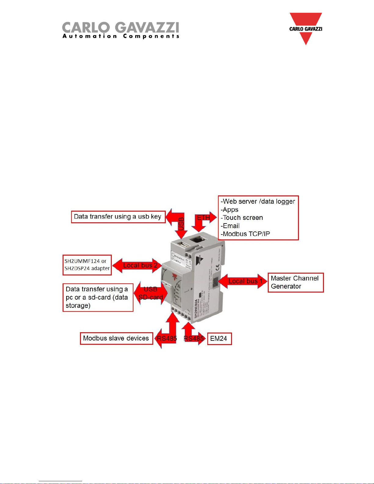
Here below a diagram of the system is shown.
How to install a Sx2WEB system
6
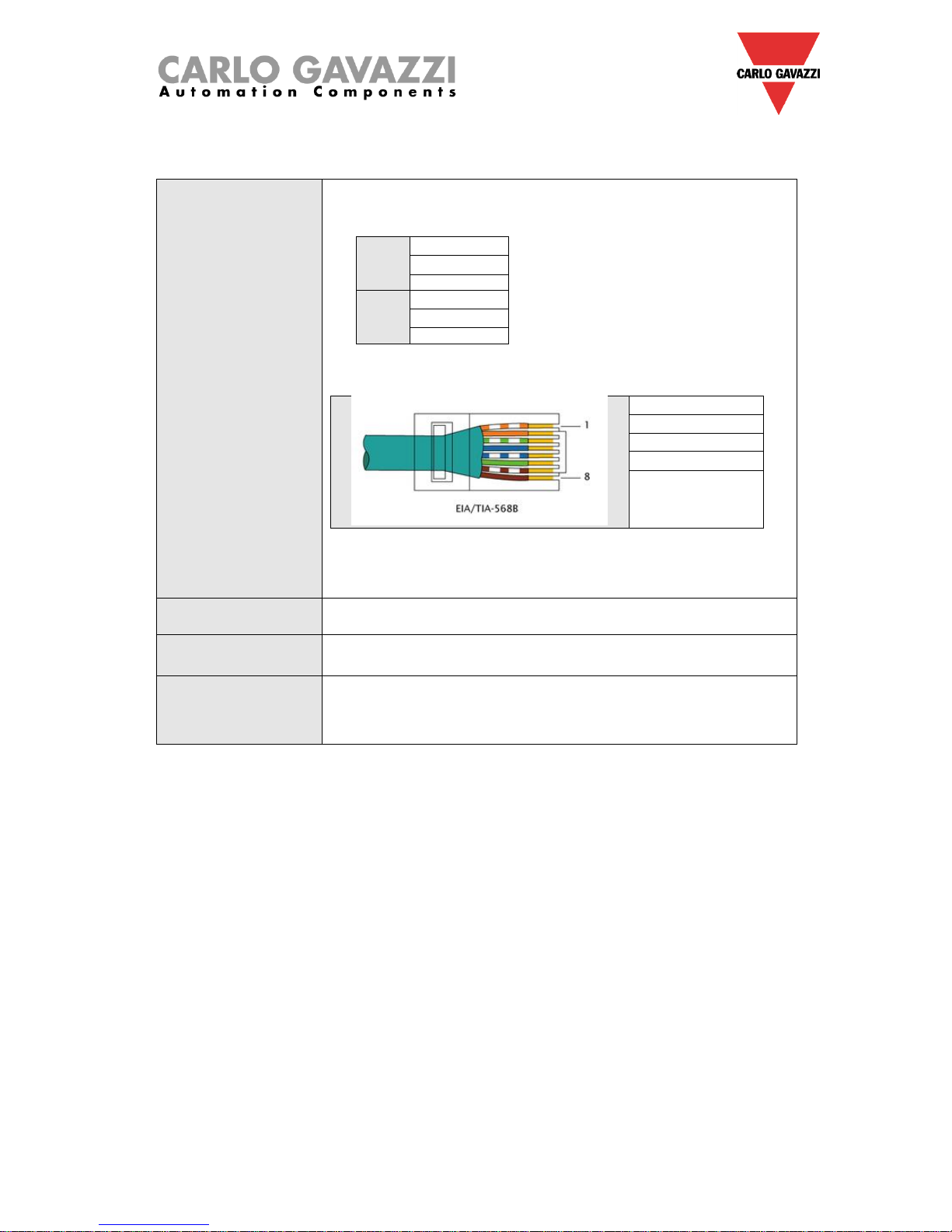
The following table provides a summary of the characteristics of the product:
Ports and connections
1 X 15 to 30Vdc power supply (A1+ and A2-)
2 X RS-485 (COM1 and COM2) :
COM1
Data – (A-)
Data + (B+)
GND
COM2
Data – (A-)
Data + (B+)
GND
1 X RJ-45 connector for 10/100 Base-T Ethernet [Communication]
Pin 1 TX+
Pin 2 TX-
Pin 3 Rx+
Pin 6 Rx-
1 X standard USB
1 X mini USB connection
1 X slot for micro SD or SDHC memory card
Absorption
5W Max.
Operating conditions
-25°C to 40°C
COM port termination
Both COM ports are internally terminated with a value of 150Ω and
polarized with two 511Ω resistors (from “B+” to +5V and from “A-“ to
GND). As a consequence no other external connection is required
from the SX2WEB24 side (see Appendix A for the other termination).
1.1.1 Sx2WEB24 bus description
Local bus 1: This is placed in the connector on the right side and it is called the High Speed bus. This
bus is used to connect the Dupline® generators to the Sx2WEB24.
Local bus 2: This is placed in the connector on the left side and it is a USB bus used to connect to the
universal mobile modem SH2UMMF14
(*)
and to the usb dongle connection module SH2DSP24.
(*)
The SH2UMMF124 is no longer available.
RS485 port 1: This is a serial port used to connect to other third party serial devices.
RS485 port 2: This is a serial port with modbus master capability used to connect to Carlo Gavazzi
energy meters.
USB port: This is placed on the top of the housing and it can be used to change the IP address.
SD-card: It can be only used to change the IP address.
Ethernet port: This is placed on the top of the housing and has to be used to connect to the Sx tool.

How to install a Sx2WEB system
7
The buses can be summarized as shown below.
N.B.: All the connections described in the following paragraphs must be carried out without
power supply.
How to install a Sx2WEB system
8
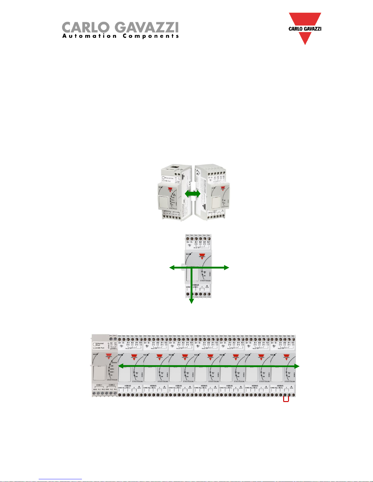
1.2 Bus generators
The Sx2WEB24 (i.e. SH2WEB24 or SB2WEB24) is the brain of the smart-house system but it cannot
work alone and it needs the Dupline® bus generators to send commands to the slave modules and
collect information from them. For this reason, the Dupline® bus generators can be considered as the
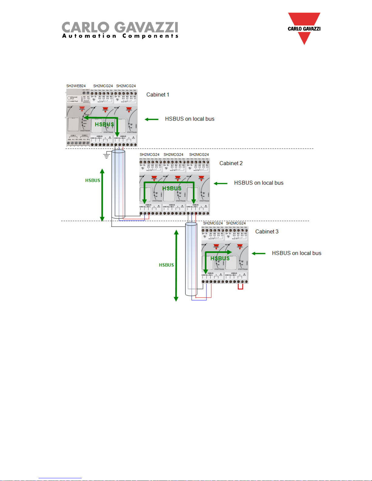
pulsating heart that makes all the information flow. They are connected to the Sx2WEB24 via the high
speed bus that is present both on the local bus and on the terminals at the bottom of the bus
generators. This means that the connection is very fast and easy in a cabinet, since the modules only
have to be plugged together, without any wiring, and at the same time it is very straightforward if the
bus generators have to be mounted in different cabinets. Up to 7 bus generators can be connected to
one Sx2WEB24.
The bus generators can be a mix of the Smart Dupline® generators SH2MCG24, the wireless bus
WiDup generators SH2WBU230N and the Dupline® generator SH2DUG24.
Example 1: The bus generators are all connected in the same Din-rail.
HSBUS
HSBUS
HSBUS
HSBUS
How to install a Sx2WEB system
9
Example 2: The bus generators are mounted in different cabinets.
How to install a Sx2WEB system
10
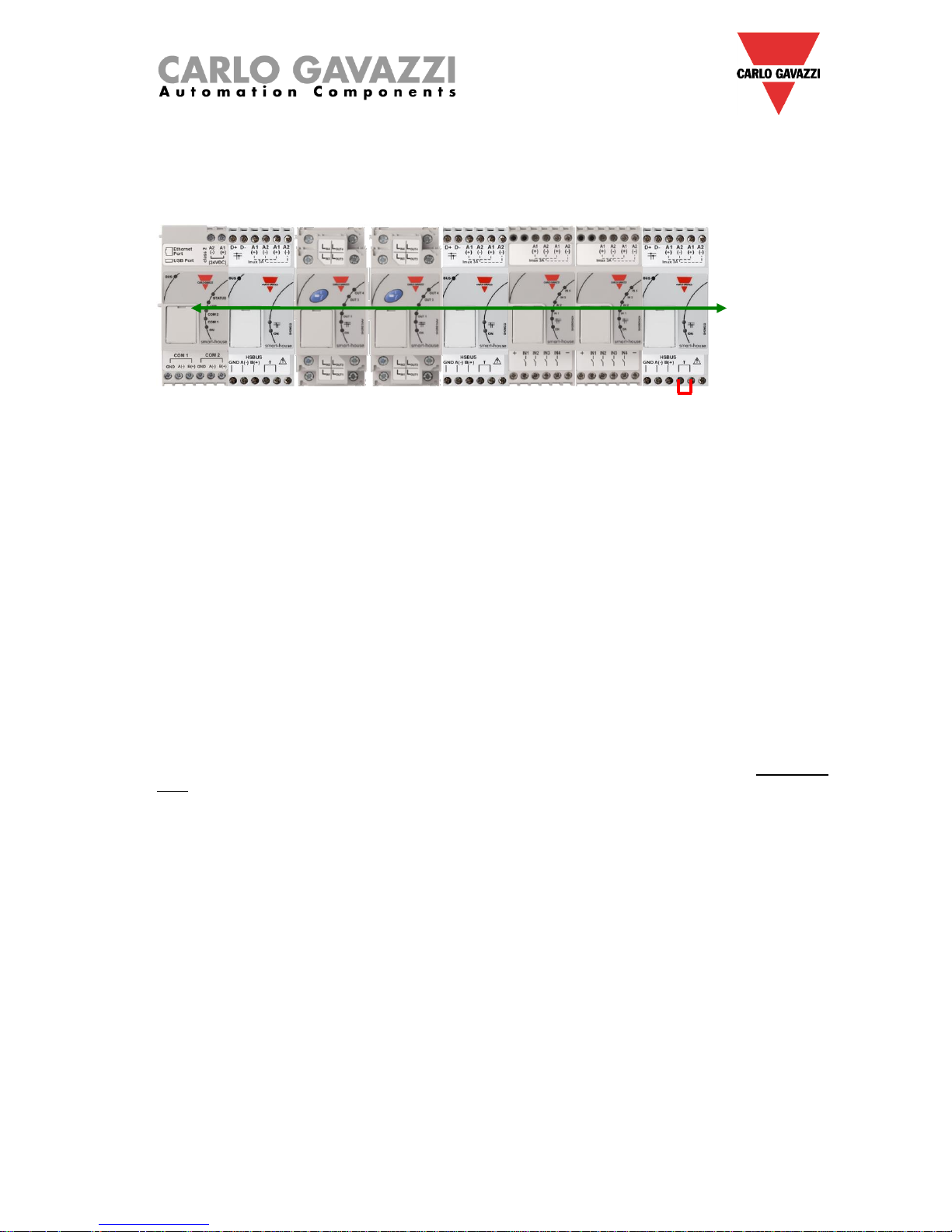
Example 3: The bus generators SH2MCG24 do not need to be put all together in a DIN rail, and they
can be mixed with the Dupline® modules as is shown in the picture below.
Sx2WEB24 SH2MCG24 SH2RE16A4 SH2RE16A4 SH2MCG24 SH2INDI424 SH2INDI424 SH2MCG24
Also in this case there is no need to wire the RS485 for the HS speed bus since the local bus connector
of the Dupline® modules is transparent to it. The installer only has to terminate the HS speed bus in the
last bus generator of the RS485 network.
1.2.1 Wiring the high speed bus
The high speed bus is an RS485 serial interface, at 256Kbit/s
The cable
The RS485 communication cable is a shielded, twisted pair cable. Many cable manufacturers supply
cable meeting the RS485 standard. Other cabling, such as telephone cable, coaxial cable and multicore wires should not be used as they could prove problematic and not provide satisfactory
performance.Cables must be at least 0.5 mm.
Topology
The cable must be installed to pass close by each node. Stubs (cables joining the node to the
cable),stars(multiple cable segments brought back to a single point) or loops must not be used.
Cable length
The maximum length of the cable is 600 metres.
Connection of the cable shield
The shield of the RS485 cable establishes a reference voltage for the RS485 signal conductors.
The "screen pig-tails" going into the terminals should be as short as possible. The shield should be
continuous throughout the installation, the best way is to connect the shield to earth ground in only one
point as nearest as possible to the SH2MCG24 (the best is on the terminal where the cable is
connected). This connection is not to be shared with other devices which could add external noise or
disturbance.
Termination
The network must be terminated at the end on the last bus generator of the network (see the T
terminals in the picture above) while it has already been terminated on the Sx2WEB24 side. This is to
avoid reflections which would disrupt communication.
Cable Insulation
The communication cable must not be run in cable trays carrying power wiring nor in close proximity to
power wiring. Current surges in power wiring due to high equipment starting currents or to faults can
disrupt communication.
For more details please see appendix A.
HSBUS
How to install a Sx2WEB system
11
1.2.2 The Dupline® bus
The Dupline® bus is a signal transmission system that reduces the need for wires, as compared to an
ordinary installation. Using only 2 wires, the information can be transmitted from up to 2 km away. Many
input and output modules are supplied from the same 2 wires. Both digital (on-off) and analogue (e.g.
temperature, light level, wind speed and other) data is present on the bus at the same time and it is
collected by the SH2MCG24 and then processed by the Sx2WEB24.
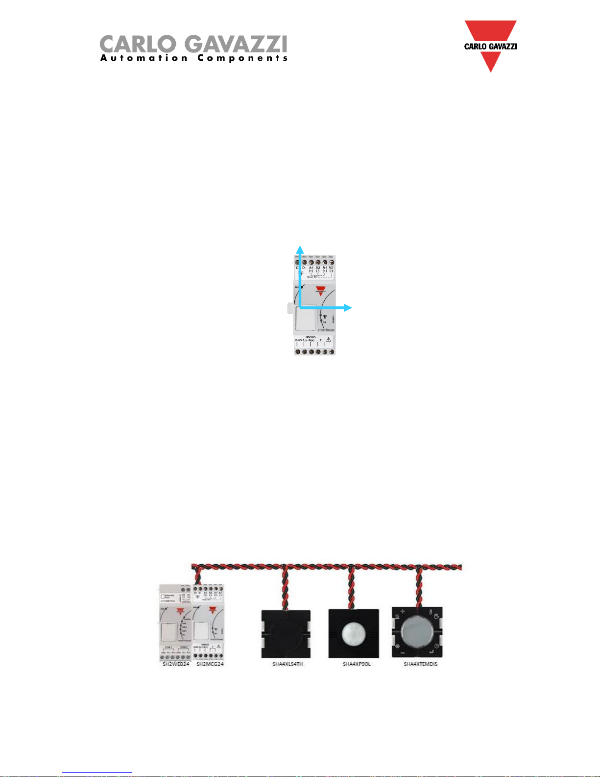
The SH2MCG24 is the smart Dupline® bus generator that powers the Dupline® bus onto the local bus
and onto the terminals at the top. All the Dupline® slave modules have to be connected to one
SH2MCG24 to be part of the smart-house system.
The SH2MCG24 is powered by 15 to 30Vdc.
The Dupline® modules in the smart-house system can be divided into two groups:
- Decentralized modules: these are all the modules such as light switches, PIR sensors, lux
sensors, decentralized I/O modules, etc. which are mounted into the wall boxes or on the wall
- Centralized cabinet modules: these are the ones housed in the 1-DIN or 2-DIN housing for din
rail mounting
All our decentralised Dupline® devices are connected to each other with a single 2-wire cable. This
cable carries the communication signal that comes from the bus generator SH2MCG24. These 2 wires
carry a DC low-voltage pulsating signal, and therefore attention must be paid to keep the correct
polarity of the connection.
The Bus is overload and short-circuit protected, but anyway it is a good rule to avoid to invert
the polarity.
The modules cannot withstand voltages other than the Dupline® signal voltage (5.5V to 10V).
Dupline® bus
Dupline® bus
How to install a Sx2WEB system
12
The so-called decentralised modules can be divided into the following groups:
- Light switches
- PIR sensors
- Temperature displays
- Water and smoke detectors
- Wind sensors
- Humidity sensors
- Light sensors
- Decentralised input/output modules
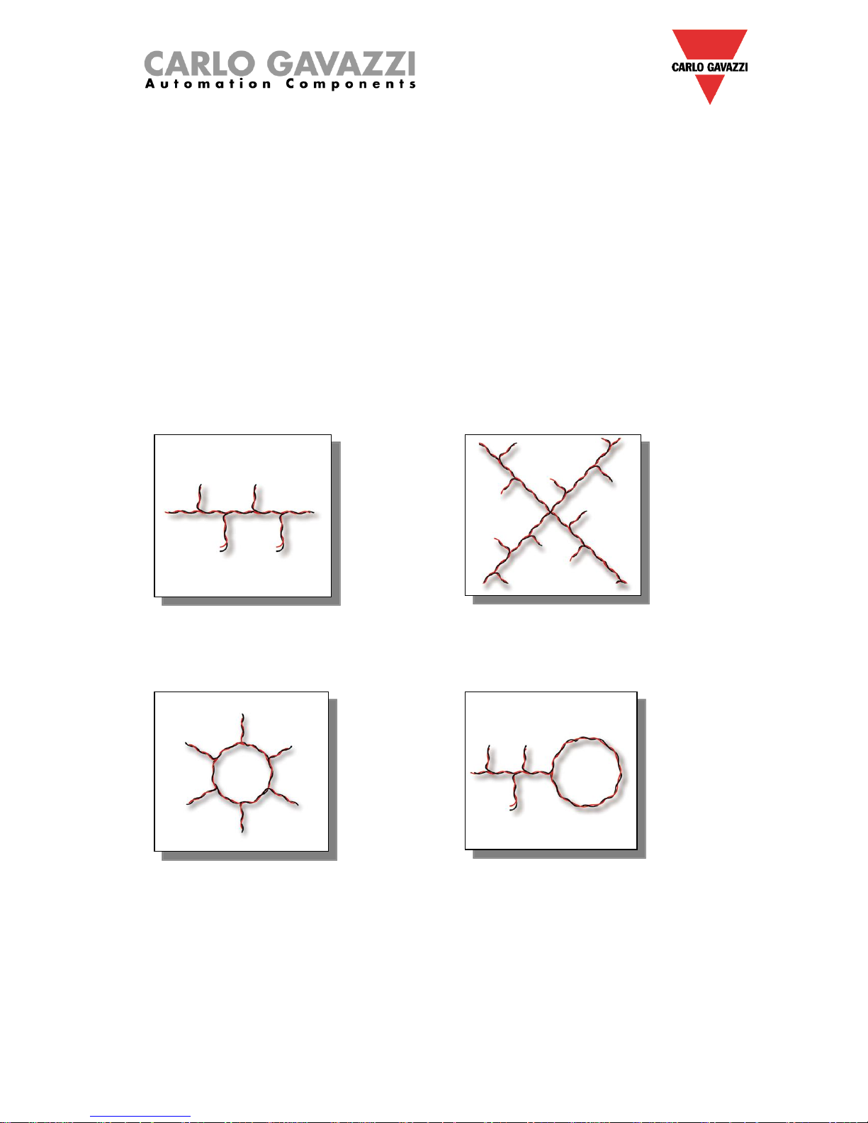
The installation is not to be engineered around the Dupline® bus because it can be matched to the
application. The routing of the cable may be in a line, star, ring or any combination.
Straight-through: the best
place for the SH2MCG24
would be in the middle of the
line
Star: the best place for the
SH2MCG24 would be in the
middle of the star
Ring: the best location for the
SH2MCG24 is in the middle
between the two farthest
distant modules.
Combined: the best location
for the SH2MCG24 is in the
middle between the two
farthest distant modules.
How to install a Sx2WEB system
13
1.2.3 Cable and installation tips
1.2.3.1 New Installation Planning
When planning a new installation, a generic Bus cable can be used: it is better to use a twisted cable in
order to prevent electrical noise from affecting one conductor more than the other and thereby creating
an unbalanced Dupline® system.
In the case of very noisy installations (with noise sources such as contactors, inductive loads etc) we
recommend the use of a shielded cable.
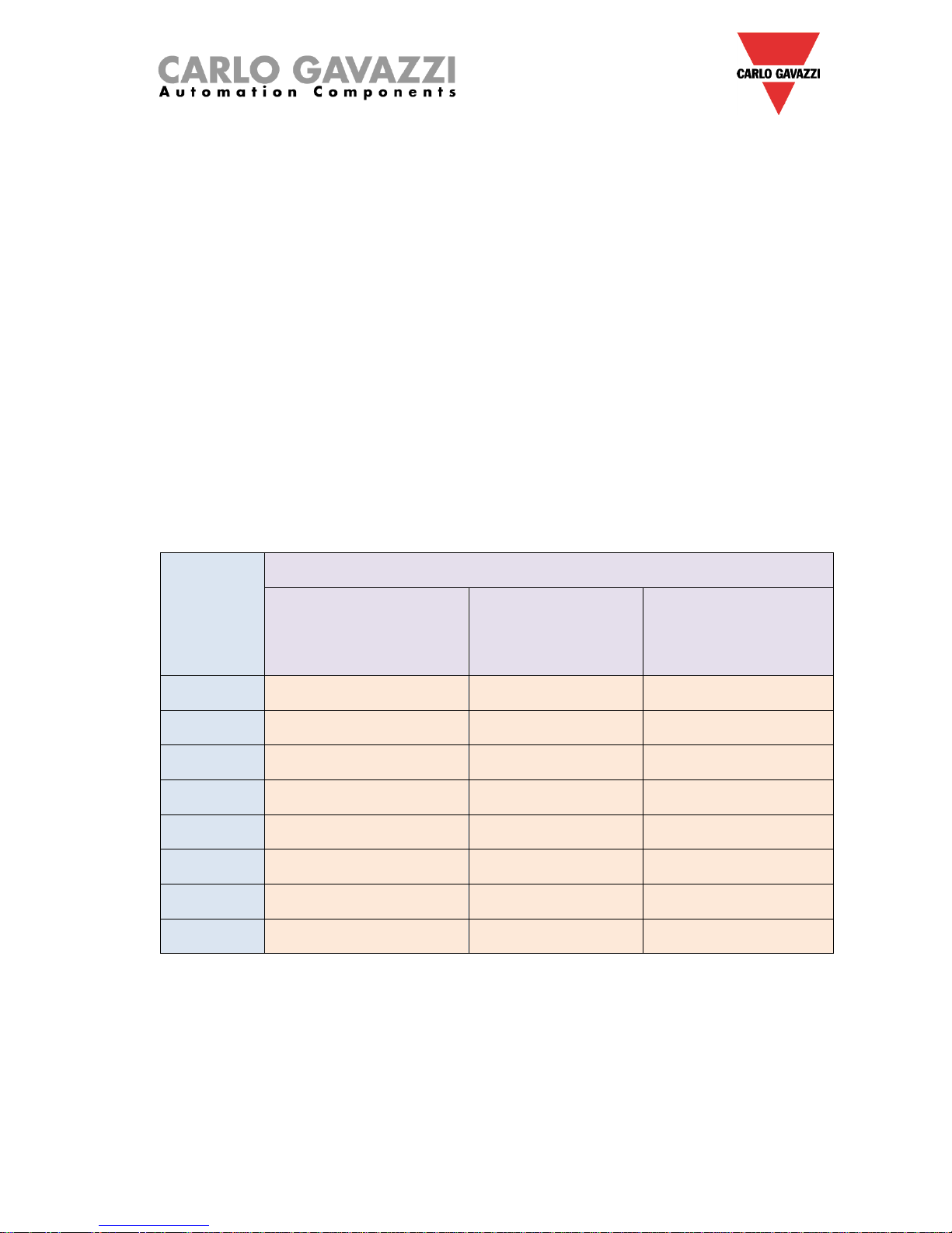
The table below can be used to find the right cable: this can easily be carried out by considering the
maximum distance between the SH2MCG24 and the farthest module in the installation and checking
the table below.
The values shown in the table have been calculated considering a balanced distribution of the modules
in the Dupline® bus.
Installations where most of the modules are placed at the end of the network may be critical and this is
not recommended (the table is not valid in this case).
The values shown in the table are also suitable for installations where the majority of the modules are
placed at the beginning of the network (close to the SH2MCG24); this type of connection represents the
best configuration to guarantee the best performance of the system.
Table of cable sections:
Max current
Consumption
Cable size
0.75 mm2 (AWG 19), twisted
1 mm2 (AWG 17),
twisted
1.5 mm2 (AWG 15), twisted
450 mA
50 m
70 m
100 m
350 mA
65 m
90 m
130 m
300 mA
75 m
100 m
150 m
250 mA
90 m
120 m
180 m
200 mA
115 m
150 m
230 m
150 mA
150 m
200 m
300 m
100 mA
225 m
300 m
450 m
50 mA
450 m
600 m
900 m
The user is recommended to select cables according to the length and consumption shown in the table
above. It is also advisable to use polyethylene conductor insulation to have lower cable capacitance.
The total consumption of all the modules supplied by the Dupline® bus (e.g. light switch, PIR, lux
sensors) and the cable resistance affect the voltage of the Dupline® bus.
The drop in the Bus voltage might cause the modules placed far from the SH2MCG24 to not work
correctly.
 Loading...