

Page 1
2-10 Specifications are subject to change without notice (30.11.2001)
Control input
In most SSRs galvanic separation is
achieved by optocouplers. These optocouplers, equipped with integrated trigger
circuit (optotriac), provide the switching
function required for the corresponding
load type.
We distinguish between:
- ZS: Zero Switching
- IO: Instant-on Switching
- PS: Peak Switching
- AS: Analog Switching
- DCS: DC Switching
- FS: Full Cycle Switching
Types of SSRs
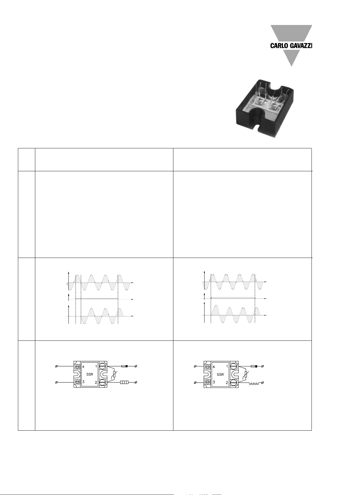
When applying the control voltage, the AC SSR output is activated
at the first zero crossing of the line voltage. The response time is
hereafter less than a halfperiod, i.e. typically below 10 ms at 50 Hz.
ZS SSRs are employed in a host of applications with resistive loads
(temperature control) and control of incandescent lamps. The ZS
types are the most commonly used SSRs due to their extensive use
with plastic moulding machines, packing machines, soldering machines as well as machines for the food processing industry.
ZS SSRs are used in various applications, such as interfacing resistive loads or lighting installations. Due to high surge current- and
blocking voltage capabilities, SSRs of this switching type will also
perform successfully with most inductive and capacitive loads.
Zero Switching SSR (ZS)
For resistive, inductive or capacitive loads
Control
input
Fuse
Varistor
Load
Function
Application
Description
Solid State Relays
General Information
Instant-on Switching SSR (IO)
For inductive loads
The SSR output is activated immediately after applying control voltage.
Consequently, this relay can turn on anywhere along the AC sinusoidal
voltage curve. The typical response time is thus less than 1 ms.
(Relays equipped with reed contacts are inherently instant-on types.)
This SSR is particularly suitable in applications where a fast response
time or phase angle control is desired.
Control
input
Fuse
Varistor
Inductive load
Line
voltage
(VAC)
Control
input
Load curent
(AAC)
Line
voltage
(VAC)
Control
input
Load current
(AAC)
t
t
t
t
t
t
Type
Note: For SSR without integrated voltage protection
Page 2
Specifications are subject to change without notice (30.11.2001) 2-11
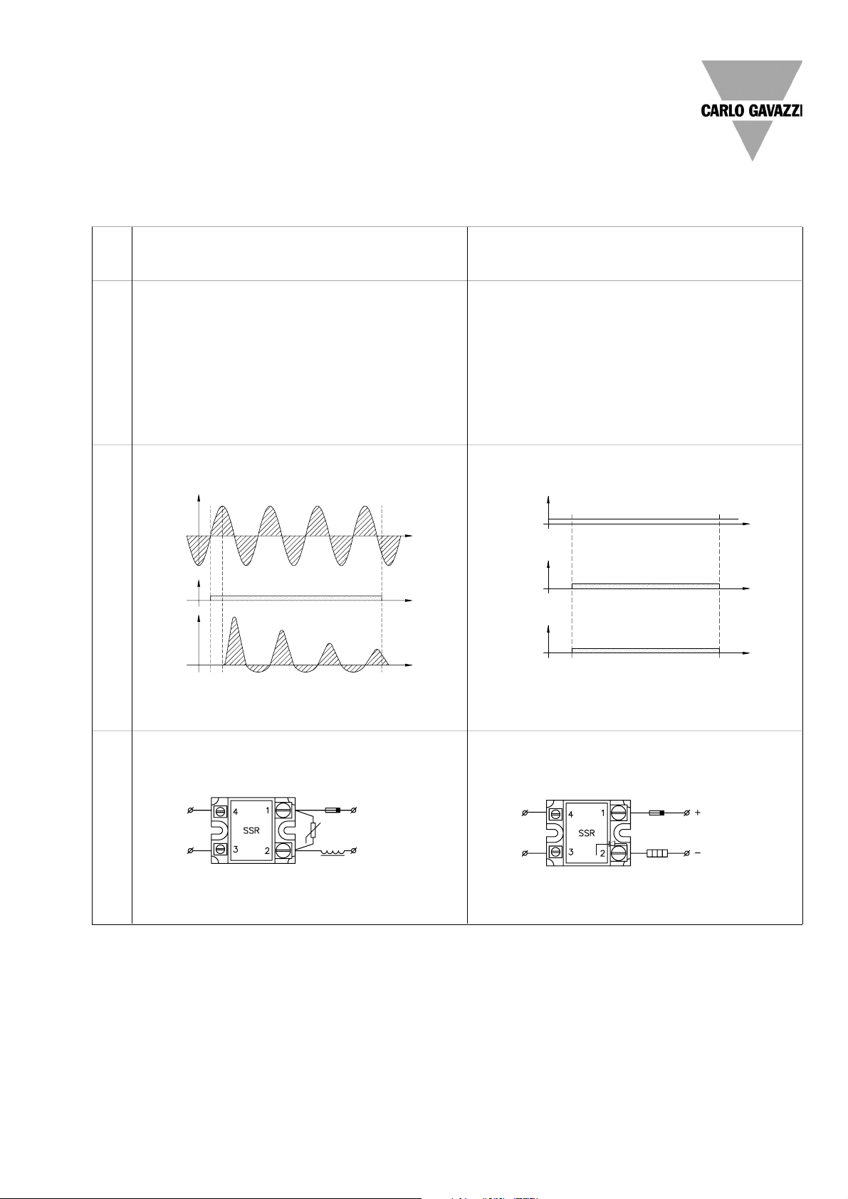
DC Switching SSR (DCS)
For resistive and inductive loads
The power semiconductor in the DC switching relay operates in accordance with the control input status. The response time is less
than 100 µs.
DCS SSRs are used with resistive and inductive loads for the control
of DC motors and valves.
When switching inductive loads it will be necessary to interconnect
a free wheeling diode surplus voltage parallel to the load as protection.
Control
input
Fuse
Load
Line
voltage
(VAC)
Control
input
Load
Current
(AAC)
Line
voltage
(VAC)
Control
input
Load
Current
(AAC)
Solid State Relays
General Information
Types of SSRs (cont.)
Function
Application
Description
Type
Peak Switching SSR (PS)
For inductive loads with remanent iron core
The peak switching SSR is designed in a way that the power output
is activated at the first peak of the line voltage upon application of
the control voltage. After the first half period the PS SSR operates as
an ordinary ZS relay. The peak of the inrush current could hereafter
be reduced during the first half-period for inductive loads.
Control
input
Fuse
Varistor
Inductive load
t
t
t
t
t
t
Page 3
2-12 Specifications are subject to change without notice (30.11.2001)
Types of SSRs (cont.)
Solid State Relays
General Information
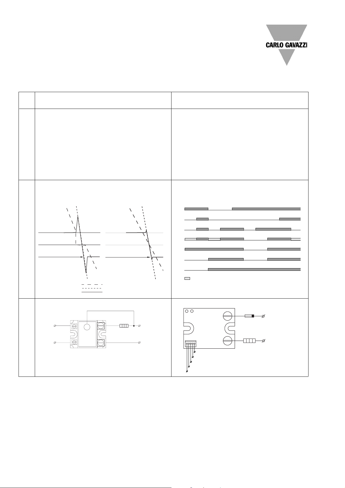
Low Noise SSR (LN)
For resistive and inductive loads
System Monitoring SSR (SM)
For resistive and inductive loads
The Low Noise SSR is designed for light industrial environments and
fulfills the generic emission standard EN50081-1. By controlling the
switching mode of the semiconductors, the peak level of the zero
voltage turn-on is minimised, thus reducing the noise emitted by the
SSR.
Low Noise SSRs are particularly suitable for applications where electromagnetic noise must be limited to avoid interference with other
equipment. In this kind of environment, noise generated by standard
SSRs is considered critical or unsafe. Low noise SSRs can be used
with both resistive and inductive loads.
The system monitoring (sense) SSR provides an alarm output in the
event of a circuit failure. Internal circuits monitor:
- line voltage
- load current
- correction functioning of the SSR
- SSR input status.
The relay is designed for applications where immediate fault detection is required. An alarm output signal is available to determine fault
status.
Function
Application
Description
Type
Holding Current Level
Zero Voltage
Noise Decreased Drastically
Holding Current Level
Zero Voltage
Peak that Generates Noise
Normal
Relay
OFF
Operation
Relay
ON
Line
Voltage
Loss
Line
Voltage
Loss
Load
Open
Circuit
DC
Supply
Loss
DC
Supply
Loss
Relay
Remains
OFF
Shorted
Relay
Shorted
Relay
Line
Voltage
Load
Current
Control
Green
LED
DC
Supply
Red
LED
Alarm
Output
(normally open type)
=Half LED light intensity
~
S
41
32
SSR
Control
Input
N/L
2
L
1
Note: Connection “S” does not apply to SSRs
with integrated heatsink
3+
4-
5 Not Con.
6 Control (High/Low)
7 Alarm (PNP/NPN)
Fuse
Load
L
2
/N
L
1
1
2
On
Alarm
Load Current
Phase
Voltage across SSR
Normal Zero Switching
Low Noise Zero Switching
Page 4
Specifications are subject to change without notice (30.11.2001) 2-13
Solid State Relays
General Information
Types of SSRs (cont.)
Power output
Depending on the application, various
questions concerning the power output
of the SSR need to be clarified. The most
important parameters are
- Line voltage (load voltage)
- Load current
- Type of load (application)
in order to be able to select the correct
SSR. To avoid unnecessary maintenance
expenses, the selection needs to be as
accurate as possible.
Line voltage
The voltage range of an SSR must be selected according to the line voltage in the
application. For the non-repetitive peak
transient voltage of the SSR, both transients from the mains and voltage peaks
from the application need to be considered.
A corresponding protective element like
a freewheeling diode (only DC), a varistor
or a snubber (RC) can be incorporated in
order to protect the output semiconductor.
Load current
The relay must be selected in a way that
the continuous load current in the application does not exceed the corresponding nominal value of the relay. It is important to take into consideration the continuous load current in relation to the ambient temperature. With inductive loads,
such as motors, valves, etc., the SSR
must be sized or selected according to
the highest expected surge current.
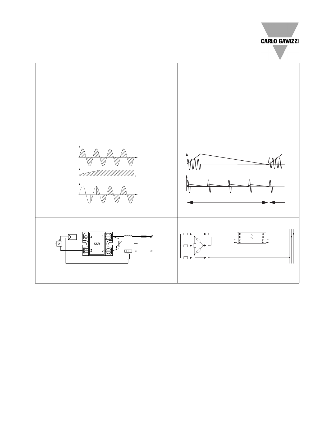
Since the control input of the analog relay - according to specifications 4 to 20 mADC - can be varied, the output operates in
accordance with the phase control principle. The relay is
equipped with a built-in synchronization circuit in order to
achieve phase angle control. The output is proportional to the
input voltage or input current. The transfer function is linearized
and reproducible.
These SSRs are highly advantageous in closed loop applications
or where soft starting can limit high inrush currents.
The Full Cycle SSR uses an analogue switching principle that
provides a number of full cycles that are evenly distributed
over a fixed time period. The number of cycles switched during the time period is directly proportional to the control input
applied to the SSR.
Since the full cycles are distributed, this SSR provides high accuracy in temperature control and creates less noise.
Compared to conventional Burst control, the Full Cycle SSR
reduces the stress on the load by limiting the band within
which the load cycles.
Analog Switching SSR (AS)
For resistive, inductive or capacitive loads
Control
circuit
Inductor
Fuse
Varistor Capacitor
Load
Temp. sensor
Line
voltage
(VAC)
Control
input
Load current (AAC)
t
t
t
Full Cycle SSR (FC)
For resistive loads
Function
Application
Description
Type
Burst Full Cycle Switching
Analogue Full Cycle Switching
Period
T
T
Supply
(V type only)
T
1
A
3
A
4
T
2
L
1
A
1
A
2
L
2
L
1
L
3
L
2
SSR
+
-
Analogue
Control
Input
I/V type
Page 5
2-14 Specifications are subject to change without notice (30.11.2001)
Types of SSRs (cont.)
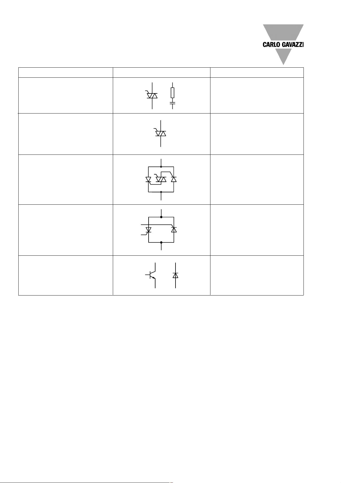
Snubberless Triac
The snubberless triac is a further development of
the triac in which the two thyristors on the chip are
well separated. Consequently, a higher dV/dt capability is achieved.
In this way the internal snubber can be eliminated.
Alternistor
The alternistor is developed especially for industrial use. The alternistor consists of two antiparallel
thyristors and a gate triac integrated in the same
chip. The thyristors are well separated. The triac
will block uncontrolled turn-on during commutation.
Triac
The triac consists of two antiparallel thyristors
mounted on the same chip in order to give fullwave operation at a single gate.
A snubber is often mounted across the SSR in
order to reduce the dV/dt.
Thyristor (SCR)
The antiparallel thyristor solution is most common
for industrial SSRs. The solution requires two separate SCRs and two trigger circuits, which give
optimum dV/dt capability.
Transistor
The transistor option - often the open collector
configuration - is used in the DC SSRs. A freewheeling diode is normally mounted across the
transistor to avoid damage from back-EMV from
inductive loads.
The triac SSR is the most cost-effective solution in
applications with low dV/dt demands, e.g. applications with heating elements with almost constant
resistance.
The snubberless triac is one of the latest improvements from semiconductor manufacturers.
The elimination of the snubbers also reduces the
leakage current in the switching circuit.
The snubberless triac is common in resistive and
inductive applications (up to 25 A) .
The alternistor output is widely used in SSRs for resistive and inductive loads.
The antiparallel SCR SSR is used for all load types,
such as resistive, inductive and even capacitive
loads.
An SCR in a diode bridge is only used in PCB relays
with load currents of less than 2 A.
The transistor is used for DC loads such as DC
motors, solenoids or valves.
Load switching component Symbol Application
Solid State Relays
General Information
Advantages and Limitations
SSRs offer the user many outstanding
features and should be treated as a separate class of relay. However, due to the design of SSRs, the user is always faced
with a few limitations which are different
from those of electromechanical relays
(EMR). The following outline of advantages and limitations of SSRs will serve as
a guide to the professional use of these
devices.
Advantages
* Long life and high reliability - more than
10
9
operations
* No contact arcing, low EMI, high surge
capability
* High resistance to shock and vibration
* High resistance to aggressive chemicals
and dust
* No electromechanical noise
* Logic compatibility
* Fast switching
* Low coupling capacitance
Long life and high reliability
In SSRs from Carlo Gavazzi an optimized
thermal design is achieved by applying
the "Direct Copper Bonding" technology.
This technology finally eliminates the
thermal fatigue between chip (silicon) and
terminals (copper). Furthermore, it reduces the thermal resistance between
junction and ambient.
The DCB substrate, on which the chip is
soldered, consists of a ceramic insulator
(Al
2O3
) with a layer of copper (Cu) on both
sides. The copper is bonded with the ceramic material in order to get similar thermal expansion conditions for both materials. Thereby the mechanical stress between silicon chip and copper will be minimized while the relay is in operation.
The ceramic material provides a 4 kV insulation between copper leads and
heatsink. A lower temperature difference
(∆T) on the junction will increase the lifetime of the relay, and an increase of the
switching frequency can help to achieve
a more reliable application.
No contact arcing
No contact arcing will occur since switching takes place inside the semiconductor
material, which changes from a non-conductor to a conductor at the signal of the
control input. Line and load radiation are
reduced considerably because the SCRs,
alternistors or triacs are basically current
latching devices, which will turn off as
soon as the current is near zero. This is
known as "zero crossing turn off". This
greatly reduces the radiated electromagnetic interference (EMI), and this reduction of EMI is often well received by the
equipment designers.
High resistance
SSRs with optocoupler inputs are fully
embedded in the housing material and
consequently, since no moving parts are
used, they are highly resistant to vibrations and shock.
Page 6

Specifications are subject to change without notice (30.11.2001) 2-15
Advantages and Limitations (cont.)
Switching characteristics of EMR and SSR
Control inputControl input
Load voltage
Load voltage
Control voltage
SSR
EMR
Reaction
time
Bounce
time
Reaction time < 1 ms (IO)
< 10 ms (ZS)
Solid State Relays
General Information
High resistance to aggressive
chemicals and dust
Neither sand, dust nor aggressive chemicals can disrupt the trouble-free operation of a Solid State Relay.
No electromechanical noise
SSRs do not create mechanical noise
since everything is controlled entirely
electronically. In applications such as office machinery or in medical equipment
this is for the benefit of the user.
Logic compatibility
SSRs are available with input circuits
which are directly compatible with logic
components for CMOS, TTL, microprocessors or analog circuits.Logic compatibility is important since SSRs are often directly controlled by PLCs or other logic
outputs. High-current SSRs can be driven
with minimal currents of less than 10 mA
@ 24 VDC.
The direct copper bonding technology
Al2O
3
Si
Solder
Cu
Al
Logic compatibility to PC/PLC
Fast switching
Instant-on SSRs feature a turn-on time of
less than 1 ms. This fast switching capability makes it possible to phase angle
control the power output by means of an
external control circuit. In the analog
switching relay this function is already
built-in.
Low coupling capacitance
The very low coupling capacitance between input and output of SSRs is inherent in the optocoupler used in most SSR
designs. The resulting lower off-state
leakage current is important in medical
applications, office machinery, household
appliances or in industrial applications.
Limitations
* Contact voltage drop
* Finite transient voltage resistance and
dV/dt limitations
* Leakage currents and dI/dt limitations
Contact voltage drop
The contact voltage drop across the
thyristor is usually 1 to 1.6 V. Voltage drop
application. The energy absorption of a
disc varistor is always proportional to its
size. Therefore it is recommended to use
varistors with a diameter of minimum 14
mm for PCB SSRs and 20 mm relays for
chassis mounting.
Limitations due to rapid voltage
change
The junction of any semiconductor exhibits some capacitance. An alternating
voltage imposes capacitance on this
junction, which results in a current where
I = C x dV/dt.
If this current is sufficiently high, a regenerative action may occur causing the
SCR to turn on. This regenerative action
is similar to the gate turn-on.
The expression "dV/dt" defines a voltage
change in relation to time. It is usually given in volts per microsecond (V/µs).
together with load current are basic figures for the calculation of the power losses. Excessive heat can easily destroy the
power semiconductor. It is therefore indispensable to calculate the power dissipation and to use adequate heatsinking.
Finite transient voltage resistance
The AC mains contains all kinds of voltage spikes and transients. These transients may result from other components
like motors, solenoids, switches, transformers or contactors - not to mention external sources such as lightning.
If overvoltage protection is not provided,
the thyristors used in SSRs might exceed
their breakdown voltage and will turn on
for less than a halfperiod. The nonrepetitive peak voltage is the maximum
off-state voltage which the output switching device can withstand without switching on.
Whenever they are not built-in, varistors
for transient voltage protection should be
fitted across the output. The varistors
must be rated for the line voltage in the
Page 7

2-16 Specifications are subject to change without notice (30.11.2001)
Advantages and Limitations (cont.)
Heat dissipation from contact voltage drop
Heat
Chip
Current
↑∆V
Solid State Relays
General Information
Off-state dV/dt
The off-state dV/dt is the parameter defining the voltage rise capability of the SSR,
i.e. the max. allowable rate of increase in
voltage across the output terminals which
will not switch on the SSR. Typically it lies
within the range of 100 to 1000 V/µs.
Commutating dV/dt
The dV/dt is expressed in volts per microsecond (V/µs) and indicates the rate of
voltage rise which the SSR output switching device can withstand without being
turned on again as long as the load is off.
The commutating dV/dt rating of an SSR
is a measure of its ability to switch off an
inductive load.
With the current crossing zero and turning off the load, the voltage rise across the
output semiconductor could, due to too
high dV/dt, immediately turn on the SSR
(without applying control voltage).
Consequently, with inductive loads,
where the phase shift between current
and voltage is large, the chance of an
exceptional dV/dt value is very high.
Snubber
With a high load inductance, a very common method to eliminate random firing
through interference, or spontaneous refiring through commutating dV/dt, is to
connect an RC network, known as "snubber", across the SSR terminals. The capacitance (C) in conjunction with the impedance of the load attenuates the voltage waveforms transmitted via the mains
or occuring when switching on an inductive load.
used, or the circuit may actually be
touched, say for servicing. A resistor
across the indicator and a line safety
breaker are the standard means by which
these limitations can be overcome.
dI/dt limitation
The rate of rise of current (dI/dt) is normally assumed to be low compared with
the time required for the thyristor to reach
full on-state conduction. In installations
there is a certain amount of inductance
which limits the rate of rise of current. In
the SSR data sheet the dI/dt is given. The
dI/dt usually lies within the range of 10 to
100 A/µs. The necessary inductance can
be calculated as follows:
The inductance of the load, the supply
and all power cables in between need to
be considered as well.
Standard values are:
R < 100 Ω, C < 0.22 µF.
Most of the modern SSRs from Carlo
Gavazzi have such a high dV/dt capability that the snubber can be eliminated.
Off-state leakage current
SSRs always have off-state leakage currents. The thyristors, control circuitry and
snubber network all supply small off-state
currents, which usually total from about 1
to 10 mA rms.
These leakage currents should be taken
into account when either indicators are
Remedies
In order to achieve proper function and a
reliable application the user should consider:
1. A heatsink to remove the dissipated
power
2. A varistor to protect against overvoltage transients
3. A fuse to limit current passing through
the SSR thus resulting in:
a. short-circuit protection
b. overload protection
4. Self-induction in the system must be
sufficiently high, in order to limit dI/dt.
5. A circuit breaker to disconnect mechanically the SSR application from
the mains (safety measure).
Snubber circuit
Load
current
Control
input
SSR
∆ voltage
t
t
t
dV/dt
U
p
[V]
The dV/dt caused by phase shift
Rate of rise of voltage - the dV/dt
∆V
time [µs]
dV/dt ≈
∆t
∆V
0.63 x U
p
τ
≈
Up[V]
∆ t ≈τ
Page 8

Specifications are subject to change without notice (30.11.2001) 2-17
Solid State Relays
General Information
1. General Information
Load current, line voltage, ambient temperature and load
type are crucial factors when
using Solid State Relays. It is
necessary to carry out a critical
analysis of the application and
perform proper calculations
when using all Carlo Gavazzi
Solid State Relay products.
2. Overload Protection
The relay must be protected
against overload (short-circuit) by means of an external
semiconductor fuse. Carlo
Gavazzi provides the basic
calculation to help you select
the right fuse.
3. Voltage Transient
Protection
Ideal protection is achieved
through varistors (metal oxide
varistors) mounted across the
power semiconductor. The
varistor voltage has to match
with the line voltage in your
application. Wrong selection
can cause limited protection
or a hazardous situation. On
a number of models, the
varistor is already mounted
internally.
4. Overheat Protection
The relay must be protected
effectively against excessive
heat. Thermal stress will reduce the lifetime of your SSR
drastically. Therefore it is
necessary to choose the appropriate heatsinks, taking
into account ambient temperature, load current and
duty cycle. A thin film of thermally conducting compound
will reduce the thermal resistance between the relay and
the heatsink.
Important matters to be observed when installing an SSR:
When installed properly, the Solid State Relay will last millions of operations
Heatsink
Fuse
Varistor
Application
When looking for a relay to solve your
switching application requirements, you
should consider the advantages of SSRs
and how to deal with the limitations.
A. Heating systems
Electric ovens
Soldering systems
Plastic processing systems
Galvanic systems (electro-plating)
Film developing systems
Packaging industry
Rubber industry
Cooking systems
B. Optical equipment and systems
Photocopiers
Light equipment
Traffic light controls
C. Electric motor drives
Position control X-Y
Valve positioning
Soft starting, braking, reversing
D. Transformer supply
Welding equipment
Light systems with transformer
supply
Varistor
Ultrafast
Fuse
(20mm)
Ultrafast
Fuse
Varistor
(20mm)
Varistor
Ultrafast
Fuse
(20mm)
Varistor
Ultrafast
Fuse
(20mm)
Page 9

2-18 Specifications are subject to change without notice (30.11.2001)
Solid State Relays
General Information
Insulation
Insulation
Rated insulation voltage
Input to output ≥ 4000 VACrms
Rated insulation voltage
Output to case ≥ 2500 VACrms
Insulation resistance
Input to output ≤ 10
10
Ω
Insulation resistance
Output to case ≤ 10
10
Ω
Insulation capacitance
Output to case ≤ 8 pF
Insulation capacitance
Input to output ≤ 50
Insulation resistance
output to case
Dielectrical strength and
insulation resistance, capacitance from output to case
(heatsink).
Insulation resistance
input to output
Dielectrical strength and
insulation resistance, capacitance between input and
output.
Insulation resistance (output to case)
This is the rated insulation and, consequently, when the SSR is mounted on an
external heatsink, the heatsink must be
connected to protective earth (PE).
Insulation resistance (input to output)
Depending on the applied input voltage,
the input voltage insulation is either rein-
forced or rated insulation.
A. When the input voltage is ≤ 25 VACrms
or ≤ 60 VDC, there is reinforced in-
sulation between input and output.
This means that the input voltage can
either be PELV (protected extra low
voltage, PE connected) or SELV (special extra low voltage, unprotected).
B. When the input voltage is higher than
the voltages defined under A and ≤ 50
VAC or ≤ 120 VDC, there is reinforced
insulation between input and output.
This means that the input voltage can
be FELV (functional extra low voltage,
PE connected).
C. When input voltages are higher than
those mentioned under A and B, they
are regarded as line voltage inputs
and, consequently, there is only rated
insulation between input and output
in this case.
Protective earth connection (PE)
Where protective earth (PE) is connected
to the input, either of the two input terminals can be used. In the case of heatsink
mounting versions the heatsink must be
connected to protective earth (PE) due to
the rated insulation. This procedure is in
accordance with IEC 60204-1, EN 60204-1,
VDE 0113T1 and other important international application standards.
Electrical build-up
Safety regarding clearance, creepage
and insulation barriers is based on the latest international coordination standards
IEC 60664, 60664-1.
Page 10

Specifications are subject to change without notice (30.11.2001) 2-19
Housing Specifications
Weight Approx. 110 g
Housing material Noryl GFN 1, black
Base plate Aluminium
Potting compound Polyurethane
Relay
Mounting screws M5
Mounting torque ≤ 1.5 Nm
Control terminal
Mounting screws M3 x 6
Mounting torque ≤ 0.5 Nm
Power terminal
General Specifications
Standards
To ensure the widest possible scope of application in electrical equipment and machinery, Carlo
Gavazzi's SSRs are designed in accordance
with the following standards:
IEC 60158-2, 60204-1, 60947-1, 60947-4,60529
CSA C.22.2.14
UL 0508, 0840
VDE 0805, 0750, 0700
Housing Specifications
Material
Housings and potting compound are UL-approved and flame, heat and impact resistant.
Protection against electric shock
Terminal protection against direct contact.
Degree of protection (IEC 60529)
IP 00 Non-protected
IP 10 Back-of-hand protected
IP 20 Finger-protected
The technical specifications of the degree of
protection are in accordance with IEC 60529
(IEC 60947-1).
General Specifications
Operational voltage range 24 to 280 VACrms
Non-rep. peak voltage ≥ 650 Vp
Zero voltage turn-on ≤ 20 V
Operational frequency range 45 to 65 Hz
Power factor ≥ 0.5
Approvals CSA, UL, CUL VDE, TUV
Material
Housings: Noryl GFN 1
Potting compound:
Polyurethane.
Approvals
CSA, UL, CUL VDE, TUV
Solid State Relays
General Information
Canada, Canadian Standards
Association
(C 22.2 NO 14)
USA, Underwriters Laboratories Inc.
(UL 508 & UL 840)
Germany, Verband der Elektronik
Informationstechnik e.v.
(VDE 0805, 0700, 0750)
LISTED
R
U
L
LISTED
R
U
L
C
Germany, Rheinland/Berlin Brandenburg
(VDE 0805, 0700, 0750)
Page 11

2-20 Specifications are subject to change without notice (30.11.2001)
Solid State Relays
General Information
Output Specifications
Rated operational load current
AC1 @Ta=40°C 25 A
@Ta=50°C 21 A
@Ta=60°C 18 A
AC3 @Ta=40°C 4 A
Zero crossing detection Yes
Standards
according to IEC 60947-4-1,
EN60947
Type of Utilization Typical Applications Ie Make Break
Current Category I = Making current
Ic = Breaking current
Ie = Rated operational current
U = Voltage before make
Ue = Rated operational voltage
Ur = Recovery voltage
I / Ie U / Ue Cos j Ic / Ie Ur / Ue Cos j
AC-1 Non inductive or slightly inductive loads, All values 1 1 0.95 1 1 0.95
resistance furnaces
AC-3 Squirrel-cage motor: Starting, switching Ie ≤17A 6 1 0.65 1 0.17 0.65
off during running Ie ≥17A 6 1 0.35 1 0.17 0.35
AC current
AC-4 Squirrel-cage motor: Starting, plugging, Ie ≤17A 6 1 0.65 6 1 0.65
inching Ie ≥17A 6 1 0.35 6 1 0.35
AC-53b Control of squirrel cage motors with Ie ≤100A 8 1.05 0.45 8 1.05 0.45
the control bypassed during running Ie ≥100A 8 1.05 0.35 8 1.05 0.35
I / Ie U / Ue L/R Ic / Ie Ur / Ue L/R
DC-1 Non-inductive or slightly inductive loads, All values 1 1 1 1 1 1
resistance furnaces
DC-3 Shunt-motors: starting, plugging, inching. All values 2.5 1 2 2.5 1 2
DC current Dynamic braking of d.c. motors
DC-5 Series motors: starting, plugging, inching. All values 2.5 1 7.5 2.5 1 7.5
Dynamicbraking of d.c. motors
I / Ie U / Ue Cos j Ic / Ie Ur / Ue Cos j
DC-13 Control of d.c. electromagnets All values 1 1 6P* 1 1 6P*
Standards according to IEC 60947-4-1, EN60947
Rated operational load current and Standards
* The value “6P” results from an empirical relationship which is found to represent most d.c. magnetic loads to an upper limit of P = 50W, viz. 6 x P = 300ms.
Loads having power-consumption greater than 50W are assumed to consist of smaller loads in parallel. Therefore, 300ms is to be an upper limit, irrespective of the power-consumption value.
Page 12

Specifications are subject to change without notice (30.11.2001) 2-21
Norms
Solid State Relays
General Information
Carlo Gavazzi products are designed in accordance to both CE and various third party norms. Typical third
party approval bodies are UL, CSA, VDE and TUV. Whereas the CE mark is self regulatory, the other
approvals are governed by third party test labs.
CE is divided into 2 separate sections; the EMC directive and the LVD directive. The following is a list of
EMC generic norms which Carlo Gavazzi Solid State Relays are designed in accordance with:
EN 60947-1 Low Voltage switchgear and controlgear. Part 1 – General Rules
EN 60947-4-1 Low Voltage switchgear and controlgear. Part 4 – Contactors and motor
starters. Section 1 – Electromechanical contactors and motor starters.
EN 60947-4-2 Low Voltage switchgear and controlgear. Part 4 – Contactors and motor
starters. Section 2 – AC semiconductor motor controllers and starters.
IEC 529 Degrees of protection provided by enclosures.
HD 419.2S1(BS5424-2) Low-voltage control gear – Specification for semiconductor contactor.
IEC 664-1 Insulation coordination for equipment within low voltage systems.
Part 1 – Priciples, requirements and tests.
IEC 664-3 Insulation coordination for equipment within low voltage systems. Part 3 –
Use of coatings to achieve insulation coordination of printed board assemblies.
EN 50081-1 EMC - Generic Emission Standard
Part 1 : Residential, Commercial and Light Industry
EN 50081-2 EMC - Generic Emission Standard
Part 2 : Industrial Environment
EN 50082-1 EMC Generic Immunity Standard
Part 1 : Residential, Commercial and Light Industry
EN 61000-6-2 EMC - Generic Immunity Standard
Part 2 : Industrial Environment
EN 61000-4-2 Electrostatic discharge immunity test
EN 61000-4-3 Radiated, radio-frequency, electromagnetic field immunity test
EN 61000-4-4 Electrical fast transient / burst immunity test
EN 61000-4-5 Surge immunity test
EN 61000-4-6 Immunity to conducted disturbances, induced by radio-frequency fields
EN 55011 / 22 Radiated and conducted electro magnetic emission
IEC 68-2-6 Vibration test
These generic emc norms give a list of limits which our products must reach when tested according to the various tests.
These tests are done according to the following norms:
Apart from EMC norms, our products are also designed according to the Low Voltage Directive norms. Solid state relays are
designed in accordance with some of the following:
Apart from the LVD norms, other third party approval bodies also require the device to be constructed in accordance to their
own norms. The UL approval requires the device to be according to UL508 (Industrial control equipment) and UL840
(Insulation Coordination including clearance and creepage distances for electrical equipment). The CSA approval require
conformity to C22.2 No 14-95 (Industrial Control Equipment – Industrial Products). VDE and TUV approvals are given in accordance with EN 60950 (VDE 0805) – Safety of information technology equipment, EN60335-1 (VDE 0700) – Safety of
household and similar electrical appliances. Part1- General requirements, EN60601-1 (VDE 0750) – Medical Electrical
Equipment. Part 1- General Requirements for safety.
Page 13

2-22 Specifications are subject to change without notice (30.11.2001)
Solid State Relays
General Information
RAP 40 A . RA
Operational voltage range 10 V to 440 VAC
rms
20 V
Non-rep. peak voltage ≥ 1000 V
S
≥ 12
Zero voltage turn-on ≤ 20 V ≤ 40
Operational frequency range 45 to 65 Hz 45 b
Power factor ≥ 0.2 ≥ 0.2
Approvals CSA, UL, VDE CSA
General Specifications
Operational voltage range
The voltage range within which
correct operation by the SSR is
possible (rms-value).
Non-rep. peak voltage
When this voltage limit is
exceeded, the SSR will
switch through without
being triggered.
As prescribed by the standard DIN VDE 0160, electrical
equipment in power installations must ensure undisturbed operation for 1.3 ms in case of a transient overvoltage, which may be up to 2.3 x nominal voltage. The
max. allowable operational voltage is thus dependent
on the non-repetitive peak voltage.
t
u
du
dt
AC voltage with transient overvoltage protection
Peak voltage
Input Specifications
Control voltage range 3.5 V to 40 VDC
Pick up voltage ≤ 3.5 VDC
Drop out voltage ≥ 1 VDC
Reverse voltage ≤ 0 VDC
Response time pick up ≤ 1/2 cycle
Response time drop out ≤ 1/2 cycle
Input current
(through current limiter) ≤ 12 mA
Control voltage
≤ 40 VDC
≤ 3.5 VDC
≥ 1 VDC
Load IN
Load OUT
Undefined area
Transient Voltage Suppression
Page 14

Specifications are subject to change without notice (30.11.2001) 2-23
Thermal protection
Fig. 2
25
22.5
20
17.5
15
12.5
10
7.5
5
2.5
2.70
3.10
3.61
4.26
5.14
6.38
8.25
11.4
17.7
-
20
2.34
2.69
3.13
3.70
4.47
5.56
7.19
9.94
15.4
-
30
1.61
1.86
2.18
2.59
3.14
3.91
5.08
7.04
11.0
-
50
1.25
1.45
1.70
2.03
2.47
3.09
4.02
5.59
8.74
18.2
60
0.89
1.04
1.23
1.47
1.80
2.27
2.97
4.14
6.51
13.6
70
28
24
21
18
15
12
9
7
4
2
Fig. 1
Ambient temp. [°C]
T
A
Load
current [A]
Thermal resistance
[K/W]
Power dissipation [W]
RM....25
Solid State Relays
General Information
The max. thermal resistance
from the backplate of the SSR
to ambient (R
thSA
) is calculated
for different current levels and
different ambient temperature
values.
These calculations are given in
a chart as shown below (fig. 1).
The table also includes the
calculated power dissipation
at a given nominal current.
Important notice:
Use silicone-based thermal
grease between heatsink
and SSR. If non-silicone
thermal grease is used, you
should check if the chemical replacing the silicone is
harmful to the material used
in the SSR housing.
Recommended siliconebased types: Dow Corning.
Example:
Current = 20 A resistive load
T
ambient
= 50° C
(measured in the panel when the system
is running)
Selected relay: RM1A40D25
In the chart (fig. 1) the maximum thermal resistance for
the heatsink is found to be
2.18 K/W.
In the heatsink selection table
(fig. 2) the standard heatsink
with the next lower thermal resistance is selected. This is
RHS 45B with R
thSA
= 2.00 K/W.
Together with the calculation
charts for the different SSR
families the standard heat-
sinks of the Carlo Gavazzi product range are also given for
easy selection:
For the 3-phase SSRs, e.g.
the RZ .. 25.., it is possible to
mount a temperature limit
switch, UP 62 -.., for thermal
protection of the relay.
Carlo Gavazzi Heatsink Thermal ...for power
(see Accessories) resistance... dissipation
No heatsink required --- N/A
RHS 300 5.00 K/W > 0 W
RHS 100 3.00 K/W > 25 W
RHS 45A 2.70 K/W > 60 W
RHS 45B 2.00 K/W > 60 W
RHS 90 1.35 K/W > 60 W
RHS 45A plus fan 1.25 K/W > 0 W
RHS 45B plus fan 1.20 K/W > 0 W
RHS 112 1.10 K/W > 100 W
RHS 301 0.80 K/W > 70 W
RHS 90 plus fan 0.45 K/W > 0 W
RHS 112 plus fan 0.40 K/W > 0 W
RHS 301 plus fan 0.25 K/W > 0 W
Consult your distribution > 0.25 K/W N/A
Infinite heatsink - No solution
--- N/A
Heatsink Selection
1.98
2.28
2.65
3.14
3.80
4.73
6.14
8.49
13.2
-
40
The charts for the 3-phase
SSRs are calculated in such a
way that the chip temperature
lies within the specification. In
order not to exceed these limitations one can easily mount a
temperature switch (Klixon) at
the back of the relay near the
built-in heatsink.
The TLS can be ordered for
three different temperature
ranges. The standard selections are 70, 80 and 90°C.
Page 15

2-24 Specifications are subject to change without notice (30.11.2001)
Reliability
An SSR does not incorporate
any mov-ing parts in the load switching
circuit and is therefore insensitive to
shock and vibration. As long as it is not
exposed to excessive thermal stress, an
SSR will outlast an electromechanical relay by millions of operations.
Features
High-quality optocouplers ensure galvanic separation between control input
and power output. The switching function of the SSR, which is to be selected
according to the load type, is either integrated in an optotriac or made by a combination of classic components together
Surface mount technology in action
with an optocoupler. In order to increase
the noise immunity in certain applications (motor control/electronic reversing), reed relays are incorporated as interfaces between control input and power output. Apart from a very long lifetime
(> 10 million operations), the reed relay
features a high blocking voltage of ≥ 2000
Vp.
Switching inductive loads will not give additional application problems due to
bounce-free switching of the power semiconductors. Thus, there is no contact wear
nor arcing between contacts!
SSRs have a very low power consumption (low input current), even when switching high load currents. Consequently, most
SSRs are logic-compatible and can operate directly together with a programmable
controller or a TTL-signal.
Production through-put
High operating frequency and fast reaction time enable the user to increase the
efficiency of the application (machine).
New possibilities arise for optimized use
of resistive as well as inductive loads.
The life expectancy of SSRs has been improved thanks to consistent use of stateof-the-art technology, the so-called
direct copper bonding (DCB) technology, as well as to the use of the latest
optoelectronic designs.
With a product range comprising PCB
relays, 1- and 3-phase SSRs for fitting
into control panels and cabinets as
well as a wide selection of motor controllers, the user is offered the possibility of selecting the correct relay for
the application in question.
Solid State Relays
Technical Information
Carlo Gavazzi has a dedicated manufacturing plant for Solid State Switching products
Introduction
The demands upon modules applied as interfaces between open
or closed loop controls and loads
is growing steadily within industrial automation as well as for
machines and in building automation. The modules must
guarantee increased reliability,
additional features or, due to their
switching frequency, increased
production throughput.
This means that in numerous
applications where electromechanical relays together with
protective components used to
be installed, power semiconductor devices with corresponding protective electronic
circuits, so-called SOLID STATE
RELAYS (SSRs), are used.
Page 16

Specifications are subject to change without notice (30.11.2001) 2-25
Solid State Relays
Technical Information
Selection Guide
Switching
mode
3 A Triac
5 A Triac
5.5 A Triac
5 A SCR Alternistor
ZS
3 A
5A
5.5A
4 A
ZS
1.5 A
4A
4.5A
3A
ZS ZS (IO)
2 A
3A
5 A
3A
ZS (IO)
0.5 A
0.8A
0.8 A
0.8A
ZS (IO)
1.5 A
3A
3 A
3A
ZS (IO)
2 A
3A
5A
3A
PS
10 A Triac
25 A Triac
10 A SCR antiparallel/
Alternistor
25 A SCR antiparallel/
Alternistor
40 A
Alternistor
50 A SCR -
antiparallel
55 A
Alternistor
75 A
antiparallel
90 A SCR -
antiparallel
100 A SCR
antiparallel
110 A SCR -
antiparallel
8 A
16 A
10 A
25 A
40 A
50 A
55 A
75 A*
90 A*
100 A*
110 A*
5 A
10 A
8 A
15 A
25 A
30 A
33 A
50 A
50 A
60 A
60 A
2 A
4 A
3 A
6 A
12 A
15 A
16 A
25 A
25 A
30 A
30 A
3 A
6 A
10 A
12 A
15 A
24 A
24 A
40 A
40 A
2 A
4 A
2 A
4 A
3 A
5 A
12 A
15 A
16 A
20A
20 A
30 A
30 A
3 A
6 A
15 A
Heater
(resistive)
Lamp
(resistive)
Lamp
(Halogen)
3-phase
Motor
Small
Transformer
Contactor,
Coil, Valve
DC 13
1-phase
Motor
Trans-
former
1-ph/3-ph*
Application
Relay
PCB-mounting
Chassis mounting
ZS: Zero switching
IO: Instant-on switching
PS: Peak switching
*Terminals designed for 63 A max.
Data for Ta
max
= 25˚C (77˚F)
 Loading...