

Page 1

Sx2WEB HW manual
rev. 0.6, 13/07/2016
Page 2

How to install a Sx2WEB system
2
SMART-HOUSE SYSTEM DESCRIPTION AND INSTALLATION MANUAL
This manual is an integral part of the smart-house system. Please read it carefully, as it
contains important information regarding safety.
The smart-house system must be used only for the usage it has been designed for.
Every other kind of usage is potentially unsafe. The manufacturer is not responsible
for improper usage.
The manufacturer is not responsible for the consequences of using non-original spare
parts.
This manual is subject to change without notice.
Page 3

Index
1 SYSTEM DESCRIPTION ................................................................................................................... 4
1.1 The master unit: Sx2WEB24 (SH2WEB24 or SB2WEB24)............................................................................. 5
1.1.1 Sx2WEB24 bus description ...................................................................................................... 6
1.2 Bus generators ................................................................................................................................................ 8
1.2.1 Wiring the high speed bus ......................................................................................................10
1.2.2 The Dupline® bus ...................................................................................................................11
1.2.3 Cable and installation tips .......................................................................................................13
1.2.4 How to extend the Dupline ® bus ...........................................................................................17
1.2.5 How to define the number of Dupline® networks ...................................................................23
1.2.6 Dupline® bus in the cabinet ....................................................................................................25
1.3 The wireless bus WiDup................................................................................................................................ 28
1.4 How to connect the modem ........................................................................................................................... 29
1.4.1 How to connect the USB Dongle Connection Module SH2DSP24 ........................................29
1.4.2 How to connect the Universal Mobile Modem SH2UMMF124 ...............................................31
1.5 How to connect the energy meters ................................................................................................................ 32
1.6 Ethernet connection ...................................................................................................................................... 33
1.7 Micro SD ....................................................................................................................................................... 34
1.8 Pen drive installation ................................................................ ..................................................................... 35
1.9 Sizing of Carlo Gavazzi DC power supply ..................................................................................................... 36
1.9.1 How to calculate the power needed .......................................................................................36
1.9.2 How to wire the power supply .................................................................................................37
2 INSTALLING THE SMART-HOUSE SYSTEM ................................................................................38
3 APPENDIX “A” – RS485 NETWORK GUIDELINES ......................................................................39
3.1 MODBUS via Serial line (RS-485) guidelines ................................................................................................ 39
3.1.1 Introduction .............................................................................................................................39
3.1.2 RS-485 cable ..........................................................................................................................39
3.1.3 RS-485 grounding ...................................................................................................................39
3.1.4 RS-485 shielding ....................................................................................................................39
3.1.5 RS-485 termination .................................................................................................................39
3.1.6 RS-485 wiring procedure ........................................................................................................39
3.1.7 RS-485 topology .....................................................................................................................40
4 APPENDIX B - SAFETY RECOMMENDATIONS ...........................................................................41
Page 4

How to install a Sx2WEB system
4
1 System description
The smart-house system delivers complete solutions for home automation, including lighting scenarios
to select the best ambience, shutter control to regulate perfect light and shade, temperature
management to combine optimum comfort with optimum efficiency, intrusion, flooding and smoke
monitoring to protect from any burglary or damage to the house and a scheduler to program all events
and basic functions. All this means very special automation. The system also includes energy
monitoring, logging power, water and gas consumption and the information present on the bus
(temperatures, humidity, light level, ….). All this data is available in graph form, simply by using a smart
device or a PC, thanks to the embedded webserver. Moreover, the system is an open platform
designed for easy and fast integration with products from other companies, since we use protocols
based on TCP/IP, for which we deliver complete documentation.
Page 5
How to install a Sx2WEB system
5
1.1 The master unit: Sx2WEB24 (SH2WEB24 or SB2WEB24)
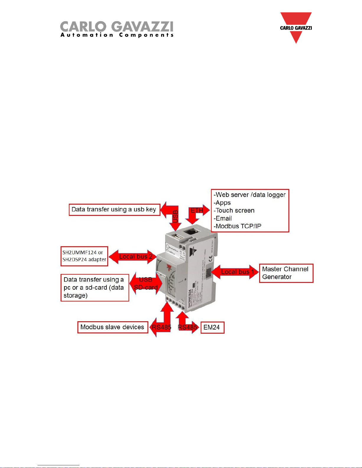
The system is based on a central CPU, the Sx2WEB24, a Linux based embedded PC that manages all
the smart functions. It is programmed by means of powerful software, the Sx tool. The Sx2WEB24 has
the Ethernet communication capability to be remotely controlled and monitored by smart-devices/PCs; it
is also a data logger that can record any value/event coming from the many buses it can connect to
(Wireless and Dupline® buses, two RS485 ports, Ethernet). This master unit is also provided with an
SD-card and USB port to upload/download data and system configurations.
The Sx2WEB24 is the brain of the system. It collects all the information from the buses it is connected
to. All the field devices such as light switches, input/output modules, sensors and so on are connected
to the Sx2WEB24 via the Dupline® bus. The Dupline® bus is not generated directly by the Sx2WEB24
but a bus generator is needed, the SH2MCG24.
Here below a diagram of the system is shown.
Page 6
How to install a Sx2WEB system
6
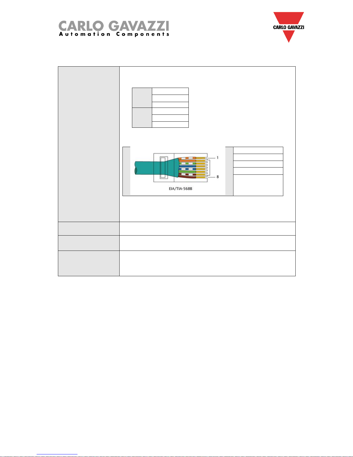
The following table provides a summary of the characteristics of the product:
Ports and connections
1 X 15 to 30Vdc power supply (A1+ and A2-)
2 X RS-485 (COM1 and COM2) :
COM1
Data – (A-)
Data + (B+)
GND
COM2
Data – (A-)
Data + (B+)
GND
1 X RJ-45 connector for 10/100 Base-T Ethernet [Communication]
Pin 1 TX+
Pin 2 TX-
Pin 3 Rx+
Pin 6 Rx-
1 X standard USB
1 X mini USB connection
1 X slot for micro SD or SDHC memory card
Absorption
5W Max.
Operating conditions
-25°C to 40°C
COM port termination
Both COM ports are internally terminated with a value of 150Ω and
polarized with two 511Ω resistors (from “B+” to +5V and from “A-“ to
GND). As a consequence no other external connection is required
from the SX2WEB24 side (see Appendix A for the other termination).
1.1.1 Sx2WEB24 bus description
Local bus 1: This is placed in the connector on the right side and it is called the High Speed bus. This
bus is used to connect the Dupline® generators to the Sx2WEB24.
Local bus 2: This is placed in the connector on the left side and it is a USB bus used to connect to the
universal mobile modem SH2UMMF14
(*)
and to the usb dongle connection module SH2DSP24.
(*)
The SH2UMMF124 is no longer available.
RS485 port 1: This is a serial port used to connect to other third party serial devices.
RS485 port 2: This is a serial port with modbus master capability used to connect to Carlo Gavazzi
energy meters.
USB port: This is placed on the top of the housing and it can be used to change the IP address.
SD-card: It can be only used to change the IP address.
Ethernet port: This is placed on the top of the housing and has to be used to connect to the Sx tool.
Page 7

How to install a Sx2WEB system
7
The buses can be summarized as shown below.
N.B.: All the connections described in the following paragraphs must be carried out without
power supply.
Page 8
How to install a Sx2WEB system
8
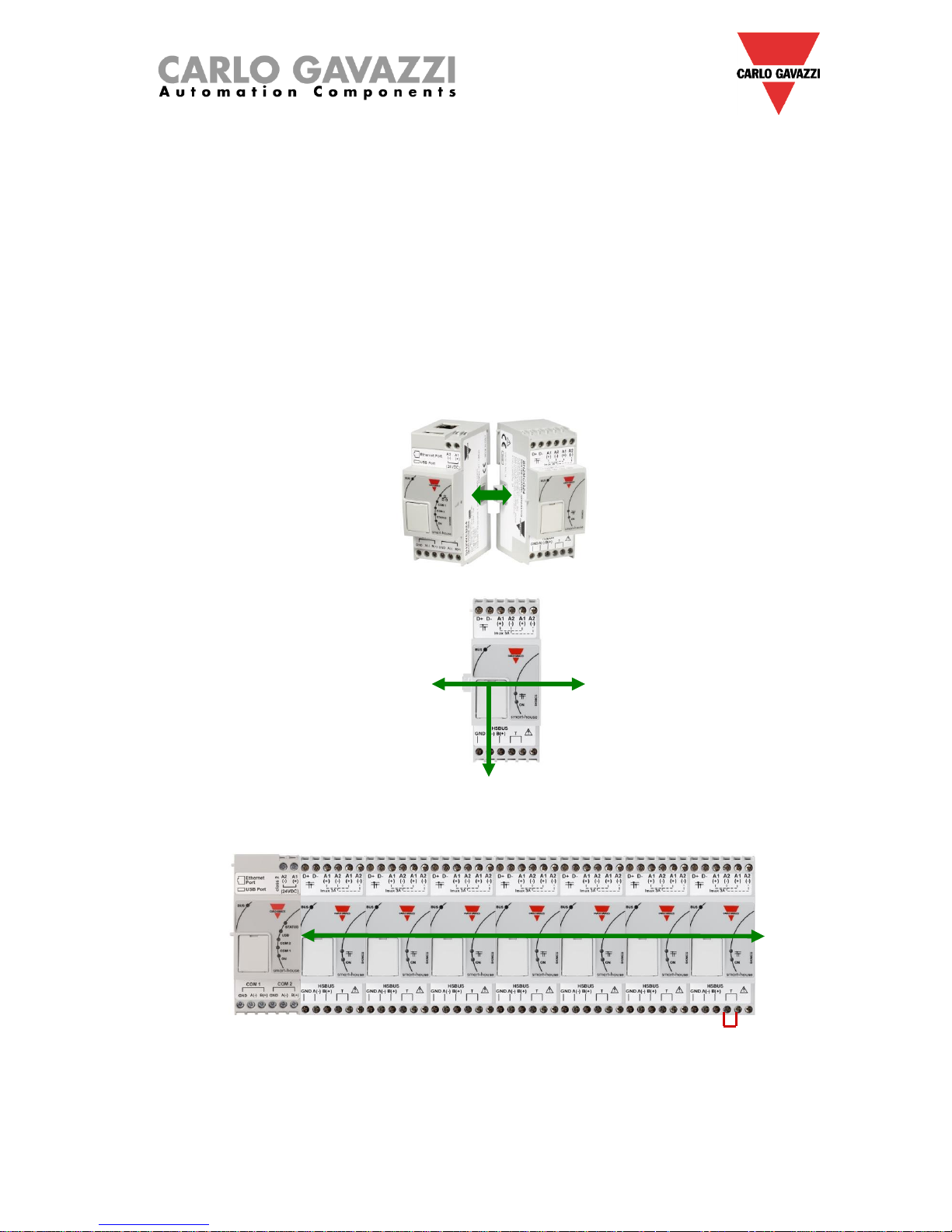
1.2 Bus generators
The Sx2WEB24 (i.e. SH2WEB24 or SB2WEB24) is the brain of the smart-house system but it cannot
work alone and it needs the Dupline® bus generators to send commands to the slave modules and
collect information from them. For this reason, the Dupline® bus generators can be considered as the
pulsating heart that makes all the information flow. They are connected to the Sx2WEB24 via the high
speed bus that is present both on the local bus and on the terminals at the bottom of the bus
generators. This means that the connection is very fast and easy in a cabinet, since the modules only
have to be plugged together, without any wiring, and at the same time it is very straightforward if the
bus generators have to be mounted in different cabinets. Up to 7 bus generators can be connected to
one Sx2WEB24.
The bus generators can be a mix of the Smart Dupline® generators SH2MCG24, the wireless bus
WiDup generators SH2WBU230N and the Dupline® generator SH2DUG24.
Example 1: The bus generators are all connected in the same Din-rail.
HSBUS
HSBUS
HSBUS
HSBUS
Page 9
How to install a Sx2WEB system
9
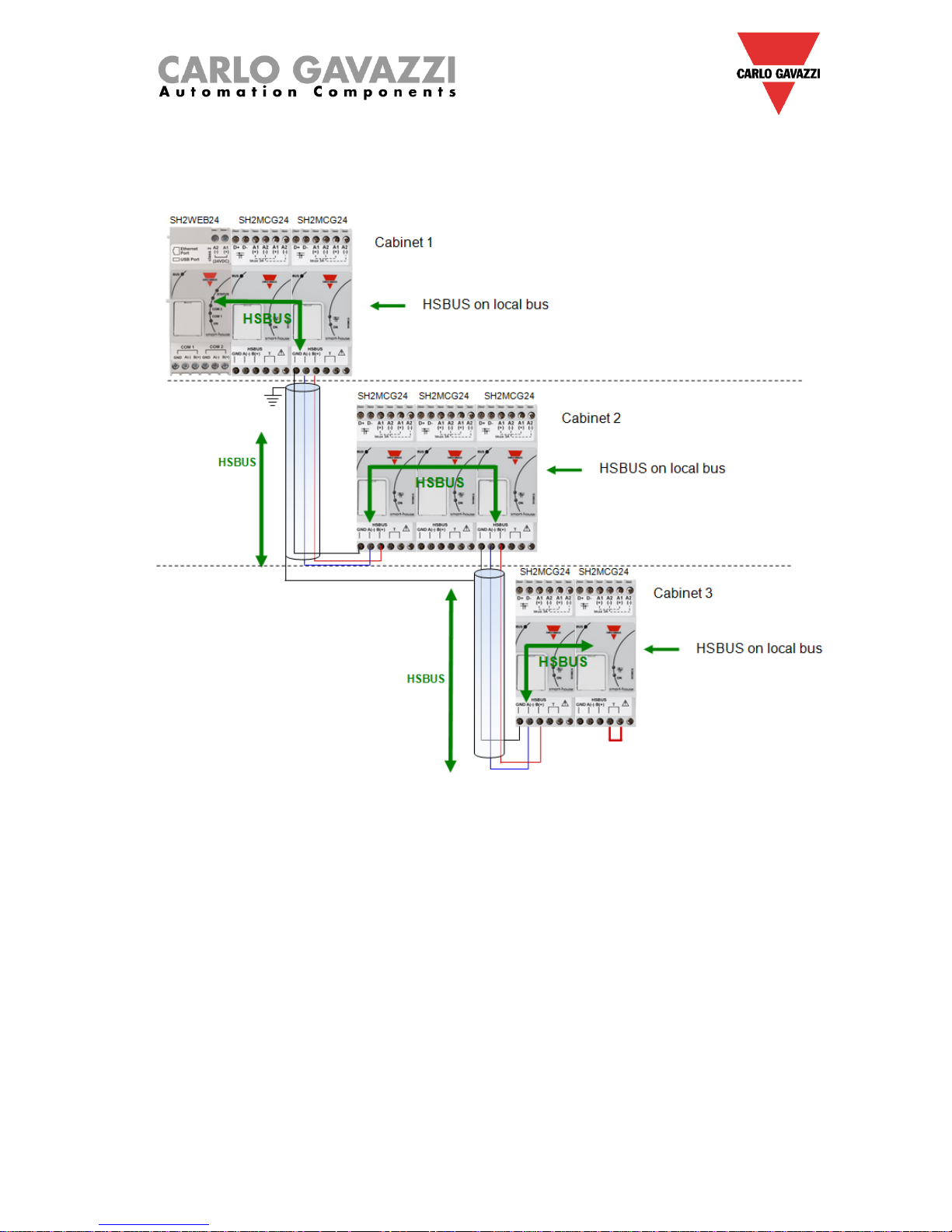
Example 2: The bus generators are mounted in different cabinets.
Page 10
How to install a Sx2WEB system
10
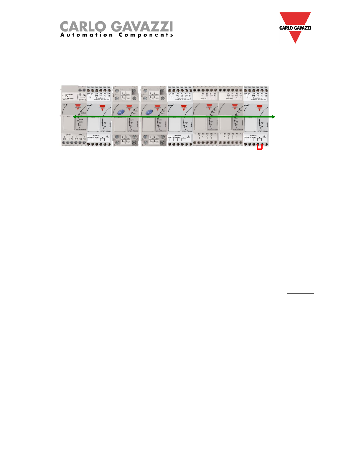
Example 3: The bus generators SH2MCG24 do not need to be put all together in a DIN rail, and they
can be mixed with the Dupline® modules as is shown in the picture below.
Sx2WEB24 SH2MCG24 SH2RE16A4 SH2RE16A4 SH2MCG24 SH2INDI424 SH2INDI424 SH2MCG24
Also in this case there is no need to wire the RS485 for the HS speed bus since the local bus connector
of the Dupline® modules is transparent to it. The installer only has to terminate the HS speed bus in the
last bus generator of the RS485 network.
1.2.1 Wiring the high speed bus
The high speed bus is an RS485 serial interface, at 256Kbit/s
The cable
The RS485 communication cable is a shielded, twisted pair cable. Many cable manufacturers supply
cable meeting the RS485 standard. Other cabling, such as telephone cable, coaxial cable and multicore wires should not be used as they could prove problematic and not provide satisfactory
performance.Cables must be at least 0.5 mm.
Topology
The cable must be installed to pass close by each node. Stubs (cables joining the node to the
cable),stars(multiple cable segments brought back to a single point) or loops must not be used.
Cable length
The maximum length of the cable is 600 metres.
Connection of the cable shield
The shield of the RS485 cable establishes a reference voltage for the RS485 signal conductors.
The "screen pig-tails" going into the terminals should be as short as possible. The shield should be
continuous throughout the installation, the best way is to connect the shield to earth ground in only one
point as nearest as possible to the SH2MCG24 (the best is on the terminal where the cable is
connected). This connection is not to be shared with other devices which could add external noise or
disturbance.
Termination
The network must be terminated at the end on the last bus generator of the network (see the T
terminals in the picture above) while it has already been terminated on the Sx2WEB24 side. This is to
avoid reflections which would disrupt communication.
Cable Insulation
The communication cable must not be run in cable trays carrying power wiring nor in close proximity to
power wiring. Current surges in power wiring due to high equipment starting currents or to faults can
disrupt communication.
For more details please see appendix A.
HSBUS
Page 11
How to install a Sx2WEB system
11
1.2.2 The Dupline® bus
The Dupline® bus is a signal transmission system that reduces the need for wires, as compared to an
ordinary installation. Using only 2 wires, the information can be transmitted from up to 2 km away. Many
input and output modules are supplied from the same 2 wires. Both digital (on-off) and analogue (e.g.
temperature, light level, wind speed and other) data is present on the bus at the same time and it is
collected by the SH2MCG24 and then processed by the Sx2WEB24.
The SH2MCG24 is the smart Dupline® bus generator that powers the Dupline® bus onto the local bus
and onto the terminals at the top. All the Dupline® slave modules have to be connected to one
SH2MCG24 to be part of the smart-house system.
The SH2MCG24 is powered by 15 to 30Vdc.
The Dupline® modules in the smart-house system can be divided into two groups:
- Decentralized modules: these are all the modules such as light switches, PIR sensors, lux
sensors, decentralized I/O modules, etc. which are mounted into the wall boxes or on the wall
- Centralized cabinet modules: these are the ones housed in the 1-DIN or 2-DIN housing for din
rail mounting
All our decentralised Dupline® devices are connected to each other with a single 2-wire cable. This
cable carries the communication signal that comes from the bus generator SH2MCG24. These 2 wires
carry a DC low-voltage pulsating signal, and therefore attention must be paid to keep the correct
polarity of the connection.
The Bus is overload and short-circuit protected, but anyway it is a good rule to avoid to invert
the polarity.
The modules cannot withstand voltages other than the Dupline® signal voltage (5.5V to 10V).
Dupline® bus
Dupline® bus
Page 12
How to install a Sx2WEB system
12
The so-called decentralised modules can be divided into the following groups:
- Light switches
- PIR sensors
- Temperature displays
- Water and smoke detectors
- Wind sensors
- Humidity sensors
- Light sensors
- Decentralised input/output modules
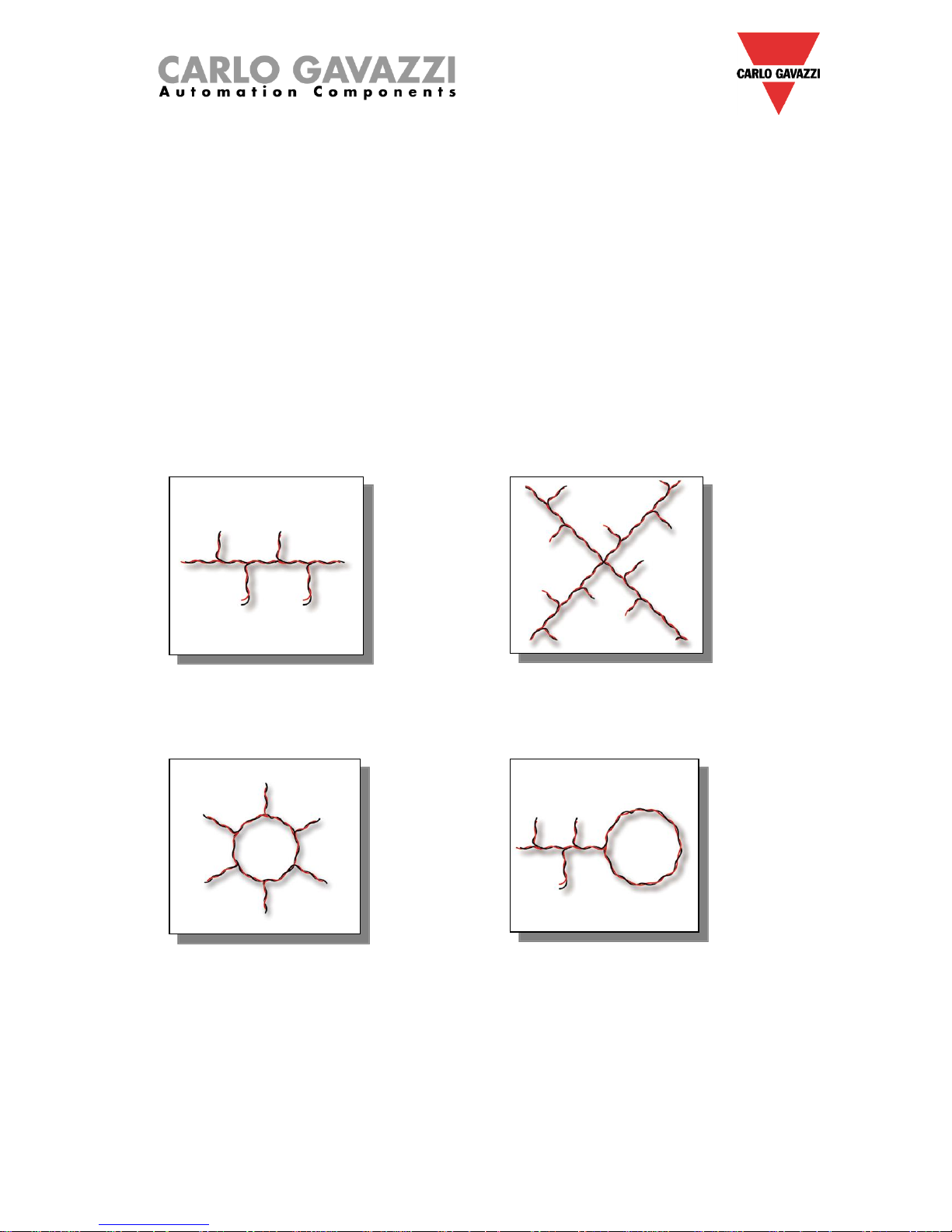
The installation is not to be engineered around the Dupline® bus because it can be matched to the
application. The routing of the cable may be in a line, star, ring or any combination.
Straight-through: the best
place for the SH2MCG24
would be in the middle of the
line
Star: the best place for the
SH2MCG24 would be in the
middle of the star
Ring: the best location for the
SH2MCG24 is in the middle
between the two farthest
distant modules.
Combined: the best location
for the SH2MCG24 is in the
middle between the two
farthest distant modules.
Page 13
How to install a Sx2WEB system
13
1.2.3 Cable and installation tips
1.2.3.1 New Installation Planning
When planning a new installation, a generic Bus cable can be used: it is better to use a twisted cable in
order to prevent electrical noise from affecting one conductor more than the other and thereby creating
an unbalanced Dupline® system.
In the case of very noisy installations (with noise sources such as contactors, inductive loads etc) we
recommend the use of a shielded cable.
The table below can be used to find the right cable: this can easily be carried out by considering the
maximum distance between the SH2MCG24 and the farthest module in the installation and checking
the table below.
The values shown in the table have been calculated considering a balanced distribution of the modules
in the Dupline® bus.
Installations where most of the modules are placed at the end of the network may be critical and this is
not recommended (the table is not valid in this case).
The values shown in the table are also suitable for installations where the majority of the modules are
placed at the beginning of the network (close to the SH2MCG24); this type of connection represents the
best configuration to guarantee the best performance of the system.
Table of cable sections:
Max current
Consumption
Cable size
0.75 mm2 (AWG 19), twisted
1 mm2 (AWG 17),
twisted
1.5 mm2 (AWG 15), twisted
450 mA
50 m
70 m
100 m
350 mA
65 m
90 m
130 m
300 mA
75 m
100 m
150 m
250 mA
90 m
120 m
180 m
200 mA
115 m
150 m
230 m
150 mA
150 m
200 m
300 m
100 mA
225 m
300 m
450 m
50 mA
450 m
600 m
900 m
The user is recommended to select cables according to the length and consumption shown in the table
above. It is also advisable to use polyethylene conductor insulation to have lower cable capacitance.
The total consumption of all the modules supplied by the Dupline® bus (e.g. light switch, PIR, lux
sensors) and the cable resistance affect the voltage of the Dupline® bus.
The drop in the Bus voltage might cause the modules placed far from the SH2MCG24 to not work
correctly.
Page 14

How to install a Sx2WEB system
14
1.2.3.2 Installation on Existing Cables
If the installation uses existing cables, it is important to verify the cross section of conductors according
to the above cable section table.
Once the cable size is checked, it is important to ensure that there is no leakage between the two
conductors and, also, no leakage from the conductors to ground or shield.
The best method of leakage testing before connecting any Dupline® modules is to use an insulation
tester (min. 500 V) to verify a resistance higher than 100.000 kΩ.
1.2.3.3 Cable Routing
The Dupline® cable is a signal cable and it should, therefore, be routed as such. This means that it is
better to keep it separate from power cables, high energy noise sources such as contactors, switched
inductive loads etc. However, if there are no other alternative possibilities, the routing of Dupline ®
cable may pass close to power cables. Should the power cables be very noisy, we suggest using
shielded cables.
1.2.3.4 Cable Splices and Connections
Cable splices are often the source of problems.
It is strongly recommended to splice only cables of the same characteristics (wire cross section,
capacitance, etc). The splicing contact resistance must be as low as possible. Twisted wire splicing
under a wire nut or terminal strip can deteriorate over a certain period of time. It is, therefore, advisable
to use soldering splices. For shielded cable the shield must be continued, but it must not be grounded
at the splicing points. Splices need to be water-tight to prevent the entry of water into the cable, which
could result in increased capacitance.
Note: Bad splices and/or splices left uncovered, exposed to humid environments, could create critical
problems difficult to route.
During the installation of each module, the length of external cables (input/output) must be selected
according to the datasheet reference.
These wires must be treated as signal wires and be kept away from contactors, relays, motors and
other inductive noise sources. In extreme cases it is necessary to use shielded cable. But here the
shield must also be properly grounded at one point only.
With the high flexibility of Dupline®, external input and output wires should, of course, be kept as short
as possible by bringing the Dupline® bus to the points where signals are to be transmitted or received.
Note: For the dimmer module the cable between the cabinet module and the light should not
exceed 25 metres.
Note: For input modules with contact inputs, the short circuit current (indicated on the individual
datasheets) must be noted and adequate switching devices must be selected for trouble-free operation.
Note: if multi-conductor cable is used, where some of the conductors are spare, we highly recommend
connecting all spare wires to ground (preferably close to the SH2MCG24). This to reduce the "antenna
effect" of open-end wires.
Recommendations:
1) Do not connect any of the wires to other voltage potentials.
2) Do not connect any of the wires to protective earth (PE).
3) Do not parallel any wires to increase the square of the cores.
4) Do not use cable gauges larger than 1.5 mm2 .
Page 15

How to install a Sx2WEB system
15
Connection examples:
Wrong connection:
This network design is not recommended because the cable resistance and the load from bus-powered
modules result in an excess of voltage drop.
Cabinet 2
Dupline modules
(e.g. 6 SH2RE16A4)
Cabinet 3
Dupline modules
(e.g. 6 SH2RE16A4
Main Cabinet
Sx2WEB24+SH2MCG24
150 m
Cabinet 4
Dupline modules
(e.g. 4 SH2RE16A4)
150 m
170 m
170 m
Cabinet 5
Dupline modules
(e.g. 6 SH2RE16A4)
Page 16

How to install a Sx2WEB system
16
Right connection:
Cabinet 2
Dupline modules
(e.g. 6 SH2RE16A4)
Cabinet 3
Dupline modules
(e.g. 6 SH2RE16A4
Main Cabinet
Sx2WEB24+SH2MCG24
150 m
Cabinet 4
SH2MCG24
+ Dupline modules
(e.g. 4 SH2RE16A4)
150 m
170 m
Cabinet 5
Dupline modules
(e.g. 6 SH2RE16A4)
RS485
HSBUS from
first SH2MCG24 to
second SH2MCG24
Network 1
Orange and green Cabinets
Network 2
Red and Violet Cabinets
500 m RS-485 cable
Page 17

How to install a Sx2WEB system
17
1.2.4 How to extend the Dupline ® bus
1.2.4.1 Network design
Sometimes, in new or in existing installations, there is the need to extend the length of the Dupline®
network beyond the typical Dupline® operative distance. At the same time, it could be necessary to
place some modules at the end of the Dupline® network where a balanced distribution of the modules
is not possible: the cable resistance and load from bus-powered modules result in an excess voltage
drop and might cause the modules placed far from the Dupline® generator not to work properly.
The SB2REP230 module is a 115 to 230 VAC-powered Dupline® repeater and isolator and is the ideal
solution to overcome the problems described above. It also allows the network design to be simplified
and it can be connected to any point on the Dupline® bus.
The picture below shows a simplified wiring diagram between the Dupline® repeater and the Dupline®
generator:
SH2MCG24 SB2REP230
PRIMARY DUPLINE® SIDE
SECONDARY DUPLINE® SIDE
MASTER SIDE NETWORK DISTANCE
EXTENDED SIDE NETWORK DISTANCE
TOTAL DISTANCE
Dupline®
modules
Dupline®
modules
Page 18

How to install a Sx2WEB system
18
1.2.4.2 Repeater wiring
The repeater regenerates the voltage level of the Dupline® signal from the bus generator and also
provides an output drive capability of up to 300mA. Since most of the Dupline slave modules are buspowered, the SB2REP230 provides the bus power supply to the modules connected to it.
Example 1:
Sx2WEB24 SH2MCG24 MODULE A MODULE B
SB2REP230
MODULE C MODULE D
Note: the local bus on both sides is connected to the primary side of the Dupline network, so the
secondary side has always to be connected to the terminals REP+ and REP-
Dupline current for Modules A and B are provided by the Dupline® generator
Dupline current for Modules C and D are provided by the Dupline® repeater
Page 19

How to install a Sx2WEB system
19
The Dupline® repeater does not create any new Dupline® network: all the Dupline® slave modules
connected to the SB2REP230 are part of the same network generated by the SH2MCG24 which the
repeater is connected to.
Example 2: The example below shows the network topology
SX2WEB24 SH2MCG24 SH2MCG24 SH2RE16A4 SH2RE16A4 SH2SSTRI424
SB2REP230
Modules D and E are part of the Dupline® network 1
Modules A, B and C are part of the Dupline® network 2
Network
1
Network
2
Module
A
Module
B
Module
C
Module
D
Module
E
Dupline® bus
(local bus: primary Dupline® side of Network 1)
Dupline® bus
(Rep+ Rep- : secondary Dupline® side of Network 1)
Page 20

How to install a Sx2WEB system
20
1.2.4.3 Isolator feature
In addition, the isolator feature contributes to the separation of the sides of the bus for maximum safety.
The primary and secondary Dupline® signals are isolated, which means the primary side, made up of
the modules connected to the Dupline® generator, will continue to operate in the case of a short circuit
on the secondary side, made up of the modules connected to the Dupline® repeater.
As shown in the example below, the modules connected to the Dupline generator (shown in the green
box) will continue to operate in the case of a short circuit on the secondary side (shown in the red box)
Example 3:
SH2MCG24 SB2REP230
As soon as the short circuit is removed, the secondary side will automatically become operational
again.
N.B. In the case of a short circuit on the primary Dupline® side, the secondary Dupline® also goes
down: until the short circuit is removed (see above), neither of the Dupline sides will operate.
1.2.4.4 Placing the SB2REP230 in a project
To wire a Dupline repeater into a network, the Dupline transparent module SH1DUPFT has to be used:
the terminals on the top of the SH2MCG24 are connected to the Transparent module and the Dupline
repeater just has to be plugged into the local bus connector. The Dupline® repeater is typically
mounted in a different cabinet some distance from the SH2MCG24.
The secondary side has to be connected to the terminals REP+ and REP- (see pictures on pages 18
and 19).
The Dupline repeater is able to regenerate the bus voltage starting from a minimum value of 5.5V: care
must be taken to connect it before the voltage drops to below this minimum voltage.
Recommendation:
On each bus branch it is not possible to connect more than one repeater in series: the connection
shown in the picture below must be avoided.
SH2MCG24 SB2REP230 SB2REP230 Dupline® modules
PRIMARY DUPLINE® SIDE
SECONDARY DUPLINE® SIDE
PRIMARY DUPLINE® SIDE
SECONDARY DUPLINE® SIDE
Dupline®
modules
Dupline®
modules
Page 21

How to install a Sx2WEB system
21
Example of correct wiring:
The example below shows a correct network design, where the installer has placed the Dupline® DINrail modules in different cabinets and the distances have been calculated by considering the cable
section and the voltage drop due to the bus-powered connected modules.
In the main cabinet, shown by the black square in the picture above, the installer has placed the
Sx2WEB24 and the SH2MCG24.
The other cabinets are shown in colours:
- the red one is 150 metres from the SH2MCG24: the repeater is not necessary because of the
short distance and the small load connected
- the yellow cabinet is next to the violet one and they are 170 metres away from the Dupline
generator. Here the installer has placed 6 Din-rail modules (SH2RE16A4), which do not
generate too high a voltage drop since, in normal conditions, the consumption of the 4 relay
modules supplied by the bus is 6mA ( even if this value increases when a relay is switched
on/off)
- in the violet cabinet, the installer has placed another 6 SH2RE16A4 modules
- the green cabinet is 700 metres away from the violet cabinet and the repeater is placed here to
boost the current and voltage, which otherwise are not sufficient to supply the other relay
modules placed here.
Example of Dupline Bus current calculation (see the voltage-drop file)
To calculate the voltage drop at the end of the 700m, as shown in the green cabinet in the picture above, the
installer has to use the excel file, available in our Product Selection website, in the SB2WEB24 and SH2WEB24
pages.
The data used to calculate the voltage drop in the example above is:
- Cable section: 0.75 mm;
- Number of modules in the yellow and violet cabinets: 12
- Consumption of a SH2RE16A4: 6mA
- Total consumption of the network: about 72 mA
- Voltage measured at the end of the 700m: 5.5V
Cabinet 2
Smart Dupline modules
(e.g. 6 SH2RE16A4)
Cabinet 3
Smart Dupline modules
(e.g. 6 SH2RE16A4
Cabinet 4
SB2REP230
Main Cabinet
Sx2WEB24+SH2MCG24
170 m
5 m
700 m
150 m
Cabinet 5
Smart Dupline modules
(e.g. 4 SH2RE16A4)
Page 22

How to install a Sx2WEB system
22
Page 23

How to install a Sx2WEB system
23
1.2.5 How to define the number of Dupline® networks
The smart-house system is based on a new protocol over the Dupline® bus that is called
SmartDupline®.
Smart Dupline® implements a master-slave protocol running over standard Dupline® networks.
The concept of SmartDupline® is based on the SIN: it is a Specific Identification Number that is unique
for each Dupline® module produced and it is written into the module during the production process and
cannot be modified.
The SIN code is printed on the product label by applying this format:
SIN: 255.255.255
It contains information about the type of the Dupline® module (light switches, pir, I/O modules, …), the
firmware release and much more.
SmartDupline® enriches the previous protocol with these features:
1) By means of the Specific Identification Number the Master can program the network address ADD
(1..250) in each device.
2) By means of the network address the Master can program the Dupline® standard channel
addresses and all the other module parameters.
3) By means of the network address the Master can access all input and output module information.
4) In a single message frame it is possible to manage double word information.
5) A CRC control is implemented in request and reply frames. Should an error occur, the bus
generator resends the request until it receives a correct frame.
Analogue data is transmitted via the SmartDupline® protocol without using digital I/O channels.
To calculate the number of SH2MCG24 required, the following points have to be taken into
consideration:
1) Each SH2MCG24 can drive up to 250 Dupline® modules (as explained above, it can assign
network addresses from 1 to 250).
2) Each SH2MCG24 can manage up to 112 output signals (e.g. output relays, LEDs, dimmer,…)
3) Each SH2MCG24 can manage up to 120 input signals (light switches, digital input,…)
4) Since most of the Dupline® slave modules are powered by the bus, the SH2MCG24 provides it
with a maximum output current of 450mA (at temperature 30°C), the lower is the current the
higher is the life time of all the system.
The installer will have to calculate the sum of the required modules and their consumption in terms of
current and input/output signals: when one of the four limits mentioned above is surpassed, a new
Dupline® network (i.e. a new SH2MCG24) has to be added.
We suggest designing the Dupline® networks in the best possible way by dividing them according to
specific areas (for example floors) and not to use the bus at its maximum load in order to have space
for further expansion and to prolong its life.
Page 24

How to install a Sx2WEB system
24
The consumption of input/output signals and current of every slave Dupline® module is given in the
relevant datasheet.
Current consumption: in the datasheet/instruction manual this is always given in the Dupline®
Specifications of each module.
Dupline® channel consumption: in the datasheet/instruction manual this is always given in the Mode of
Operation section under Coding/Addressing.
Page 25

How to install a Sx2WEB system
25
1.2.6 Dupline® bus in the cabinet
Thanks to the local bus concept, the DIN-rail slave modules (dimmers, relays, rollerblind modules,
etc…) can just be plugged into the SH2MCG24, without the need for any wiring. The
decentralised modules, such as light switches, PIR sensors, temperature display, …are connected to
the SH2MCG24 by the two wires coming from the terminals at the top.
If more bus generators are connected in a DIN rail, they do not need to be plugged next to one other
and they can also be mixed with the Dupline® I/O modules. The only rule that the installer has to take
into account is that a Dupline® I/O module is connected to the Dupline® network generated by the last
SH2MCG24 at its left. See picture below.
Example 1:
SX2WEB24 SH2MCG24 SH2MCG24 SH2RE16A4 SH2RE16A4 SH2SSTRI424
Modules A, B, and C are connected to the Dupline® network 2.
Dupline®
bus (local
bus)
Dupline® bus (wires)
Network
1
Network
2
Module
A
Module
B
Module
C
Page 26

How to install a Sx2WEB system
26
Example 2:
SX2WEB24 SH2MCG24 SH2RE16A4 SH2RE16A4 SH2MCG24 SH2SSTRI424 SH2MCG24 SH2SSTRI424
Modules A and B are connected to the Dupline® network 1.
Module C is connected to the Dupline® network 2.
Module D is connected to the Dupline® network 3.
Since there are no Dupline® terminals on the top of the slave modules, to connect the Dupline® bus
between different rails in a cabinet, the Dupline® transparent module SH1DUPFT has to be used.
The SH1DUPFT simplifies the wiring of a smart-house installation: it has to be connected at the
beginning of a rail row bringing the Dupline® bus from the top and bottom connectors to the internal bus
and vice versa. Internally, the three connectors are short-circuited. This means that the buses
connected to the top and bottom connectors must be in the same Dupline® network.
Network
1
Network
2
Network
3
Module
A
Module
B
Module
C
Module
D
Dupline® bus
Dupline® bus
Dupline® bus
Page 27

How to install a Sx2WEB system
27
Example 3:
Page 28

How to install a Sx2WEB system
28
Recommendations:
Do not connect one SH1DUPFT to two Dupline® networks, otherwise the two buses will be short-circuited: the
situation below must be avoided.
This connection must be avoided otherwise two Dupline® networks will be short circuited. If this
should happen, the system will not be damaged since the bus is protected, but it will not work
properly.
1.3 The wireless bus WiDup
Please see the manual How to install the smart-house wireless system.
Page 29

How to install a Sx2WEB system
29
1.4 How to connect the modem
The Universal Mobile Modem SH2UMMF124 or the USB Dongle Connection Module SH2DSP24 have
to be connected to the Sx2WEB24 through the auxiliary bus on the left side of the Sx2WEB24. The
modem can be used to send/receive messages or to access the Internet when the LAN connection is
not available.
The modem is configured by means of the Sx tool software: the user has to define the type of modem
used, the PPP parameters if necessary, the phone numbers from/to which it has to receive/send the
messages, the type of connection required (Data connection always active, Data connection if LAN not
available, Only LAN).
1.4.1 How to connect the USB Dongle Connection Module SH2DSP24
The SH2DSP24 is a Sx2WEB24 accessory module that provides a reliable and cost effective way to
connect to the Internet by using mobile networks via a dongle modem.
The installer has to carry out the following procedure:
1. Connect the SH2DSP24 to the left of the Sx2WEB24 controller;
2. Insert the SIM into the dongle USB modem
(*)
through the SIM slot. Make sure the SIM is not
protected by a PIN code (should that be the case, disable the protection). Please refer to the
user manual of the model/manufacturer;
3. Insert the USB modem into the USB port located on the top of the SH2DSP24 module;
4. Connect the 24VDC power supply;
5. Configure it by means of the Sx tool software.
SH2DSP24 SH2WEB24
USB Local bus
USB port
dedicated for
Dongle modem
Dongle modem
Page 30

How to install a Sx2WEB system
30
(*)
The table below shows the compatible USB modems:
Manufacturer
Model
Type
HUAWEI
MS2131
3G modem
D-LINK
DWM 157
Recommendation:
Place the modem where there is good signal reception: this can be checked by connecting to the Sx
tool: at the bottom of the user interface there are 5 bars that indicate the field strength, as shown in the
picture below.
N.B. Since the USB port used by the dongle modem is the same as the one used by the USB key
in the Sx2WEB24, the USB key cannot be used if the modem is already connected.
Page 31

How to install a Sx2WEB system
31
1.4.2 How to connect the Universal Mobile Modem SH2UMMF124
The Universal mobile modem SH2UMMF124 module is no longer available: it is mentioned here only to
understand compatibility with the past.
The installer has to perform the following steps to install the SH2UMMF124 modem:
1. Connect the SH2UMMF124 to the left of the Sx2WEB24 controller;
2. Insert the SIM into the SH2UMMF124 modem through the special slot. Make sure the SIM is
not protected by a PIN code (should that be the case, disable the protection);
3. Connect the antenna;
4. Connect the 24VDC power supply;
5. Configure it by means of the Sx tool software.
SH2UMMF124 SH2WEB24
Recommendation:
Place the modem where there is good signal reception: this can be checked by connecting to the Sx
tool: at the bottom of the user interface there are 5 bars that indicate the field strength, as shown in the
example in the picture below.
N.B. Since the USB port used by the dongle modem is the same as the one used by the USB key
in the Sx2WEB24, the USB key cannot be used if the modem is already connected.
USB Local bus
Page 32

How to install a Sx2WEB system
32
1.5 How to connect the energy meters
COM port 2 of the Sx2WEB24 is an RS-485 port with Modbus master capability. COM port 1 can be
configured as Modbus master or Modbus slave.
The Sx2WEB24 is a data logger that collects data from the energy meters.
Up to 128 energy meters can be connected to one Sx2WEB24:
Up to 64 can be connected to COM2 port;
Up to 64 can be connected to COM1 only if it is configured as Modbus master;
The data is saved in an .XLSX or .CSV file and can be downloaded by using the Sx tool or the
webserver of the Sx2WEB24, accessing it with a PC.
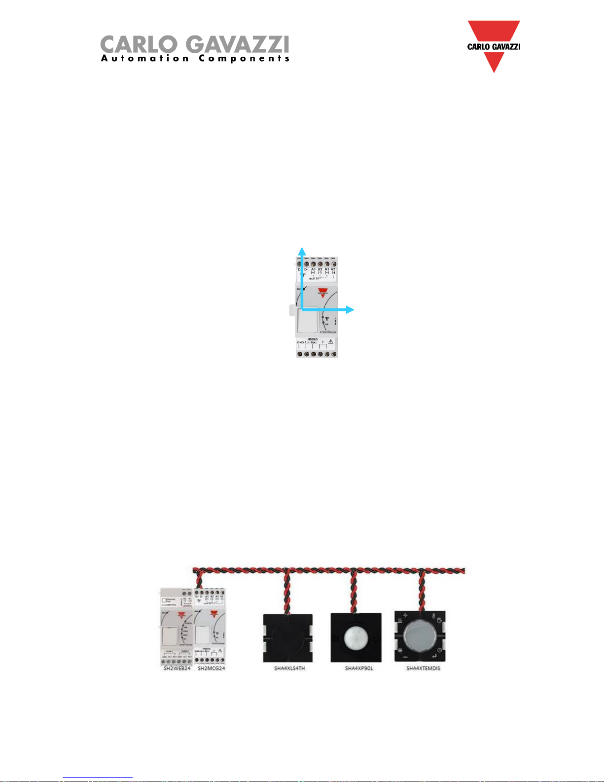
An example of the connection between an energy meter and the Sx2WEB24 is shown below:
Different types of energy meter can be mixed, and they can also have different baud rate (see the Sx
tool software manual for more details about how to configure the Sx2WEB24 to manage them).
N.B. The energy meters should be configured and connected to the load as described in the
relevant instruction manuals. No configuration nor discovery can be carried out using the Sx
tool software.
For more details about the wiring of the RS-485, please refer to appendix A.
Page 33

How to install a Sx2WEB system
33
1.6 Ethernet connection
The Sx2WEB24 is configured by using the Sx tool, which has to be connected via the LAN port on the
top of the Sx2WEB24.
When connecting the network cable, the Ethernet port LEDS will also light up.
To configure the IP address, please refer to the Sx tool software manual.
The LAN connection can be used to connect the Sx2WEB24 to an Ethernet network when it has to be
connected to other devices over TCP/IP such as the BTM-Tx-24 display.
The TCP/IP device can be connected
directly to the Sx2WEB24 with a peer to
peer connection by using fixed IP (see the
Sx tool manual to configure a fixed IP).
The TCP/IP devices can be connected
to the Sx2WEB24 via a router by using
both DHCP addressing or fixed IP with
NAT forwarding if the Sx2WEB24 is to
be visualised via the Internet.
Page 34

How to install a Sx2WEB system
34
1.7 Micro SD
The IP address can be changed by using a “Micro SD” or “SDHC” memory card correctly inserted into
the relevant slot (see Sx tool software manual).
N.B: the maximum capacity of the Micro SD card is 16GB.
1. Open the flap located on the Sx2WEB24 front panel. Identify the slot specifically designed for the
insertion of the “Micro SD” memory card.
2. Insert the Micro SD card, making sure it is not write-protected and it is correctly formatted (FAT32).
3. Close the flap. Warning: if the flap is not properly closed Sx2WEB24 will not enable any writing or
reading operation (flap closing is verified by a micro switch located under the flap).
4. As soon as the flap is closed, Sx2WEB24 will install the newly inserted memory card and update the
IP address. Warning: opening the flap during the writing stage will stop the data transfer process and
may potentially damage the Micro SD memory.
Page 35

How to install a Sx2WEB system
35
1.8 Pen drive installation
The IP address can be changed by using a Pen drive.
N.B: the maximum capacity of the Micro SD card is 16GB.
1. Identify the USB port specifically designed for the insertion of the “Pen Drive” memory.
2. Insert the Pen-drive, making sure it is not write-protected and it is correctly formatted (FAT32).
3. As soon as you have inserted the Pen-drive, Sx2WEB24 will install the newly inserted memory and
update the IP address. While the installation and writing operations are under way, the front “USB”
LED (blue) will blink. Warning: disconnecting the Pen-drive during the writing stage will stop the data
transfer process.
Page 36

How to install a Sx2WEB system
36
1.9 Sizing of Carlo Gavazzi DC power supply
The smart-house system is powered by 24 Vdc nominal (15-30 Vdc)
Since most of the Decentral Dupline® slave modules are powered by the bus, the sizing of the power
supply has to be based on the DIN-rail modules, and among these only the ones powered by 15 to 30
Vdc: the power dimmers and the relay output modules that switch 230 Ac load are powered by 230Vac.
In the table below, the list of devices is given, with the relevant power consumption that has to be
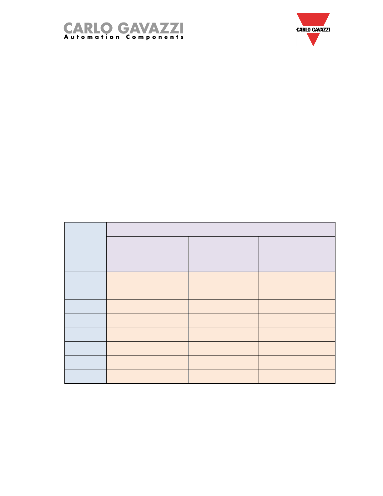
considered in the sizing of the power supply.
Item number
Description
Operational power
Sx2WEB24
Master unit
5.0 W
SH2MCG24
Bus generator
6.5 W
SH2RODC224
Roller blind module for DC motor
3.0 W
SH2ROAC224
Roller blind module for AC motor
3.0 W
SH2INDI424
Digital input module
0.4 W
SH2SSTRI424
Solid state relay output module
0.4W
SH2D10V424
1 to 10V dimmer
0.4 W
SH2UMMF124
Universal mobile modem
5.0 W
The suggested families are: SPDT24xx, SPM3241, SPM4241, SPM5 and SPM5B (battery charger).
According to the power required, the right models has to be selected.
1.9.1 How to calculate the power needed
To calculate the required power, the sum of the consumption of all the Din-rail modules has to be
calculated.
For example, if in an installation the following modules are present, the total consumption has to be
calculated following the column Consumption in the table below :
Item number
Quantity
Consumption
Sx2WEB24
1
1x 5.0 = 5.00 W
SH2MCG24
2
2x 6.5 = 13.0 W
SH2RODC224 0
SH2ROAC224
4
4x 3.0 = 12.0 W
SH2INDI424
2
2x 0.4 = 0.80 W
SH2SSTRI424 0
SH2D10V424
5
5x 0.4 = 2.00 W
SH2UMMF124
1
1x 5.0 = 5.00 W
Total needed
power
37.80 W
In this case a power supply delivering 40W is the right solution.
Page 37

How to install a Sx2WEB system
37
1.9.2 How to wire the power supply
The DIN-rail modules powered by to 24 Vdc nominal (15-30 Vdc) come with in/out connections to speed
up wiring: there are two A1(+) terminals that are internally short circuited, and two A2(-) terminals that
are also short circuited.
The best wiring should be carried out as shown below. The immunity to EMC can be improved
connecting the minus of the DC power supplier of the system (-) to the earth ground.
All the DIN-rail modules with the in/out terminals come with two short wires already screwed into the A1
and A2 terminals in order to speed up commissioning.
Recommendations:
1) Use a battery back-up system to avoid switching off the installation if a power down should
occur.
2) Be careful to have a total current not greater than 3A on the power supply if using the in/out
terminals, since the maximum current that the internal connections can withstand is 3A.
If Dc motors are used to control roller blinds or windows, do not supply them from the same
wires used in the in/out connections since the maximum current they can withstand is 3A (see
below: in this case the sizing of the power supply must take into consideration also the
consumption of the motor).
3) It is recommended that the system is supplied @24Vdc in order to reduce the current and thus
the stress on the internal electronic components. This will result in a longer lifetime of the
modules.
Page 38

How to install a Sx2WEB system
38
2 Installing the smart-house system
The installer has to perform the following steps to install a smart-house system:
1. Define the required smart-house functions and the relevant smart-house modules
2. Define the number of necessary bus generators, following the suggestion described in
paragraph How to define the number of Dupline® networks
3. Size the 24 Vdc power supply as described in paragraph Sizing of Carlo Gavazzi DC power
supply
4. Install the Dupline® bus, following the suggestion given in paragraph The Dupline® bus
5. Position and design the cabinet(s) correctly, following the suggestion given in the description of
the Dupline® bus and the HSbus.
6. If the modem is part of the installation, it has to be placed to the left of the SX2WEB24
7. The DIN-rail module has to be placed as described in the Dupline® a HSbus paragraphs
8. Connect the loads and inputs/outputs as described in the relevant datasheets of the DIN-rail
modules (ON/OFF light, dimmable light, blind motors, …)
9. If present, connect the energy meters to the serial port COM 2 and configure them (modbus
address, baud rate,…)
10. Connect the LAN if present via the Ethernet connector
11. Connect the power supply: 24Vdc and 230Vac
When switching on the Sx2WEB24, the following LEDs will light up on the front panel: green “ON” LED
(indicating the device is powered), yellow “BUS” LED (indicating HSbus activity), yellow COM2 LED
(indicating COM door activity), blue “USB” LED (indicating the presence of a USB device) and red
Status LED (at the first start-up it will be ON, indicating that no configuration is present or when it is
connected to a PC via the Sx tool). When connecting the network cable, the Ethernet port LEDS will
also light up.
When switching on the SH2MCG24, the following LEDs will light up on the front panel: green “ON” LED
(indicating the device is powered), yellow “BUS” LED (indicating HSbus activity), yellow Dupline® LED
(indicating Dupline® bus activity).
When switching on the SH2UMMF124, the following LEDs will light up on the front panel:
- Green LED: ON (indicating the machine is powered)
- Blue LED: fast blinking: searching for the cover signal / not registered / switching off.
slow blinking: service is registered and signal is available.
steadily on: communication under way.
When switching on the SH2DSP24, the green LED will be lit up, indicating the module is powered.
See the LED/LEDs on the dongle USB modem for any network information.
When switching ON the other DIN-rail I/O modules, the following LEDs will light up on the front panel:
green “ON” LED (indicating the device is powered), yellow “ON” Dupline® LED (indicating Dupline® bus
activity), red I/O LEDs (indicating the relevant input/output status).
After connecting and powering the Sx2WEB24, connect it to the Sx tool, following the instructions in the
Sx tool manual.
The Sx2WEB24 IP settings are factory-configured to start as DHCP. If no routers are present, please
change the IP address as described in the Sx tool manual, by using the USB key.
To create a configuration, please follow the instructions in the Sx tool manual.
Page 39

How to install a Sx2WEB system
39
3 Appendix “A” – RS485 network guidelines
3.1 MODBUS via Serial line (RS-485) guidelines
3.1.1 Introduction
The RS-485 is a half-duplex multidrop network: multiple transmitters and receivers may share the same
line, but only one transmitter may be active at any given time. The TIA/EIA-485-A says nothing about
the communication protocol to be used.
The MODBUS standard defines an application layer messaging protocol. The MODBUS Serial Line is a
master-slave protocol which may use the RS-485 as its physical interface.
3.1.2 RS-485 cable
The suggested cable is the shielded twisted for three wire connections. Cables must be at least
0,5mm2. The typical cable impedance should be between 100 ohm and 120 ohm.
3.1.3 RS-485 grounding
Communication through a RS-485 system is made by means of a balanced pair with a common so a
three wire connection is needed. The shield must be connected directly to earth ground, preferably at
one point only for the entire RS-485 Bus. Generally this point should be chosen on the master device or
on its tap and not shared with other devices (inverters,…) which could add external noise or
disturbance.
3.1.4 RS-485 shielding
A shielded cable is required to guarantee a high degree of immunity to EMC and lightning events.
The improvement of EMC immunity can also be done connecting the minus of the DC power supplier of
the system (-) to the earth ground.
3.1.5 RS-485 termination
A termination is needed at each end of the bus. Termination must not be placed anywhere else.
Suggested terminations are as follows:
Suggested terminations for MODBUS over RS485 serial line
Description
Type
Connection
Suggested termination
Notes
3W RS-485
Only on the
EM side
Between the two conductors of
the balanced line (near each end
of the bus)
R = 150 ohm/0.5W
(resistor)
EM24,
EM33
As for the SH2MCG24, EM21 and EM26 the relevant terminals have to be short circuited.
3.1.6 RS-485 wiring procedure
Suitable wire sleeves must be used for wiring. If any wire splice is to be used, this splice must be
soldered, taking special care to cover the splice with a cable shield and to ensure proper continuity.
Page 40

How to install a Sx2WEB system
40
3.1.7 RS-485 topology
Due to signal reflection issues, topology is not free, but only certain configurations are allowed. The only
configuration which guarantees sufficient reliability is the daisy-chain. The maximum length of a derivation is
1 metre.
Page 41

How to install a Sx2WEB system
41
4 Appendix B - Safety recommendations
This section contains important safety related information. If these recommendations are not strictly
followed, serious damage may occur to devices or machinery and serious injury or death may occur to
people. Please read this manual carefully before beginning any installation, maintenance or
operational activity.
Safety recommendations to be followed when installing, operating and maintaining the equipment.
SAFETY RECOMMENDATIONS
The manufacturer denies any kind of direct or
indirect responsibility for consequences resulting
from the non-observance of the safety
recommendations and from misuse of the
equipment.
UNAUTHORIZED PEOPLE
MUST NOT TOUCH
The product contains electrical components
constantly under voltage.
Only skilled personnel correctly trained to operate
on circuits constantly under voltage are allowed to
open the cover of the device.
DO NOT USE WATER TO
PUT OUT FIRE
Water jets or jets of other liquids must not come in
contact with the electric panel
INSTALL AVOIDING
DIRECT EXPOSURE
TO SUNLIGHT
Direct exposure to sunlight may cause overheating
even if the ambient temperature is in the requested
range. Do not install the device near to heat
sources.
DO NOT CONNECT
VOLTAGES EXCEEDING
RATED VALUES
Do not connect supply voltages exceeding rated
values to avoid damage to the equipment and
potential risk of injury or death to operators
DO NOT SHORT CIRCUIT
TERMINALS
Do not short circuit terminals (+) and (-) to avoid
damage to the equipment and injury or death to
operators
Page 42

How to install a Sx2WEB system
42
SAFETY RECOMMENDATIONS
The manufacturer denies any kind of direct or
indirect responsibility for consequences resulting
from the non-observance of the safety
recommendations and from misuse of the
equipment.
ELECTRICAL
COMPONENTS
CONSTANTLY UNDER
HIGH VOLTAGE
DANGER !!!
RISK OF DAMAGE AND
INJURY AS A RESULT OF
INCORRECT WIRING
Carefully check wiring. Incorrect wiring of the
device terminals can cause irreversible damage to
the equipment and injury to operators.
Use cable lugs for any wiring cables.
DANGER !!!
RISK OF DAMAGE AND
INJURY AS A RESULT OF
INCORRECT
GROUNDING
Carefully check grounding. The user must provide a
grounding system in compliance with the
regulations in force according to the electrical
installation in use.
DANGER !!!
FIRE HAZARD IN THE
PRESENCE OF
INFLAMMABLE FUMES
There is a fire or explosion hazard if the device is
installed in the presence of inflammable fumes.
The device must not be installed in places exposed
to explosion or fire hazard
ALWAYS TIGHTEN
SCREWS CORRECTLY
Always correctly tighten the fastening screws of the
wiring terminals
 Loading...