

Page 1
Specifications are subject to change (10.05.2002) 1
Type Rated operational Rated operational Control voltage
voltage U
e
current I
e
U
c
RSE: 22: 127/220 VAC, 50/60 Hz 25: 25 AAC 53b C:
Integral, 40: 230/400 VAC, 50/60 Hz 24 to 110 VAC/DC
motor controller 48: 277/480 VAC, 50/60 Hz & 110 to 480 VAC
60: 346/600 VAC, 50/60 Hz
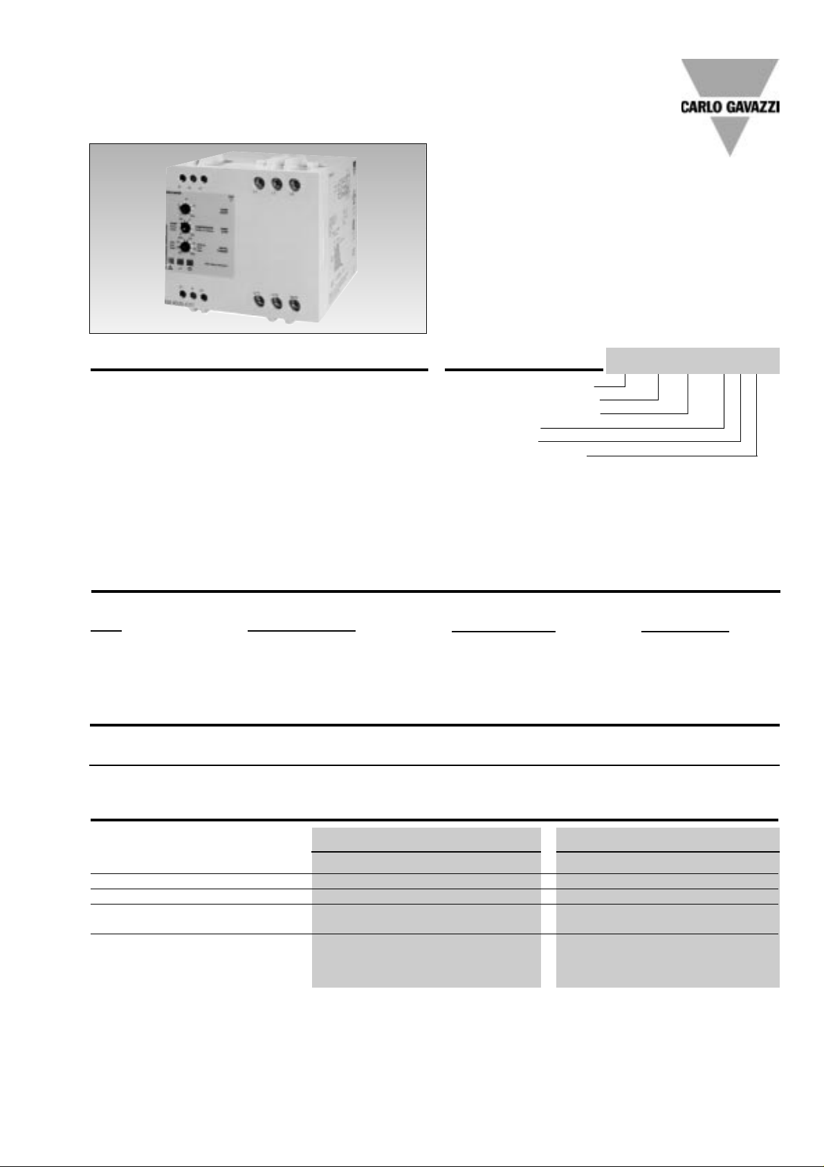
Integral Motor Controller
Rated operational voltage
Rated operational current
Control voltage
Ramp selector
Ramp version number
Ordering Key
Motor Controllers
AC Semiconductor Motor Controller
Type RSE..-CR1
• Soft starting and stopping of 3-phase
squirrel cage motors
• Ramp selector setting for
Pump or Compressor motors
• Initial Torque setting with kick-start option
• Rated operational current: 25 AAC 53 b
• Rated operational voltage: Up to 600 VAC, 50/60 Hz
• Potential-free control input
• LED- indications for power supply, ramping, bypassing
relays, phase sequence and overheating.
• Integral over-temperature protection
• Auxiliary relays for end of ramp, over-temperature
and phase sequence alarms
• Built-in transient over-voltage protection
Product Description
The RSE-CR1 is an AC semiconductor controller specifically designed to switch
pump and compressor
motors using start and stop
ramps matched to the application. Initial torque is user
adjustable with optional kickstart to allow matching of the
start conditions with the
motor load. The start ramp
can be adjusted to last up to
20 s. Two stop ramps can be
Type Selection
selected: pump or compressor. The pump setting produces an immediate drop in
load voltage down to the level
of the initial torque setting, followed by a gradual ramp
down lasting up to 20 s. The
compressor ramp down
option drops the voltage
immediately to zero, but this
drop can be delayed by maintaining full load voltage for up
to 20 s.
RSE 40 25 - C R 1
Rated operational current I
e
Motor Rating
5.5 kW/10 HP 11 kW/15 HP 15 kW/20 HP 18.5 kW/25 HP
25 AAC 53b RSE2225-CR1 RSE4025-CR1 RSE4825-CR1 RSE6025-CR1
Selection Guide
Control input specification
Control terminals A1 - A2 Control terminals A1 - A3
Control supply voltage Uc 24 - 110 VAC/DC ± 15% 110 - 480 VAC ± 15%
Control supply current approx. 12 mA approx. 5 mA
Rated frequency for AC 50-60 Hz ± 10% 50-60 Hz ± 10%
Rated insulation voltage 630 V rms 630 V rms
Overvoltage cat. III (IEC 60664) Overvoltage cat. III (IEC 60664)
Dielectric strength
Dielectric voltage 2 kVAC (rms) 2 kVAC (rms)
Rated impulse withstand volt. 4 kV (1.2/50 µs) 4 kV (1.2/50 µs)
Page 2
2 Specifications are subject to change (10.05.2002)
RSE..-CR1
Accuracy
Ramp up 20 ±10% on max.
≤ 0.5 s on min.
Ramp down 20 ±10% on max.
≤ 0.5 s on min.
Initial torque 50% ±5% on max.
< 5% on min.
Indication for
Power supply ON LED, green
Ramping LED, yellow (flashing)
Bypassing relays LED, yellow (constant ON)
Wrong phase sequence LED, red (flashing)
Overheated LED, red (constant ON)
Environment
Degree of protection IP 20
Pollution degree 3
Operating temperature -20°to +5 0 ° C ( - 4 °to +122°F)
Storage temperature
-50° to +85°C (-58° to +185°F)
Terminals Self lifting screw terminals
Control terminals nominal 2.5 mm
2
, AWG 14
Min. 0.5 mm
2
, AWG 20
Mounting torque max. 0.6 Nm
Power terminals nominal 10 mm
2
, or 2 x 6 mm
2
AWG 6 or 2 x AWG 10
Min. 1 mm
2
, AWG 16
Mounting torque max. 2.0 Nm
Approvals UL, CSA
CE-marking Yes
EMC Immunity EN 50 082-2
Electrostatic discharge (ESD) IEC 61000-4-2,
IEC 60947-4-2,
IEC 60801-2
Radio Frequency IEC 61000-4-3
Electromagnetic fields IEC 60947-4-2
ENV 50140
Radio Frequency IEC 61000-4-6
common mode IEC 60947-4-2
ENV 50141
Simulation of GSM signals
900 Mhz ENV 50204
Burst / Fast transients IEC 61000-4-4
Surge IEC 61000-4-5
Wire Conducted Emission EN 55011*
CISPR 11
IEC 60947-4-2
* For AC mains: 150kHz - 30MHz
Mode of Operation
General
This motor controller is intended
to softstart / stop 3-phase
squirrel cage induction motors,
especially in pump and compressor systems. Three useradjusted potentiometers are
provided to enable matching of
the ramp profiles to the specific
load. This device can also be
used in other applications with
similar load characteristics.
Starting
During motor starting this motor
controller can provide a gradual
ramp up with a maximum duration of 20 s; this is user adjusted
with the Ramp Start potentiometer. The Initial Torque
potentiometer can be adjusted
from 5 to 50% of maximum
torque (at full load voltage) to
match the load inertia. For
loads with high inertia, a kickstart can be user selected to
supply full voltage to the load
for 200 ms. After the kick-start
is performed, the voltage is
dropped according to the initial
torque % setting and ramp up
occurs. When the starting ramp
is completed, the bypass relays
and end of ramp relay (normally
open) are activated.
Stopping
This motor controller is
equipped with specific settings
for PUMP and COMPRESSOR
applications, although it can
also be utilised in other applications. The PUMP scale on the
Ramp Stop potentiometer
allows a ramp down with maximum duration of 20 ms (user
adjusted). At the beginning of
the downward ramp the full load
voltage is immediately reduced
to the level of the initial torque
setting to cause an immediate
deceleration of the PUMP system. The voltage is thereafter
reduced gradually to zero to
provide a smooth deceleration
and therefore minimise vibration
and potential leakage in the system under pressure. The COMPRESSOR setting provides an
immediate total reduction of
voltage to zero. This stopping
ramp can also be delayed by up
to 20 s to allow the system to
continue running until a new
control signal is applied. This
will help avoid unnecessary
stop-start sequences that can
damage the COMPRESSOR
system.
General Specifications
Alarm Relays
Over-temperature Alarm
- If over-temperature is detected
on the internal heatsink (>100ºC
approx.) when the motor controller is not ramping, the device
will not start, ramp up will not
occur and the alarm relay
(Normally Closed) contact will
open.
- When the temperature drops
below the critical level, reset will
only take place if the supply is
interrupted and re-applied.
- If over-temperature is detected
on the internal heatsink (>100ºC
approx.) when the bypass relays
are activated, the alarm relay
(Normally Closed) contact will
open to indicate fault.
Wrong phase sequence alarm
- At connection of power the
motor controller will start normally
- The alarm relay (Normally
Closed) contact opens
Supply Specifications
Overvoltage cat.III IEC (60664) 220 V 400 V 480 V 600 V
Operating supply voltage Uc 127/220 VACrms 230/400 VACrms 277/480 VACrms 346/600 VACrms
through L1, L2, L3 ± 15% ± 15% ± 15% ± 15%
Rated frequency 50-60 Hz ± 10% 50-60 Hz ± 10% 50-60 Hz ± 10% 50-60 Hz ± 10%
Output Specifications
Utilization category AC-53b Integral bypassing
of semiconductors
Overload current profile
(overload relay trip class) 25 A:AC-53b: 4-3: 120
Page 3

Specifications are subject to change (10.05.2002) 3
Operation Diagrams
Ramp Adjustments
Mains
Overheated
LED, green
RSE..-CR1
Sequence L1-L2-L3
Control input Uc
LED, yellow
LED, red
M
3~
Alarm reset
End of ramp
Pump without kickstart Pump with kickstart Compressor without kickstart Compressor with kickstart
with delay on release and delay on release
Housing material PC/ABS Blend
Colour Light grey
Terminal block PBTP
Colour Black
Bottom clips POM
Colour Black
Front knob PC
Colour Grey
Housing Specifications
Dimensions
All dimensions in mm
Functional Diagram
Rated opera- I2t for fusing I
TSM
dI/dt
tional current t = 1 - 10 ms
25 A 1250 A2s 500 Ap 100 A/µs
Semiconductor Data
Page 4

4 Specifications are subject to change (10.05.2002)
RSE..-CR1
Fusing Considerations
The motor controller provides
by-passing of the semiconductors during running operation. Therefore the semiconductors can only be damaged
by short-circuit currents during ramp-up and ramp-down
function.
Recommended fusing
Ferraz 6.900 CP gRC 14.5140
A 3-phase induction motor
with correctly installed and
adjusted overload protection
does not short totally between
lines or directly to earth as
some other types of loads, eg
heater bands. In a failing motor there will always be some
part of a winding to limit the
fault current. If the motor is
installed in an environment
where the supply to the motor
cannot be damaged, the short
circuit protection can be considered to be acceptable if the
controller is protected by a 3pole thermal-magnetic overload relay .
Applications
Changing from Direct ON
Line start to soft start
(Line controlled soft-start)
(Fig. 1)
Changing a Direct On Line start
into a soft start is very simple
with the RSE soft-starting relay:
1) Cut the cable to the motor
and insert the RSE relay .
2) Connect control input to two
of the incoming lines.
Set
initial torque to minimum
and
ramp up and down to maximum.
3) Power up again - adjust the
start torque so the motor
starts turning immediately
after power is applied, and
adjust ramp time to the
appropriate value.
When C1 is operated, the
motor controller will perform
soft-start of the motor. When
C1 is switched off, the motor
will stop, the motor controller
will reset and after 0.5 s a new
soft-start can be performed.
Please note that the controller
does not insulate the motor
from the mains. Contactor C1
is therefore needed as a service switch for the motor .
Fig. 1
1L1 3L2 5L3
L1 L2 L3
A1
A2
A3
U/T1 U/T2 W/T3
M
Fig. 2
S1
I > I >
I >
~
L1 L2 L3L1 L2 L3
C1 C1
L1 L2 L3
L1 L2 L3
M
M
U/T1 U/T2 W/T3
U/T1 U/T2 W/T3
A1
A2
A3
Soft-start and soft-stop
(Fig. 2)
When S1 is closed, soft-start
of the motor will be performed
according to the setting of the
ramp-up potentiometer and
the setting of the initial torque
potentiometer. When S1 is
opened, soft-stop will be performed according to the setting of the ramp-down
potentiometer .
Motor full load current (AACrms) 12-16 16-20 20-25
Overload relay type :GV 2- M 16 M 20 M 22
Manufacturer : Telemecanique M 20 M 21
Overload relay type: MS 325- 12.5 20 25
Manufacturer : ABB 16
Motor protection circuit breaker type KTA3-25- 16 20 25
Manufacturer : Allan Bradley/Sprecher + Schuh
Motor controller type :
127/220 V mains RSE 22 25 - CR1
230/400 V mains RSE 40 25 - CR1
277/488 V mains RSE 48 25 - CR1
347/600 V mains RSE 60 25 - CR1
Recommended thermal-magnetic overload relay
Selection Chart
Thermal-magnetic overload relay and motor controller
 Loading...