

Page 1

Solid State Relays
Industrial, 1-Phase ZS w. LED
Types RS 23 A, RS 40 A
• Zero switching AC Solid State Relay
• Direct copper bonding (DCB) technology
• LED indication
• Clip-on IP 20 protection cover
• Self-lifting terminals
• Housing free of moulding mass
• Fixed AC control input
• Operational ratings up to 40 AACrms and 400 VAC
• Blocking voltage: Up to 850 V
• Opto-isolation: > 4000 VACrms
p
Product De scrip tion
The zero switching relay is an
inexpensive solution for
resistive loads. The zero
switching relay switches ON
when the sinusoidal curve
crosses zero and switches
OFF when the current crosses zero. The LED indicates
the status of the control
input. The clip-on cover is
securing touch protection (IP
20). Output terminals can
handle cables up to 16 mm
Ordering Key
Solid State Relay
Number of poles
Switching mode
Rated operational voltage
2
Control voltage
.
Rated operational current
RS 1 A 23 A2- 25
Type Selection
Switching mode Rated operational Rated operational Control voltage
voltage current
A: Zero Switching 23: 230 VACrms 25: 25 AACrms A1: 110VAC ± 15%
40: 400 VACrms 40: 40 AACrms A2: 230VAC ± 15%
A4: 400VAC ± 15%
Selection Guide
Rated opera- Blocking Control Rated op er a tion al current
tional voltage voltage voltage 25 A 40 A
230 VACrms 650V
230 VAC ± 15% RS1A23A2-25 RS1A23A2-40
400 VAC ± 15% RS1A23A4-25 RS1A23A4-40
400 VACrms 850V
400 VAC ± 15% RS1A40A4-25 RS1A40A4-40
110 VAC ± 15% RS1A23A1-25 RS1A23A1-40
p
230 VAC ± 15% RS1A40A2-25 RS1A40A2-40
p
General Spec i fi ca tions
RS1A23... RS1A40...
Operational voltage range 42 to 265 VACrms 42 to 440 VACrms
Blocking voltage 650 V
Zero voltage turn-on 15 V 15 V
Operational frequency range 45 to 65 Hz 45 to 65 Hz
Power factor 0.95 @ 230 VACrms 0.95 @ 400 VACrms
Approvals UR, cUR, CSA, EAC UR, cUR, CSA, EAC
CE-marking Yes Yes
Specifications are subject to change without notice (30.10.2017 ) 1
p
850 V
p
Page 2
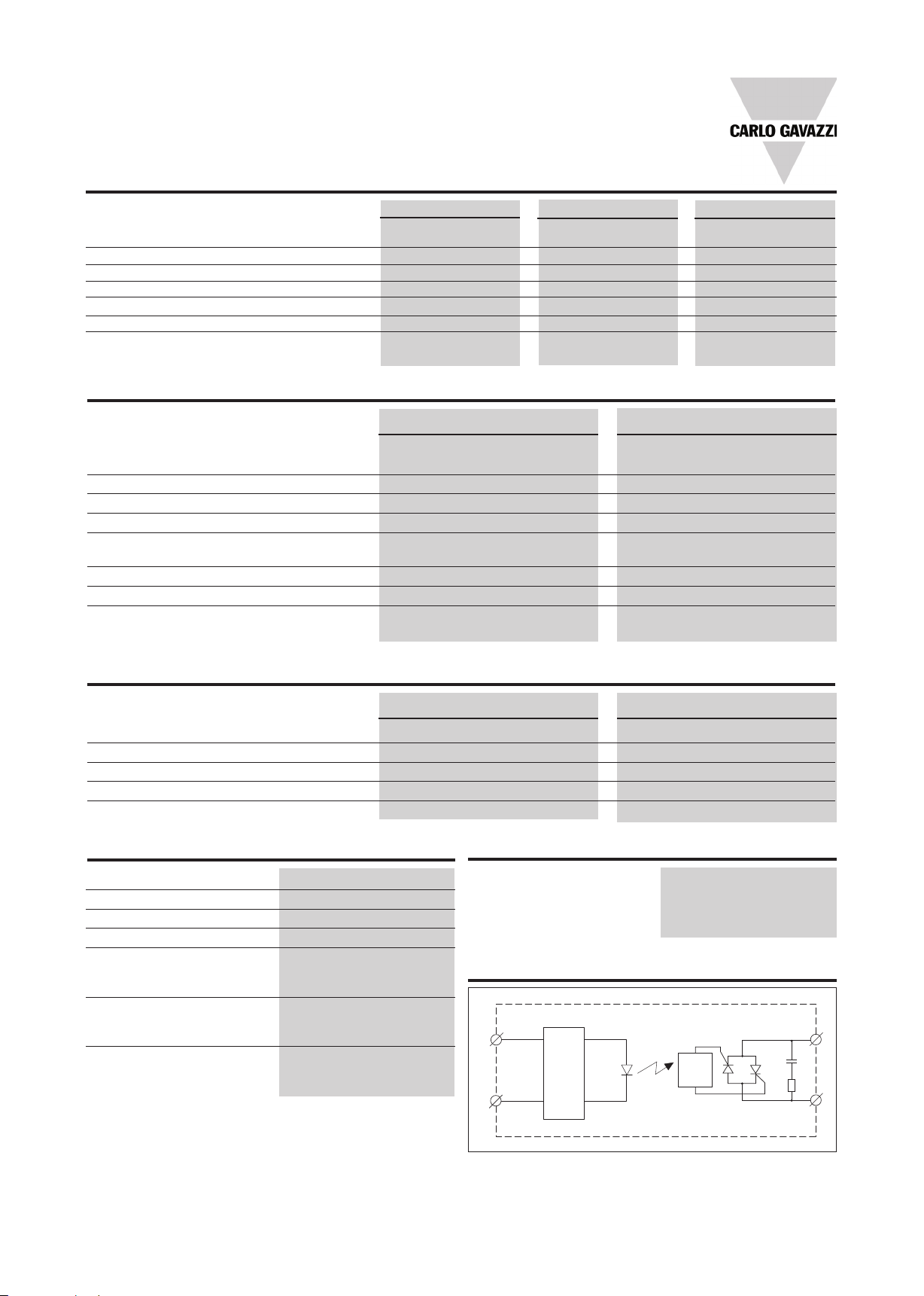
RS1A..A
1(~)
2(~)
3
4
REGULATION
ZC
Input Specifications
RS1A..A1 RS1A..A2 RS1A..A4
Control voltage 80 to 130VAC 200 to 260 VAC 360 to 440 VAC
Control frequency 50Hz / 60Hz 50Hz / 60Hz 50Hz / 60Hz
Pick-up voltage 70VAC 190VAC 350VAC
Drop out voltage 10VAC 20VAC 40VAC
Input current @ max input voltage 13mA 13mA 13mA
Typical response time pick-up 20ms 20ms 20ms
Typical response time drop-out 20ms 20ms 20ms
Output Specifications
RS1A...25 RS1A...40
Rated operational current
AC51 @ Ta=25°C 25 Arms 40 Arms
Min. operational current 150 mA 250 mA
Rep. overload current t=1 s < 55 AACrms < 125 AACrms
Non-rep. surge current t=10 ms 325 A
Off-state leakage current @ rated
voltage and frequency < 3 mArms < 3 mArms
I2t for fusing t=10 ms 525 A2s 1800 A2s
On-state voltage drop @ rated current 1.6 Vrms 1.6 Vrms
Critical dV/dt off-state 500 V/µs 500 V/µs
p
600 A
p
Thermal Specifications
RS1A...25 RS1A...40
Operating temperature -30° to 70°C -30° to 70°C
Storage temperature -40° to 100°C -40° to 100°C
Junction temperature 125°C 125°C
Rthjunction to case 0.8 oC/W 0.5 oC/W
junction to ambient 20 oC/W 20 oC/W
R
th
Housing Specifications
Weight Approx. 60 g
Housing material Noryl GFN 1, black
Baseplate Aluminium
Potting compound None
Relay
Mounting screws M5
Mounting torque 1.5-2.0 Nm
Control terminal
Mounting screws M3 x 9
Mounting torque 0.5 Nm
Power terminal
Mounting screws M5 x 9
Mounting torque 2.4 Nm
Isolation
Rated isolation voltage
Input to output 4000 VACrms
Output to case 4000 VACrms
Functional Diagram
2 Specifications are subject to change without notice (30.10.2017)
Page 3

RS1A..A
Heatsink Dimensions (load current versus ambient temperature)
RS..25
Load
current [A]
25.0
2.70 2.34 1.98 1.61 1.25 0.89
22.5
3.10 2.69 2.28 1.86 1.45 1.04
20.0
3.61 3.13 2.65 2.18 1.70 1.23
17.5
4.26 3.70 3.14 2.59 2.03 1.47
15.0
5.14 4.47 3.80 3.14 2.47 1.80
12.5
6.38 5.56 4.73 3.91 3.09 2.27
10.0
8.25 7.19 6.14 5.08 4.02 2.97
11.4 9.94 8.49 7.04 5.59 4.14
7.5
17.7 15.4 13.2 11.0 8.74 6.51
5.0
- - - - 18.2 13.6
2.5
20 30 40 50 60 70
Junction to ambient thermal resistance, R
Junction to case thermal resistance, R
Case to heatsink thermal resistance, R
hermal resistance
T
o
/W]
C
[
th j-a
th j-c
th c-s
Power
dissipation [W]
Ambient temp. [oC]
< 20.0 oC/W
< 1.10oC/W
< 0.20oC/W
Maximum allowable case temperature 100
Maximum allowable junction temperature 125
28
24
21
18
15
12
RS..40
Load
current [A]
40.0
1.54 1.32 1.10 0.89 0.67 0.45
36.0
1.78 1.53 1.28 1.04 0.79 0.54
32.0
2.08 1.79 1.51 1.22 0.94 0.65
28.0
2.47 2.14 1.80 1.47 1.13 0.80
24.0
2.99 2.59 2.19 1.80 1.40 1.00
20.0
3.73 3.24 2.75 2.26 1.77 1.27
16.0
9
7
4
2
T
A
4.84 4.21 3.58 2.95 2.32 1.69
6.71 5.85 4.98 4.12 3.25 2.39
12.0
10.46 9.12 7.79 6.46 5.13 3.80
8.0
---- ---- 16.2 13.5 10.8 8.0
4.0
20 30 40 50 60 70
Junction to ambient thermal resistance, R
Junction to case thermal resistance, R
Case to heatsink thermal resistance, R
o
C
o
C
Maximum allowable case temperature 100
Maximum allowable junction temperature 125
hermal resistance
T
o
/W]
C
[
ower
P
issipation [W]
d
Ambient temp. [oC]
th j-a
th j-c
th c-s
46
40
35
30
25
20
16
12
8
4
T
A
< 20.0 oC/W
< 0.80oC/W
< 0.20oC/W
o
C
o
C
Heatsink Selection
Carlo Gavazzi Heatsink Thermal ...for power
(see Accessories) resistance... dissipation
No heatsink required --- N/A
RHS 300 5.00 K/W > 0 W
RHS 100 3.00 K/W > 25 W
RHS 45C 2.70 K/W > 60 W
RHS 45B 2.00 K/W > 60 W
RHS 90A 1.35 K/W > 60 W
RHS 45C plus fan 1.25 K/W > 0 W
RHS 45B plus fan 1.20 K/W > 0 W
RHS 112A 1.10 K/W > 100 W
RHS 301 0.80 K/W > 70 W
RHS 90A plus fan 0.45 K/W > 0 W
RHS 112A plus fan 0.40 K/W > 0 W
RHS 301 plus fan 0.25 K/W > 0 W
Consult your distribution > 0.25 K/W N/A
Infinite heatsink - No solution
--- N/A
Dimensions
All dimensions in mm
Specifications are subject to change without notice (30.10.2017 ) 3
Page 4

25
The declaration in this section is prepared in compliance with People’s Republic of China Electronic Industry Standard SJ/
T11364-2014: Marking for the Restricted Use of Hazardous Substances in Electronic and Electrical Products.
Part Name Toxic or Harardous Substances and Elements
Lead
(Pb)
Mercury
(Hg)
Cadmium
(Cd)
Hexavalent
Chromium
(Cr(Vl))
Polybrominated
biphenyls (PBB)
Polybrominated
diphenyl ethers
(PBDE)
Power Unit Assembly x O O O O O
O: Indicates that said hazardous substance contained in homogeneous materials fot this part are below the limit requirement of GB/T 26572.
X: Indicates that said hazardous substance contained in one of the homogeneous materials used for this part is above the
limit requirement of GB/T 26572.
E
䉭❁䄷⻥
忀Ụ䔚㗵㠠㍕Ḕ⌵ạ㯸⅘⑳⛤䔜⬷ⷌḁ㟮↭
6-7Ɲ㟮㳏✏䔜⬷䔜㯻Ẏ⒨Ḕ昷⮁ὦ䔏䙫㛰⮚䉐崏
杇䩁 㝚㰣㉧㝚Ⰴ䊺嵹ṟ↔䵱
攖
(Pb)
㲯
(Hg)
斚
(Cd)
↾Ὀ攽
(Cr(Vl))
⥫㼅⍧傥區
(PBB)
⥫㼅傥區懫
(PBDE)
⋰䏘⎦↔ xO O O O O
2㮵杇㊑㝚㞡㗪Ṿ⑼㝚䛕尶㝚Ⰴ䊺ᾟở*%7䛕暡⯫˛
;㮵杇㠡䨞㞡㗪Ṿ⑼㝚䛕尶㝚Ⰴ䊺欩ở*%7䛕暡⯫˛
RS1A..A
Environmental Information
4 Specifications are subject to change without notice (30.10.2017)
Page 5

RS1A..A
Faston terminals
Other Accessories
• Fast-on tabs
• Tab dimensions
according to DIN 46342
part 1
• Pure tin-plated brass
• Heatsinks and fans
• Type RHS....
• 0.25 to 5.00 k/W
• Single and dual
relay types
Ordering Key
Screw mounted
Faston terminals
RS, RM Solid State Relay
Faston terminals
Tab orientation
nput Tab width: 4.8mm
I
utput Tab width: 6.3mm
O
Faston terminals
in packs of 20
RS, RM Solid State Relay
Tab orientation
*
0: Flat (0º)
4: Angled (45º)
** 48: 4.8mm faston for input
RS1A23A2-25 F 4
RM48 F4
63: 6.3mm faston for output
• Touch safety cover
• Type RMIP20
• IP20 protection degree
• Pack size: 20 pieces
**
*
*
All accessories can be ordered pre-assembled with Solid State Relays.
Other accessories include DIN rail adaptors, fuses, varistors and spacers.
For futher information refer to Accessories datasheets.
Specifications are subject to change without notice (30.10.2017) 5
 Loading...