

Page 1
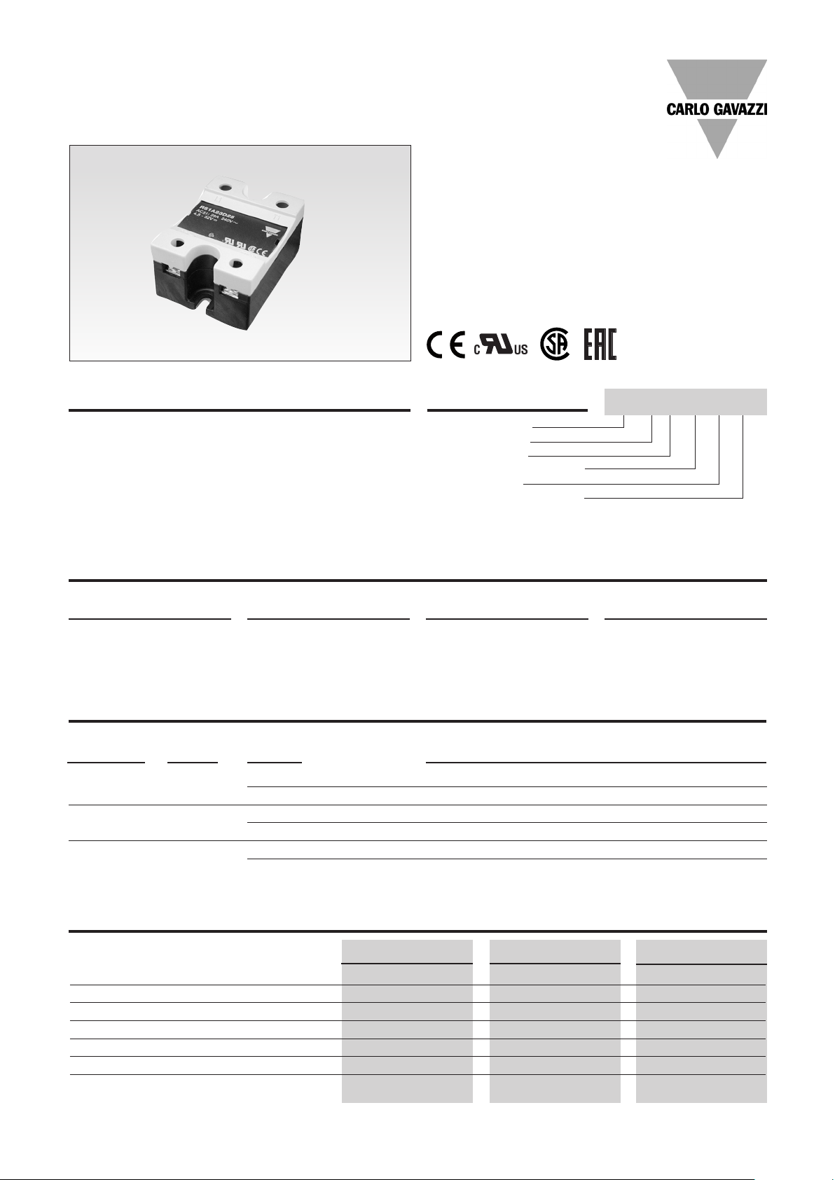
Solid State Relays
Industrial, 1-Phase ZS w. LED
Types RS 23, RS 40, RS 48
• Zero switching AC Solid State Relay
• Direct copper bonding (DCB) technology
in 25A and 40A types
• LED indication
• Clip-on IP 20 protection cover
• Self-lifting terminals
• Housing free of moulding mass
• 2 input ranges: 4-32 VDC and 18-36 VAC/VDC
• Operational ratings up to 40 AACrms and 480 VAC
• Blocking voltage: Up to 1200 V
• Opto-isolation: > 4000 VACrms
• Integrated snubber network in 25 A and 40 A types
p
Product De scrip tion
The zero switching relay with
triac (10 A) or thyristor output
(25 A, 40 A) offer a solution
for resistive load switching.
The zero switching relay
switches ON when the sinusoidal voltage crosses zero
and switches OFF when the
current crosses zero. The
LED indicates the status of
the control input. The clip-on
cover is securing touch protection to IP 20. Output terminals can handle cables up
to 16 mm2.
Ordering Key
Solid State Relay
Number of poles
Switching mode
Rated operational voltage
Control voltage
Rated operational current
RS 1 A 23 D 25
Type Selection
Switching mode Rated operational Rated operational Control voltage
voltage current
A: Zero Switching 23: 230 VACrms 10: 10 AACrms LA: 18 to 36 VAC/VDC
40: 400 VACrms 25: 25 AACrms D: 3 to 32 VDC*
48: 480 VACrms 40: 40 AACrms *4 to 32 VDC for 400 VAC
and 480VAC types
Selection Guide
Rated opera- Non-rep. Control Rated op er a tion al current
tional voltage voltage voltage 10 A 25 A 40 A
230 VACrms 650 Vp 3-32 VDC RS1A23D10 RS1A23D25 RS1A23D40
18-36 VAC/DC RS1A23LA10 RS1A23LA25 RS1A23LA40
400 VACrms 850 Vp 4-32 VDC RS1A40D10 RS1A40D25 RS1A40D40
18-36 VAC/DC RS1A40LA10 RS1A40LA25 RS1A40LA40
480 VACrms 1200 Vp 4-32 VDC RS1A48D10 RS1A48D25 RS1A48D40
18-36 VAC/DC RS1A48LA10 RS1A48LA25 RS1A48LA40
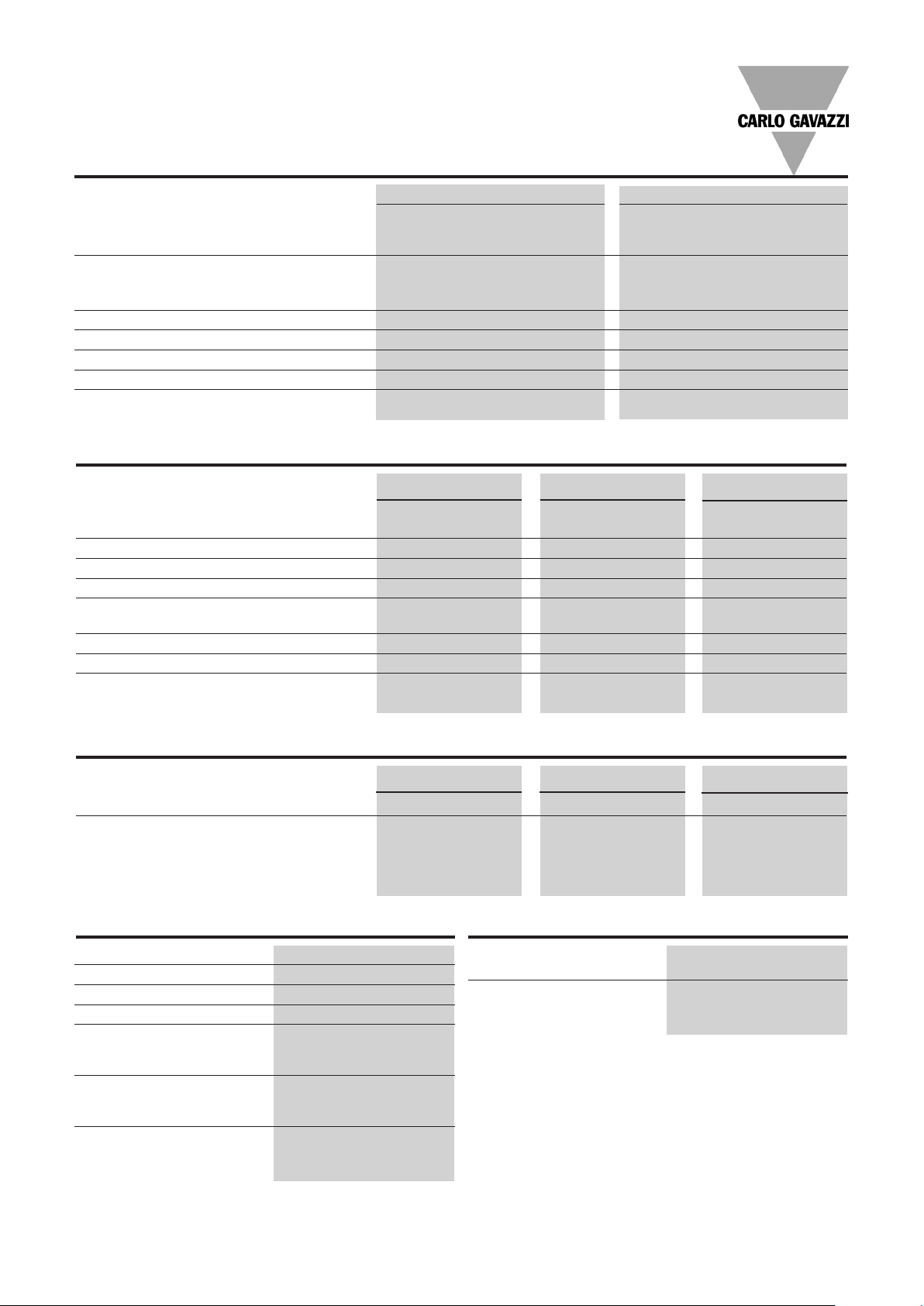
General Spec i fi ca tions
RS1A23... RS1A40... RS1A48...
Operational voltage range 42 to 265 VACrms 42 to 440 VACrms 42 to 530 VACrms
Blocking voltage ≥ 650 Vp ≥ 850 Vp ≥ 1200 V
Zero voltage turn-on ≤ 15 V ≤ 15 V ≤ 15 V
Operational frequency range 45 to 65 Hz 45 to 65 Hz 45 to 65 Hz
Power factor ≥ 0.95 @ 230 VACrms ≥ 0.95 @ 400 VACrms ≥ 0.95 @ 480 VACrms
Approvals UR, cUR, CSA, EAC UR, cUR, CSA, EAC UR, cUR, CSA, EAC
CE-marking Yes Yes Yes
Specifications are subject to change without notice (25.07.2017) 1
p
Page 2
RS1A
Input Specifications
RS1A..D.. RS1A..LA...
Control voltage 18-36 VAC/DC
RS1.23.., 3-32 VDC
RS1.40.., RS1.48.. 4-32 VDC
Pick-up voltage ≤ 18 VAC/DC
RS1.23.., ≤ 2.75 VDC
RS1.40.., RS1.48.. ≤ 3.75 VDC
Reverse voltage ≤ 32 VDC -
Drop out voltage ≥ 1.2 VDC ≥ 5 VAC/DC
Input current @ max input voltage
Response time pick-up ≤ 1/2 cycle ≤ 1 cycle
Response time drop-out ≤ 1/2 cycle ≤ 2 cycles
≤ 12 mA ≤ 15 mA
Output Specifications
RS1A...10 RS1A...25 RS1A...40
Rated operational current
AC51 @ Ta=25°C 10 Arms 25 Arms 40 Arms
Min. operational current 150 mA 150 mA 250 mA
Rep. overload current t=1 s < 12 AACrms < 55 AACrms < 125 AACrms
Non-rep. surge current t=10 ms 100 Ap 325 Ap 600 A
Off-state leakage current @ rated
voltage and frequency < 3 mArms < 3 mArms < 3 mArms
I2t for fusing t=10 ms ≤ 50 A2s ≤ 525A2s ≤ 1800 A2s
On-state voltage drop @ rated current ≤ 1.6 Vrms ≤ 1.6 Vrms ≤ 1.6 Vrms
Critical dV/dt off-state ≥ 500V/µs ≥ 500 V/µs ≥ 500 V/µs
p
Thermal Specifications
RS1A...10 RS1A...25 RS1A...40
Operating temperature -20° to 70°C -40° to 80°C -40° to 80°C
Storage temperature -20° to 80°C -50° to 100°C -50° to 100°C
Housing Specifications
Weight Approx. 60 g
Housing material Noryl GFN 1, black
Baseplate Aluminium
Potting compound None
Relay
Mounting screws M5
Mounting torque 1.5-2.0 Nm
Control terminal
Mounting screws M3 x 9
Mounting torque 0.5 Nm
Power terminal
Mounting screws M5 x 9
Mounting torque 2.4 Nm
Isolation
Rated isolation voltage ≥ 4000 VACrms
Input to output
Rated isolation voltage ≥ 4000 VACrms
Output to case
2 Specifications are subject to change without notice (25.07.2017)
Page 3

RS1A
Heatsink Dimensions (load current versus ambient temperature)
RS....10
Load
current [A]
10.0
3.34 2.58 1.81 1.04 0.27 -
9.0
4.25 3.37 2.49 1.61 0.73 -
8.0
5.41 4.38 3.36 2.33 1.31 0.28
7.0
6.92 5.70 4.49 3.27 2.06 0.84
6.0
8.96 7.49 6.02 4.55 3.08 1.61
5.0
11.9 10.0 8.19 6.36 4.53 2.69
4.0
16.2 13.9 11.5 9.10 6.72 4.34
23.7 20.3 17.0 13.7 10.4 7.12
3.0
38.6 33.4 28.3 23.1 17.9 12.7
2.0
- - - - - 29.7
1.0
20 30 40 50 60 70
Thermal resistance
[K/W]
Power
dissipation [W]
13.0
11.3
9.7
8.2
6.8
5.5
4.2
3.0
1.9
0.9
Ambient temp. [°C]
T
Heatsink Dimensions (cont.)
RS....40
Load
current [A]
Thermal resistance
[K/W]
40
1.73 1.49 1.25 1.01 0.77 0.52 0.28 41
36
2.00 1.73 1.45 1.18 0.90 0.63 0.35 36
32
2.35 2.03 1.71 1.39 1.08 0.76 0.44 31
28
2.80 2.43 2.05 1.68 1.30 0.93 0.55 27
3.41 2.96 2.51 2.05 1.60 1.15 0.70 22
24
4.26 3.71 3.15 2.59 2.03 1.47 0.92 18
20
5.56 4.84 4.12 3.40 2.68 1.96 1.24 14
16
7.74 6.74 5.75 4.76 3.77 2.78 1.78 10
12
12.12 10.58 9.04 7.50 5.96 4.42 2.88 6
8
- - - 15.74 12.56 9.37 6.18 3
4
20 30 40 50 60 70 80
Power
dissipation [W]
Ambient temp. [°C]
RS....25
Load
current [A]
Thermal resistance
[K/W]
25.0
3.23 2.80 2.37 1.94 1.51 1.09 0.66 23
22.5
3.70 3.21 2.73 2.24 1.75 1.26 0.78 21
20.0
4.30 3.74 3.17 2.61 2.05 1.49 0.92 18
17.5
5.07 4.41 3.76 3.10 2.44 1.78 1.12 15
6.12 5.33 4.54 3.75 2.96 2.17 1.38 13
15.0
7.58 6.61 5.64 4.66 3.69 2.72 1.75 10
12.5
9.80 8.55 7.30 6.05 4.80 3.55 2.30 8
10.0
13.5 11.80 10.09 8.37 6.66 4.94 3.23 6
7.5
- 18.3 15.7 13.04 10.39 7.74 5.09 4
5.0
- - - - - 16.2 10.7 2
2.5
A
20 30 40 50 60 70 80
Power
dissipation [W]
T
A
Ambient temp. [°C]
Heatsink Selection
Carlo Gavazzi Heatsink Thermal ...for power
(see Accessories) resistance... dissipation
No heatsink required --- N/A
RHS 300 5.00 K/W > 0 W
RHS 100 3.00 K/W > 25 W
RHS 45C 2.70 K/W > 60 W
RHS 45B 2.00 K/W > 60 W
RHS 90A 1.35 K/W > 60 W
RHS 45C plus fan 1.25 K/W > 0 W
RHS 45B plus fan 1.20 K/W > 0 W
RHS 112A 1.10 K/W > 100 W
RHS 301 0.80 K/W > 70 W
RHS 90A plus fan 0.45 K/W > 0 W
RHS 112A plus fan 0.40 K/W > 0 W
RHS 301 plus fan 0.25 K/W > 0 W
Consult your distribution > 0.25 K/W N/A
Infinite heatsink - No solution
T
A
--- N/A
Specifications are subject to change without notice (25.07.2017) 3
Page 4

RS1A
Dimensions
Applies to RS1A..D.. and RS1A..LA10
Functional Diagram
1(+)
REGULATION
2(-)
DC Control Voltage
1(~)
2(~)
AC Control Voltage
REGULATION
Applies to RS1A..LA25/40 models only.
All dimensions in mm.
3
ZC
4
3
ZC
4
4 Specifications are subject to change without notice (25.07.2017)
Page 5

RS1A
Environmental Information
The declaration in this section is prepared in compliance with People’s Republic of China Electronic Industry Standard SJ/
T11364-2014: Marking for the Restricted Use of Hazardous Substances in Electronic and Electrical Products.
Part Name Toxic or Harardous Substances and Elements
Lead
(Pb)
Power Unit Assembly x O O O O O
O: Indicates that said hazardous substance contained in homogeneous materials fot this part are below the limit requirement of GB/T 26572.
X: Indicates that said hazardous substance contained in one of the homogeneous materials used for this part is above the
limit requirement of GB/T 26572.
Mercury
(Hg)
Cadmium
(Cd)
Hexavalent
Chromium
(Cr(Vl))
Polybrominated
biphenyls (PBB)
Polybrominated
diphenyl ethers
(PBDE)
环境特性
这份申明根据中华人民共和国电子工业标准
SJ/T11364-2014:标注在电子电气产品中限定使用的有害物质
零件名称 有毒或有害物质与元素
铅
(Pb)
功率单元 x O O O O O
汞
(Hg)
镉
(Cd)
六价铬
(Cr(Vl))
多溴化联苯
(PBB)
多溴联苯醚
(PBDE)
O:此零件所有材料中含有的该有害物低于GB/T 26572的限定。
X: 此零件某种材料中含有的该有害物高于GB/T 26572的限定。
25
Specifications are subject to change without notice (25.07.2017) 5
Page 6

Faston terminals
Other Accessories
• Fast-on tabs
• Tab dimensions according to DIN 46342 part 1
• Pure tin-plated brass
• Heatsinks and fans
• Type RHS....
• 0.25 to 5.00 k/W
• Single and dual
relay types
Ordering Key
Screw mounted
Faston terminals
RS, RM Solid State Relay
Faston terminals
Tab orientation
Input Tab width: 4.8mm
Output Tab width: 6.3mm
Faston terminals
in packs of 20
RS, RM Solid State Relay
Tab orientation
*
** 48: 4.8mm faston for input
63: 6.3mm faston for output
RS1A48D25 F 4
RM48 F4
0: Flat (0º)
4: Angled (45º)
• Touch safety cover
• Type RMIP20
• IP20 protection degree
• Pack size: 20 pieces
*
**
*
All accessories can be ordered pre-assembled with Solid State Relays.
Other accessories include DIN rail adaptors, fuses, varistors and spacers.
For futher information refer to Accessories datasheets.
6 Specifications are subject to change without notice (25.07.2017)
 Loading...