

Page 1
Solid State Relays
Analog Full Cycle Switching
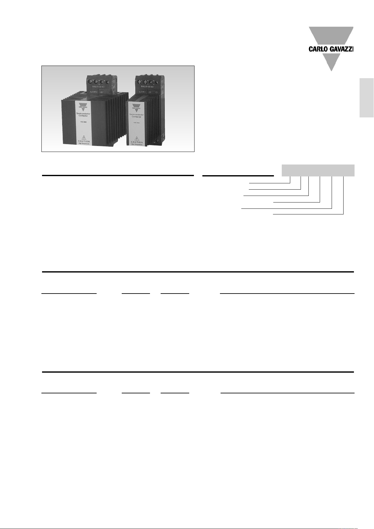
Type RN.F
• AC solid state relay, 1- and 2-poles
• Analog switching for resistive loads (heating)
• 4-20 mA or 0-10 V controls
• Rated operational current: 1-pole : 30A and 50A
2-pole : 2 x15A and 2 x 25A
• Rated operational voltage up to 480 VAC
• LED-indication for normal operation and alarm status
• IP 20 protection
DIN-rail mountable
•
Product Description
The analog switching relay provides a number of full cycles,
evenly distributed over a fixed
period, depending of the control input. The input of 4-20 mA
or 0-10 VDC respectively,
corresponds to zero and full
output within a period of 1.28 s
@ 50 Hz (1.07 s @ 60 Hz). This
principle makes the transfer
characteristics fully linear. The
principle operates with zero
switching, thus ensuring a
reduced level of radiated and
wire conducted noise. The 2pole type has alarm LED indication by loss of master
phase. The analogue Full
Cycle Switching is not recommended for light control due
to light-flickering.
Ordering Key
Solid State Relay
Number of poles
Switching type
Rated operational voltage
Control signal
Rated operational current
RN 1 F 40 V 30
Type Selection, 1-Pole
Rated Control Control Rated operational current
operational voltage input supply 30 A 50 A
120 VAC 4-20 mA RN 1F12I30 RN 1F12I50
230 VAC 4-20 mA RN 1F23I30 RN 1F23I50
480 VAC 4-20 mA RN 1F48I30 RN 1F48I50
0-10 VDC 12-32 VDC, 24 VAC RN 1F12V30 RN 1F12V50
0-10 VDC 12-32 VDC, 24 VAC RN 1F23V30 RN 1F23V50
0-10 VDC 12-32 VDC, 24 VAC RN 1F48V30 RN 1F48V50
Type Selection, 2-Pole
Rated Control Control Rated operational current
operational voltage input supply 30 A Total (2 x 15A) 50 A Total (2 x 25A)
120 VAC 4-20 mA RN 2F12I30 RN 2F12I50
230 VAC 4-20 mA RN 2F23I30 RN 2F23I50
480 VAC 4-20 mA RN 2F48I30 RN 2F48I50
Specifications are subject to change without notice (20.08.2012) 1
0-10 VDC 12-32 VDC, 24 VAC RN 2F12V30 RN 2F12V50
0-10 VDC 12-32 VDC, 24 VAC RN 2F23V30 RN 2F23V50
0-10 VDC 12-32 VDC, 24 VAC RN 2F48V30 RN 2F48V50
Page 2
RN 1F
General Specifications
RN.F12... RN.F23... RN.F48...
Operational voltage range 85 to 140 VAC 85 to 265 VAC 190 to 530 VAC
Blocking voltage 800 V
p
Varistor voltage 275 VAC 275 VAC 510 VAC
Zero voltage turn-on < 10 V < 10 V < 20 V
Operational frequency range 45 to 65 Hz 45 to 65 Hz 45 to 65 Hz
Power factor at rated voltage ≥ 0.9 ≥ 0.9 ≥ 0.9
Average output power 0 to 100% 0 to 100% 0 to 100%
Output power resolution 1/64 of 100% 1/64 of 100% 1/64 of 100%
pprovals UL, cUL, CSA UL, cUL, CSA UL, cUL, CSA
A
CE-marking Yes Yes Yes
800 V
p
1000 V
p
Norms fulfilled EN 60947-1 Low-voltage switchgear and control gear. Part 1- General Rules.
EN 61000-6-1 Generic Immunity Standard. Residential, Commercial & Light Industry Environment
EN 61000-6-2 Generic Immunity Standard. Industrial Environment
Input Specifications
Current controlled input
RN.F..I..
Control current range 4 - 20 mA
Allowable input current 50 mA
Reverse polarity protected Yes
Voltage drop 10 VDC @ 20 mA
Voltage controlled input
Supply voltage range 21 - 27 VAC, 12 - 32 VDC
Supply current 30 mA @ 24 VAC/32 VDC
Control voltage range 0 - 10 V
Control input current 0.1 mA @ 10 VDC
RN.F..V..
Output Specifications
Rated operational current
RN1F.. AC51 @Ta=30°C 30 A 50 A
“ @Ta=40°C 30 A 50 A
“ @Ta=50°C 23 A 38 A
“ @Ta=60°C 20 A 30 A
RN2F.. AC51 @Ta=30°C 30 A total sum (2 x 15A) 50 A total sum (2 x 25A)
“ @Ta=40°C 30 A total sum (2 x 15A) 50 A total sum (2 x 25A)
“ @Ta=50°C 23 A total sum (2 x 11.5A) 38 A total sum (2 x 19A)
“ @Ta=60°C 20 A total sum (2 x 10A) 30 A total sum (2 x 15A)
Zero crossing detection Yes Yes
Min. operational current (per pole) 500 mA 1.8 A
Rep. overload current t=1 s
(Tj init.=25°C) 55 A (rms) 125 A (rms)
Non-rep. surge current t=10 ms
(Tj init.=25°C) < 325 A
Off-state leakage current,
@ rated voltage and frequency
(Tj.=125°C, max.) < 6 mA < 6 mA
I2t for fusing t=10 ms 525 A2s 1800 A2s
Critical dV/dt off-state 500 V/µs 500 V/µs
RN.F..30 RN.F..50
p
< 600 A
p
Thermal Specifications
RN.F..30 RN.F..50
Operational temperature -30° to +70°C (-22° to +158°F) -30° to +70°C (-22° to +158°F)
Storage temperature -30° to +100°C (-22° to +212°F) -30° to +100°C (-22° to +212°F)
Junction temperature < 125°C (257°F) < 125°C (257°F)
R
junction to ambient (AC load) 2.8 K/W 1.7 K/W
th
2 Specifications are subject to change without notice (20.08.2012)
Page 3

RN 1F
L
1A1A2
T
1
4 - 20 mA
+
Current Control
_
L
1
A1A
2
T
1
A3A
4
0 - 10 VDC
+
Voltage Control
_
Control
Supply
L1A1A
2
T
1
4 - 20 mA
+
Current Control
_
L
1
A
1A2
T1A3A
4
0 - 10 VDC
+
Voltage Control
_
Control
Supply
L
2
L
2
T
2
T
2
Housing Specifications
Mounting DIN-rail 35 mm
Weight with RHN1 470 g
Weight with RHN2 780 g
Housing material Noryl SEI, GFN1, Black
LED window material PC Lexan 141R
Base plate Aluminium, nickel plated
Potting compound Polyurethane, Casco Nobel
Terminals
Control terminals nominal 4 mm2or 2 x 2.5 mm
Min. 0.5 mm
Mounting torque max. 0.6 Nm
Power terminals nominal 10 mm
Min. 1 mm
Screw with captive wire clamp
2
AWG 12 or 2 x AWG 14
AWG 6 or 2 x AWG 10
2
, AWG 20
2
or 2 x 6 mm
2
, AWG 16
2
Mounting torque max. 2.0 Nm
Heatsink compound used Electrolube HTS
Dimensions
03
1
Insulation
Rated impulse withstand voltage
Input to output 4000 V
imp
Rated impulse withstand voltage
Output to heatsink 4000 V
i
mp
Environment Specifications
Humidity max. 95%, no condensation
Dimensions
Dimensions (H x W x D)
RN..30 120 x 45 x 110 mm
RN..50 120 x 90 x 110 mm
9
8
103
60
120
4
45
33,7
Wiring Diagrams
37
71,6
RN..30
Note: all dimensions in mm
30
30
60
70
20
120
4
45
37
71,6
70
20
93
72
Note: all dimensions in mm
RN..50
Double-pole relay
Single-pole relay
Specifications are subject to change without notice (20.08.2012) 3
Page 4

V
AC / VDC
A
2
X
X
+
_
A
3
A
4
L
1
T
1
C
/V
L
2
T
2
X
X
A
1
RN 1F
Terminal Layout
1-pole RN.. 2-pole RN..
A
A
2
L
1
T
1
1
A
A
4
3
L
1
T
1
Functional Diagrams
2-pole current controlled input
L
2
T
2
2
1
A
3
A
4
A
A
Master
VAC/VDC (A3, A4only used for voltage control)
control
signal
Slave (2-pole version)
Applications
Single and double pole relay application
Line-Neutral
L
1
L
2
N
Double pole relay in 3-phase application
Star and delta application (Economy Switching only)
L
1
L
2
L
3
4 Specifications are subject to change without notice (20.08.2012)
 Loading...