

Page 1
Specifications are subject to change without notice (03.02.2004) 1
• AC semiconductor contactor
• Zero switching (RJ1A) or
instant-on switching (RJ1B)
1
• Direct copper bonding (DCB) technology
• LED-indication
• Self-lifting terminals
• 2 input ranges: 4-32 VDC and 24-275 VAC/24-48VDC
• Operational ratings up to 30 AACrms and 600 VAC
• Non-repetitive voltage: Up to 1200 V
p
• Opto-isolation > 4000 VACrms
• Over-temperature safety option
2
Product Description
Ordering Key
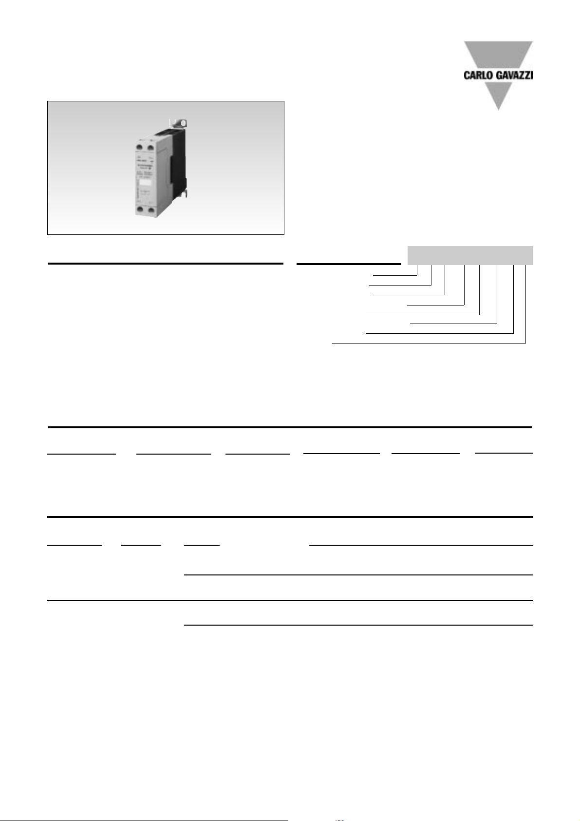
The SOLITRON Mini is a single-phase Solid State
Contactor designed to replace
electro-mechanical contactors
in industrial heating and motor
applications, especially when
switching is frequent. The
product is ready to mount on
DIN-rail or chassis and comes
with integral heatsink. The
standard housing dimensions
enable installation in limited
space and the terminal layout
allows both contactor (E) and
SSR (U) type connection. Two
2.5mm
2
cables can be connected in each screw terminal
to allow looping. A removable
IP20 cover allows connection
of a 4mm
2
cable with crimped
terminal. An LED indicates the
status of the control input.
The superior heat-transfer efficiency combined with a robust
power management system
make this a high reliability
product that can meet the
most stringent functional
requirements.
Solid State Relay
Number of poles
Switching mode
Rated operational voltage
Control voltage
Rated operational current
Terminal layout
Options
Solid State Relays
SOLITRON MINI - With Integrated Heatsink
Types RJ1A, RJ1B
Type Selection
Switching Rated operational Control voltage Rated operational Terminal Layout Options
mode voltage current
A: Zero switching 23: 230 VACrms D: 4-32 VDC 20: 20 AACrms U: SSR P: OverB: Instant-on 60: 600 VACrms A: 24-275 VAC 30: 30 AACrms E: Contactor temperature
switching
1
24-48 VDC protection
2
Rated opera- Non-rep. Control Rated operational current
tional voltage voltage voltage 20 A 30 A 30A+OTP
2
230 VACrms 650 V
p
4 - 32 VDC RJ1A23D20E RJ1A23D30E RJ1A23D30EP
RJ1A23D20U RJ1A23D30U
24 - 275 VAC / 24 - 48VDC RJ1A23A20E RJ1A23A30E RJ1A23A30EP
RJ1A23A20U RJ1A23A30U
600 VACrms 1200 V
p
4 - 32 VDC RJ1A60D20E RJ1A60D30E RJ1A60D30EP
RJ1A60D20U RJ1A60D30U
24 - 275 VAC / 24 - 48VDC RJ1A60A20E RJ1A60A30E RJ1A60A30EP
RJ1A60A20U RJ1A60A30U
Notes
1 RJ1B..: For instant-on version replace RJ1A with RJ1B. Example: RJ1B23D30E. Not available with OTP.
2 “P” suffix: Over-temperature protection (OTP), available on 30A rated devices with type “E” terminals only
Selection Guide
RJ 1 A 60 D 30 E P
Page 2
2 Specifications are subject to change without notice (03.02.2004)
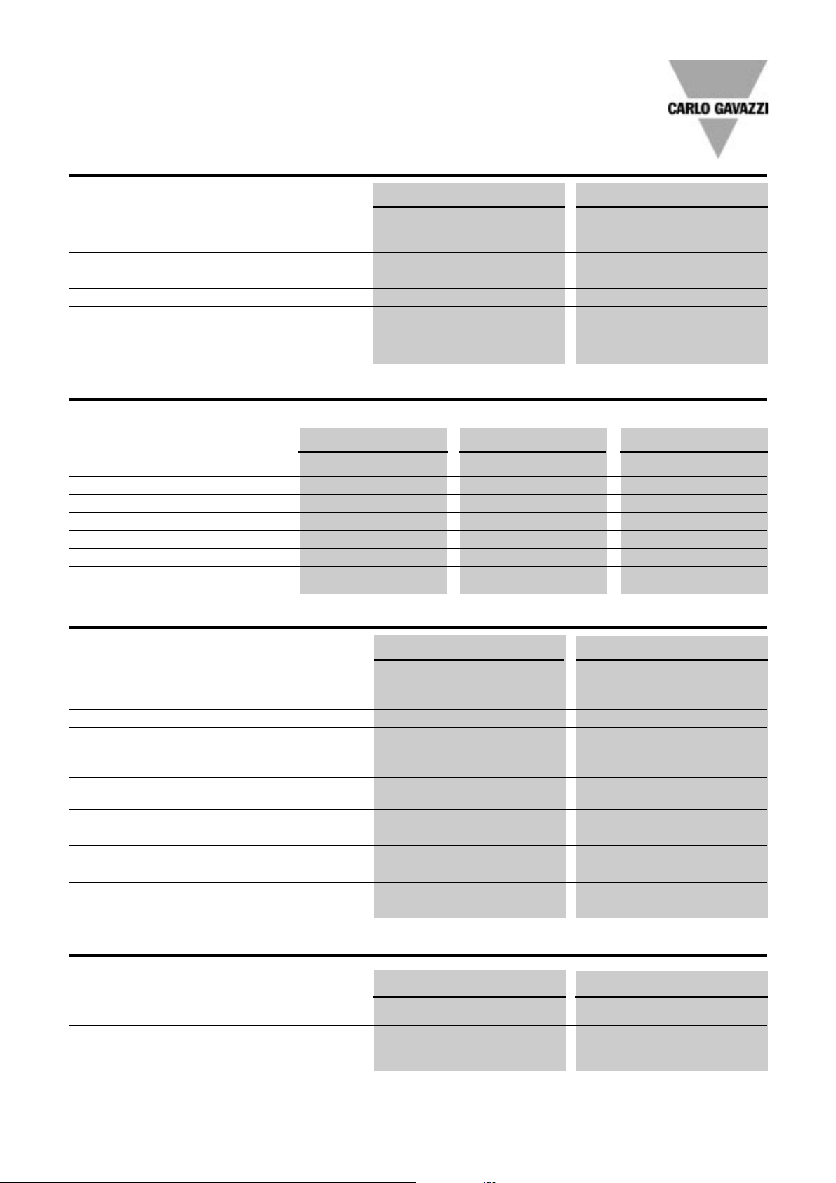
Input Specifications
Output Specifications
RJ1A60D30U
RJ..20 RJ..30
Rated operational current
AC51 @TA=25ºC 20 AACrms 30 AACrms
AC53a @Ta=25°C 5 AACrms 15 AACrms
Min. operational current 350 mAACrms 150mAACrms
Rep. overload current t = 1s < 35 AACrms <125 AACrms
Non rep. surge current Tj(init.)
= 25ºC and t = 10 ms 250 A
p
400 A
p
Off-state leakage current @
rated voltage and frequency < 3 mArms < 3 mArms
I2t for fusing t = 10 ms 310 A2s 1800 A2s
Critical dI/dt ≥ 10 A/µs ≥ 100 A/µs
On-state voltage drop @ rated current 1.6 Vrms 1.6 Vrms
Critical dv/dt commutating 500 V/µs 500 V/µs
Critical dV/dt off-state 500 V/µs 500 V/µs
General Specifications
RJ1.23.. RJ1.60..
Operational voltage range 24 to 265 VAC 42 to 660 VAC
Non-rep. peak voltage 650 V
p
1200 V
p
Operational frequency range 45 to 65 Hz 45 to 65 Hz
Power factor ≥ 0.5 @ 230 VACrms ≥ 0.5 @ 600 VACrms
Vibration 6g (According to EN50155) 6g (According to EN50155)
Approvals UL, cUL, CSA UL, cUL, CSA
CE-marking
Ye s Ye s
RJ1A..D RJ1B.D RJ..A
Control voltage range 4 to 32 VDC 4.5 to 32 VDC 24-275VAC, 24-48 VDC
Pick-up voltage 3.8 VDC 4.25 VDC 22 VAC/DC
Reverse voltage 32 VDC 32 VDC n/a
Drop-out voltage 1.2 VDC 1.0 VDC 6 VAC/DC
Max input current 12 mA 15 mA 17 mA
Response time pick-up 1 cycle 1 ms 1 cycle
Response time drop-out 1 cycle 1 cycle 1 cycle
Thermal Specifications
RJ...D RJ...A
Operating temperature +30 to +70ºC +30 to +70ºC
Storage temperature -40ºC to +100ºC -40ºC to +100ºC
Page 3

Specifications are subject to change without notice (03.02.2004) 3
Terminal Layout
RJ1A.....E RJ1A.....U
Dimensions
RJ1A60D30U
Applications
L
1
L2/N
Single pole relay application
Line-Neutral, Line-Line
L
1
L
2
L
3
N
3 single pole relays in 3-phase application
Delta, Star, Star with neutral
2 single pole relays in 3-phase application
Delta and star connection (economy switch)
Over-temperature Protection (option: ...P)
Control Input*
Green LED
SSR Output
ON
OFF
Red LED
Over-temperature
Sensing
Over-temperature protection is ON
SSR output disabled
Over-temperature
detection
≥ 20 ms
*After over-temperature condition is removed, SSR can be reset by switching OFF the control input for more than 20 ms and switching back ON: this will
*switch ON the SSR output
L1: Phase
T1: Load
A1: Control + or ~
A2: Control - or ~
1L1 4A23A1 3A1
2T1 1L1
2T1 4A2
Page 4

4 Specifications are subject to change without notice (03.02.2004)
Weight Approx. 225 g
Housing material PBT FR
Control terminal cable size
Min 1 x 0.5 mm
2
(1 x AWG20)
Max 2 x 2.5 mm
2
(2 x AWG14)
Mounting torque max. 2 Nm
Power terminal cable size
Min 1 x 0.5 mm
2
(1 x AWG20)
Max 2 x 2.5 mm
2
(2 x AWG14) or
Max (with crimped terminal) 1 x 4 mm
2
(1 x AWG 12)
Mounting torque max. 2 Nm
RJ1A60D30U
22,5 mm
120 mm
Panel Mounting
Insulation
Rated insulation voltage
Input to output ≥ 4000 VACrms
Output to case ≥ 4000 VACrms
Housing Specifications
Derating Curve
Dissipation Curve
RJ Mini Power Dissipation vs Load Current
W
30
20
10
0
0
30
10
20
AACrms
20A
30A
RJ mini derating curves
AACrms
40
30
20
10
0
20
30
40
50
60
70
Deg. C
20A
30A
Connection Example
~
Control Input
(+,~)
LOAD
4A22T1
3A11L1
RJ1A..E
~
(-,~)
Installation
Removable IP20 cover
4mm2 cable with
crimped ring
terminal (lug)
Extraction notch
for cover
Retainer sleeve
 Loading...