


136
136
35.5
51
51
35.5
5
3.2
106
98
90
43.8
9.5
17.8
3.2
106
98
90
43.8
9.5
22.5
RG Solid State Switch
A1
L1
T1A2
ON
A2
A1
1 L1 2
T1
RG Solid State Switch
A1 L1
T1A2
ON
A2
A1
1 L1 2
T1
RG Solid State Switch
A1
L1
T1A2
ON
A2
A1
1 L1 2
T1
RGC...U
5
17.8
106
98
90
43.8
9.5
3.2
98.5
51
35.5
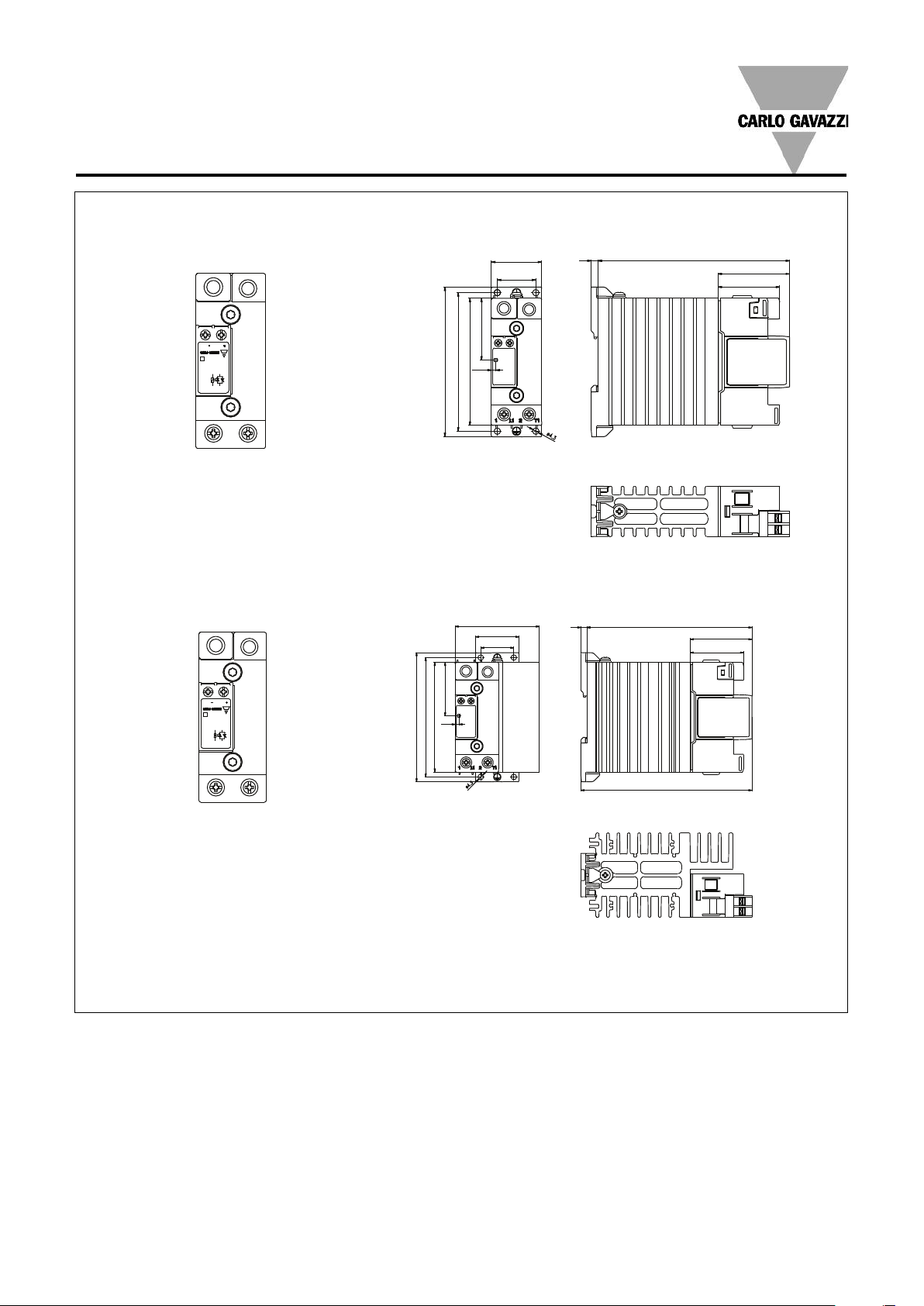
Terminal Layout and Dimensions
RGC...15KGU
RGC...20KGU
RGC...30KGU
1/L1: Supply connection
2/T1: Load connection
A1 (+): Positive control signal
A2 (-): Control ground
* Housing width tolerance +0.5mm, -0mm…as per DIN43880
All dimensions in mm
RGC...U
RG Solid State Switch
A1
L1
T1A2
ON
A2
A1
1 L1
T1
2
140.38
136
5
69.1
35.6
27.2
3.2
106
98
90
43.8
51
43.7
5
3.2
35.6
27.2
106
98
90
43.8
136
43.7
51
RG Solid State Switch
A1
L1
T1A2
ON
A2
A1
1 L1
T1
2
Terminal Layout and Dimensions
RGC...40KGU
RGC...60KGU
1/L1: Supply connection
2/T1: Load connection
A1 (+): Positive control signal
(Positive supply in case of RGC1A..D90GGUP)
A2 (-): Control ground
IN1: Control signal (only for RGC1A.. D90GGUP)
IN2: Fan + supply (only for RGC1A60A90GGUP)
IN3: Fan - supply (only for RGC1A60A90GGUP)
11 + : Alarm output (+)
OUT, 12 - : Alarm output (-)
* Housing width tolerance +0.5mm, -0mm…as per DIN43880
All dimensions in mm

RGC...U
RG Solid State Switch
FAULT
CONTROL
A1
A2
FAN -
FAN +
GND
SUPPLY
CONTROL
ALARM
OUT
IN
3
IN
2
IN
1
1 L1
T1
2
1 L1
T1
2
163
73
5
89.8
69.1
35.6
27.2
73
43.6
126
98
90
60.5
35.6
5
163
43.7
78
27.2
106
98
90
60.5
1 L1
T1
2
RGSolid StateSwitch
FAULT
GRD
CONTROL
A1
A2
11++
SUPPLY
AL
ARM
ALARM
12-
1 L1
T1
2
RGSolid StateSwitch
FAULT
GRD
CONTROL
A1
A2
11++
SUPPLY
AL
ARM
ALARM
12-
69.1
106
98
90
60.5
35.6
27.2
163
5
43.7
78
Terminal Layout and Dimensions (cont.)
RGC...40GGUP
RGC...60GGUP
RGC...90GGUP
1/L1: Supply connection
RGC..D90GGUP
RGC..A90GGUP
2/T1: Load connection
A1 (+): Positive control signal
(Positive supply in case of RGC1A..D90GGUP)
A2 (-): Control ground
IN1: Control signal (only for RGC1A.. D90GGUP)
IN2: Fan + supply (only for RGC1A60A90GGUP)
IN3: Fan - supply (only for RGC1A60A90GGUP)
11 + : Alarm output (+)
OUT, 12 - : Alarm output (-)
* Housing width tolerance +0.5mm, -0mm…as per DIN43880
All dimensions in mm
 Loading...