

Carlo Gavazzi RGC1S, RGS1S Installation Instructions
RGC1S, RGS1S
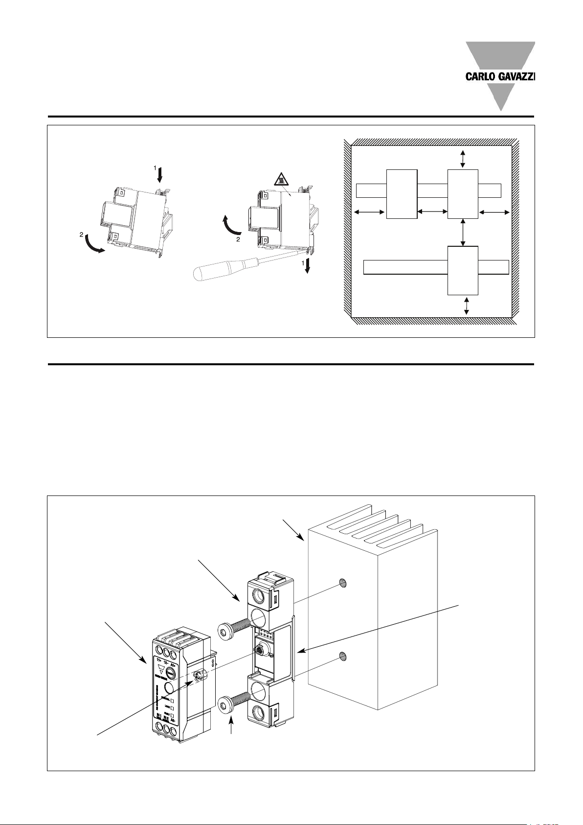
Y2 =
100mm
Y1 = 50mm
50mm
X = 20mm
2
0mm
2
0mm
Mounting on DIN rail
Dismounting from DIN rail
Installation Instructions
Mounting on DIN rail
Dismounting from DIN rail
Mounting Instructions for RGS1S
Thermal stress will reduce the lifetime of the SSR. Therefore it is necessary to select the appropriate heatsinks, taking into account the
surrounding temperature, load current and the duty cycle.
A small amount of thermally conductive silicone paste must be
applied to the back of the SSR. The RG Power Module should be first
mounted on the heatsink with two M5 screws. Gradually tighten each
screw (alternating between the two) until both are tightened with a
torque of 0.75Nm. Then tighten both screws to their final mounting
torque of 1.5Nm.
X
= Refer to
X
Derating vs.
Spacing Curves
X
In case of a thermal pad attached to the back of the SSR, no thermal
paste is required. The RG Power Module is gradually tightened (alternating between the 2 screws) to a maximum torque of 1.5Nm.
Once the power module is tightened to heatsink, the control module
can be mounted on top of the power module and screwed with a
torque of 0.3Nm to ensure good contact between the 2 units.
Heatsink
RG Power Module
Heatsink Compound or
RG Current Sensing
Control Module
Thermal Pad
(not provided with SSR
unless requested)
1 screw M4, Philips PH1
(provided with SSR)
Max. mounting torque: 0.3mm
22 Specifications are subject to change without notice (18.03.2013)
2 screws + washer M5 x 30mm
(not provided with SSR)
Max. mounting torque: 1.5Nm
 Loading...