

Solid State Relays
contactor with Integrated Fuse
Type RGC1F
• Solid State Contactor with integrated fuse
• Zero Cross Switching
Operational voltage: 230 VAC and 600 VAC
•
• 35mm width
• Control voltage: 4 - 32 VDC
• Heater Break and SSR short circuit detection option
• Rated Load Currents of 20 AAC, 30 AAC and 40 AAC
• Alarm Signal Output
• 100 kA short circuit current rating
Product Description
This solid state contactor
includes three functions in one
housing: power switching,
short circuit protection by
semicondcutor fuse and system monitoring. RGC1FA is the
version including the powerswitch and the fuse version
with a fuse while the RGC1FS
includes also the monitoring
function which detects load,
fuse and SSR faults.
The front panel can be opened
for easy access of the fuse and
the fuse holder accepts fuses
from a wide range of manufacturers. Alarms (in RGC1FS) are
indicated by a red LED on the
front and a signal which is normally closed. Product width is
35mm for the whole range and
covers up to 600VAC and
40AAC. Specifications stated at
25°C unless specified.
Ordering Key
RG Solid State Contactor
Number of Poles
Integrated Fuse
Type
Rated Operational Voltage
Control voltage
Rated Operational current
Connection type for control and power
Output Connection configuration
RGC 1 F A 60 D 30 GG E
Ordering Key
Type Integrated Mode Rated Control Rated Connection Connection
Fuse Voltage Voltage Current Control/ Power config.
RGC1 F A: Fuse 23: 230VAC D: 3 or 4.5 - 32VDC 2: 20A G: clamp E: contactor
+ fuse holder 60: 600 VAC 3: 30A
S: Fuse + fuse 4: 40A
holder + system
monitoring
Warning
- Risk of electric shock
- Do not open fuse panel when the product is in operation
- Switch off the panel before doing any maintenance on the product. Panel should be closed before restarting operation.
- Failure to follow these instructions may result in serious injury (or worse) and/or equipment damage
Selection Guide
Voltage Range Options Control Voltage Rated operational current
20 Arms 30 Arms 40 Arms
230Vrms Fuse Only 3 -32VDC RGC1FA23D20GGE RGC1FA23D30GGE RGC1FA23D40GGE
600Vrms Fuse Only 4.5 -32VDC RGC1FA60D20GGE RGC1FA60D30GGE RGC1FA60D40GGE
24 to 240Vrms Fuse +Sensing 3 - 32VDC RGC1FS23D20GGE RGC1FS23D30GGE RGC1FS23D40GGE
42 to 600Vrms Fuse +Sensing 3 - 32VDC RGC1FS60D20GGE RGC1FS60D30GGE RGC1FS60D40GGE
Specifications are subject to change without notice (17.01.2011) 1

RGC
Output Voltage Specifications
RGC1FA23.. RGC1FA60.. RGC1FS23.. RGC1FS60..
Operational Voltage Range 24-240 VAC 42-600 VAC 24-240 VAC 42-600 VAC
+10%, -15% on max)
(
Blocking Voltage 1200 Vp 1200 Vp 1200 Vp 1200 Vp
Internal Varistor 275 V 625 V 275 V 625 V
General Specifications
Latching voltage
(across L1-T1) ≤20V
Operational frequency
range 45 to 65Hz
Power factor 0.5 at rated voltage
Finger Protection IP20
LEDs Control ON: Green, full intensity
Supply ON:
Green, half intensity (RG1CFS only)
Fault: RED (RG1CFS only)
Pollution degree 2
(non-conductive pollution with
possibilities of condensation)
Over-voltage category III
(fixed installations)
Isolation
Input to Output 4000Vrms
Input & Output to Case 4000Vrms
Supply specifications
Rated supply voltage 24 VDC -15%, +20% according
to EN61131-2:2003
Max input current 80 mA during normal conditions
20 mA during Alarm conditions
Alarm Output Specifications (RGC1FS)
Type Open Collector
Rating (@ 40°C) 50mADC, 35VDC
Alarm output onstate voltage
PNP
Normally closed
4
TBD
1, 2
Output specifications
RGC1F20.. RGC1F30.. RGC1F40..
Rated operational current
AC-51 rating @ Ta=40°C 20 AAC 30 AAC 40 AAC
AC-53a rating @ Ta=40°C 4.7 A 6 A 8 A
Number of starts (x:6, Tx:6s, F:50%) at 40˚C
Min. operational current 0.2 A 0.2 A 0.2 A
I2t of integrated fuse @ 690V (size: 14 x 51) 740 A2s 1400 A2s 3100 A2s
Crititcal dv/dt 1000 V/us 1000 V/us 1000 V/us
4
30 30 30
Motor Ratings: HP (UL508) / kW (IEC60947-4-2) @ 40°C
115 VAC 230 VAC 400 VAC 480 VAC 600 VAC
RGC1F..20 1/6HP / 0.18kW 1/3HP / 0.37kW 3/4HP / 0.75kW 1HP / 1.1kW 1-1/2HP / 1.1kW
RGC1F..30 1/4HP / 0.25kW 1/2HP / 0.56kW 1HP / 1.1kW 2HP / 1.5kW 2HP /1.5kW
RGC1F..40 0.37kW 0.75kW 1.5kW 1.5kW 2.2kW
1: DC control to be supplied by a Class 2 power source
2: Power supply specification for RGC1FS across A1, A2 terminals
3: Control input specification for RGC1FA across A1, A2 terminals and for RGC1FS across terminals IN, A2
4: The alarm will open in the case when the power supply is removed.
2 Specifications are subject to change without notice (17.01.2011)
RGC
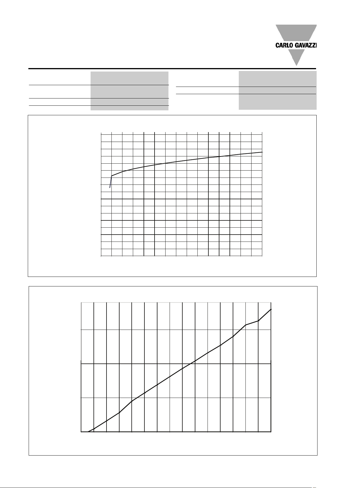
8.1 mA
8.9 mA
9.7mA
1
0.5 mA
11. 3mA
1
2.1 mA
12. 9mA
13. 7mA
0.1 mA
0.9 mA
1.7 mA
2.5 mA
3.3 mA
4.1 mA
4.9 mA
5.7 mA
6.5 mA
7.3 mA
2V 4V 6 V 8V 10V 12V 14
V 16V 18V
Con trol Volta ge ( VDC)
Inp ut C urrent (mA DC)
20 V 22V 24V 26V 28V 30V 32V
1.6mA
0.1mA
0.6mA
1.1mA
2V 4V 6 V 8V 10 V 12V 14V 16 V 18V 20V 22 V 24V 26V 28 V 30V 32V
Con trol Vo ltag e (V DC)
Inp ut C urre nt ( mADC )
Control Input Specifications
1, 3
Control voltage range 3 - 32 VDC (RGC1Fx23)
4.5 - 32 VDC (RGC1Fx60)
Pick-up voltage 3 VDC (RGC1Fx23)
4 VDC (RGC1Fx60)
Drop-out voltage 1.0 VDC
GC1FA...
R
Max Response time pick-up 0.5 cycle
in Response time drop-out 0.5 cycle
M
Max reverse voltage 32 VDC
nput current See diagram below
I
RGC1FS...
Specifications are subject to change without notice (17.01.2011) 3
 Loading...