

Page 1

Specifications are subject to change without notice (30.09.2005) 1
• 2-Pole AC Solid State Relay
• Zero switching
• For resistive and inductive AC loads
• Direct copper bonding (DCB) technology
• LED indication
• Rated operational current: 2 x 25 and 2 x 40AACrms
• Rated operational voltage: 230 - 600VACrms
• Input range: 4.5 - 32VDC
• Non-repetitive peak voltage: Up to 1200Vp
• Opto-isolation: 4000VACrms
Product Description
This 2-pole industrial relay
minimises the space requirements in a control cabinet
without compromising performance. By applying an input
voltage on control A, the corresponding output semicondcutor is activated at the first zero
crossing of the line
Solid State Relay
Number of poles
Zero switching
Rated operational voltage
Control voltage
Rated operational current
Load type
Ordering Key
Solid State Relays
Type Selection
Switching mode Rated operational Rated operational Control Non-rep. Load
voltage current voltage voltage type
A: Zero switching 23: 230VACrms 25: 2 x 25AACrms D: 4.5 - 32VDC 23: 650V
p
M: Inductive
40: 400VACrms 40: 2 x 40AACrms 40: 850V
p
48: 480VACrms 48: 1200V
p
60: 600VACrms 60: 1200V
p
Selection Guide
Rated operational Non-rep. voltage Control voltage Rated operational current
voltage 2 x 25AACrms 2 x 40AACrms
230VACrms 650V
p
4.5 - 32VDC RA2A23D25 RA2A23D40
RA2A23D25M RA2A23D40M
400VACrms 850V
p
4.5 - 32VDC RA2A40D25 RA2A40D40
RA2A40D25M RA2A40D40M
480VACrms 1200V
p
4.5 - 32VDC RA2A48D25 RA2A48D40
RA2A48D25M RA2A48D40M
600VACrms 1200V
p
4.5 - 32VDC RA2A60D25 RA2A60D40
RA2A60D25M RA2A60D40M
Industrial, 2-Pole ZS
Type RA2A
voltage.The same applies to
control B. LEDs indicate the
control status of each pole.
The optimised design is free of
moulding mass to reduce internal mechanical stress.
The RA2A..M types have been
specially customised for
demanding inductive loads.
RA 2 A 48 D 25 M
Input Specifications
Control voltage range 4.5 - 32VDC
Pick-up voltage 4.25VDC
Drop-out voltage 2VDC
Input current per pole
@ max. input voltage ≤10mA
Response time pick-up ≤10ms
@ 50 Hz
Response time drop-out ≤10ms
@ 50 Hz
Weight Approx. 85g
Housing material Noryl GFN 1, black
Base plate
25, 40A Aluminium, nickel-plated
40A (M type) Copper, nickel-plated
FASTONTerminal size 6.3mm
Housing Specifications
Page 2

2 Specifications are subject to change without notice (30.09.2005)
RA2A
Output Specifications
RA2A...25 RA2A...40 RA2A..D25M RA2A..D40M
Rated operational current AC 51 2 x 25AACrms 2 x 40AACrms 2 x 25AACrms 2 x 40AACrms
AC 53a - - 2 x 5AACrms 2 x 15AACrms
Minimum operational current 150mA 150mA 150mA 150mA
Non-rep. surge current t=10 ms 300A
p
390A
p
300A
p
580A
p
Off-state leakage current < 3mA < 3mA < 3mA < 3mA
I2t for fusing t=1-10 ms 450A2s 760A2s 450A2s 1680A2s
On-state voltage drop
@ rated current ≤ 1.6Vrms ≤ 1.6Vrms ≤ 1.6Vrms ≤ 1.6Vrms
Critical dV/dt off-state min. 500V/µs 500V/µs 500V/µs 500V/µs
Zero crossing detection Yes Yes Yes Yes
RA2A23... RA2A40... RA2A48... RA2A60...
Operational voltage range 24 to 265VACrms 42 to 440VACrms 42 to 530VACrms 42 to 660VACrms
Non-rep. peak voltage 650V
p
850V
p
1200V
p
1200V
p
Rated insulation
input -output/output - heatsink 4kV 4kV 4kV 4kV
Operational frequency range 45 to 65Hz 45 to 65Hz 45 to 65Hz 45 to 65Hz
LED ON indication (x2) Yes (green) Yes (green) Yes (green) Yes (green)
Power factor
RA2A ≥ 0.95 @ 230VAC ≥ 0.95 @ 400VAC ≥ 0.95 @ 480VAC ≥ 0.95 @ 600VAC
RA2A..M ≥ 0.50 @ 230VAC ≥ 0.50 @ 400VAC ≥ 0.50 @ 480VAC ≥ 0.50 @ 600VAC
Zero voltage turn-on < 15V < 15V < 15V < 15V
Approvals UL, cUL, CSA UL, cUL, CSA UL, cUL, CSA UL, cUL, CSA
CE-marking Yes Yes Yes Yes
Conformance VDE VDE VDE VDE
General Specifications
Functional Diagram
Dimensions
All dimensions in mm
Page 3

Specifications are subject to change without notice (30.09.2005) 3
0.68 0.56 0.44 0.32 0.19 0.07 82
0.87 0.73 0.59 0.45 0.31 0.17 72
1.10 0.94 0.78 0.62 0.45 0.29 62
1.41 1.22 1.03 0.83 0.64 0.45 52
1.8 1.6 1.36 1.13 0.90 0.67 43
2.3 2.0 1.7 1.4 1.1 0.86 35
3.0 2.6 2.2 1.9 1.5 1.11 27
4 4 3 2.6 2.0 1.5 20
6 6 5 4 3 2.4 13
13 12 10 8 7 5 6
20 30 40 50 60 70
RA2A
Heatsink Dimensions
(load current versus ambient temperature)
RA 2....25/25M
T
A
Ambient temp. [°C]
50
45
40
35
30
25
20
15
10
5
Power
dissipation [W]
Thermal resistance
[K/W]
Load
current [A]
1.11 0.94 0.78 0.62 0.46 0.29 62
1.36 1.17 0.99 0.80 0.61 0.43 54
1.68 1.47 1.25 1.03 0.81 0.60 46
2.06 1.80 1.54 1.29 1.03 0.77 39
2.5 2.2 1.87 1.56 1.25 0.94 32
3.1 2.7 2.3 1.9 1.6 1.17 26
4.0 3.5 3.0 2.5 2.0 1.52 20
6 5 4 3.5 2.8 2.1 14
987643.39
18 16 14 12 9 7 4
20 30 40 50 60 70
RA 2....40
T
A
Ambient temp. [°C]
80
72
64
56
48
40
32
24
16
8
Power
dissipation [W]
Thermal resistance
[K/W]
Load
current [A]
Carlo Gavazzi Heatsink Thermal ...for power
(see Accessories) resistance... dissipation
No heatsink required --- N/A
RHS 300 5.00K/W > 0 W
RHS 100 3.00K/W > 25 W
RHS 45C 2.70K/W > 60 W
RHS 45B 2.00K/W > 60 W
RHS 90A 1.35K/W > 60 W
RHS 45A plus fan 1.25K/W > 0 W
RHS 45B plus fan 1.20K/W > 0 W
RHS 112A 1.10K/W > 100 W
RHS 301 0.80K/W > 70 W
RHS 90A plus fan 0.45K/W > 0 W
RHS 112A plus fan 0.40K/W > 0 W
RHS 301 plus fan 0.25K/W > 0 W
Consult your distribution > 0.25K/W N/A
Infinite heatsink - No solution
--- N/A
Heatsink Selection
RA 2....40M
T
A
Ambient temp. [°C]
100
90
80
70
60
50
40
30
20
10
5
Power
dissipation [W]
Thermal resistance
[K/W]
Load
current [A]
0.41 0.32 0.23 0.13 0.04 - 108
0.55 0.44 0.34 0.23 0.13 0.02 95
0.72 0.60 0.48 0.35 0.23 0.11 82
0.95 0.80 0.66 0.52 0.37 0.23 70
1.25 1.08 0.90 0.73 0.56 0.39 58
1.7 1.5 1.25 1.04 0.83 0.61 47
2.2 1.9 1.6 1.4 1.1 0.82 36
3 2.7 2.3 1.9 1.5 1.14 26
5 4 4 2.9 2.3 1.8 17
10 9 7 6 5 3.6 8
20 17 15 12 10 7 4
20 30 40 50 60 70
Accessories
Heatsinks
DIN rail adapter
Varistors
Fuses
For further information refer
to "General Accessories".
Rated insulation voltage ≥ 4000VACrms
Input to output
Rated insulation voltage ≥ 4000VACrms
Output to case
Insulation
Note: Add the currents of both poles and compare with datasheets for proper heatsink.
Each pole can handle up to the maximum current specified. Example: Each pole of the RA2A23D25 can handle a maximum of 25 A.
Page 4
4 Specifications are subject to change without notice (30.09.2005)
RA2A
Applications
Heat flow
Heatsink
temperature
R
th
j-c
R
th
c-s
Rths-a
Junction
temperature
Case
temperature
Ambient
temperature
This relay is designed for use
in applications in which it is
exposed to high surge conditions. Care must be taken to
ensure proper heatsinking
when the relay is to be used at
high sustained currents. Adequate electrical connection
between relay terminals and
cable must be ensured.
Thermal characteristics
The thermal design of Solid
State Relays is very important.
R
th
c-s = case to heatsink
R
th
s-a = heatsink to ambient
Thermal resistance:
R
th
j-c = junction to case
It is essential that the user
makes sure that cooling is adequate and that the maximum
junction temperature of the
relay is not exceeded.
If the heatsink is placed in a
small closed room, control panel
or the like, the power dissipation
can cause the ambient temperature to rise. The heatsink
is to be calculated on the basis
of the ambient temperature and
the increase in temperature.
Thermal Specifications
RA2A...25. RA2A...40 RA2A...40M
Operating temperature -20° to 70°C -20° to 70°C -20° to 70°C
Storage temperature -20° to 80°C -20° to 80°C -20° to 80°C
Junction temperature ≤ 125°C ≤ 125°C ≤125°C
R
th
junction to case
1 pole 1K/W 1K/W 0.92K/W
2 pole 0.5K/W 0.5K/W 0.46K/W
R
th
junction to ambient ≤ 20K/W ≤ 20K/W ≤ 20K/W
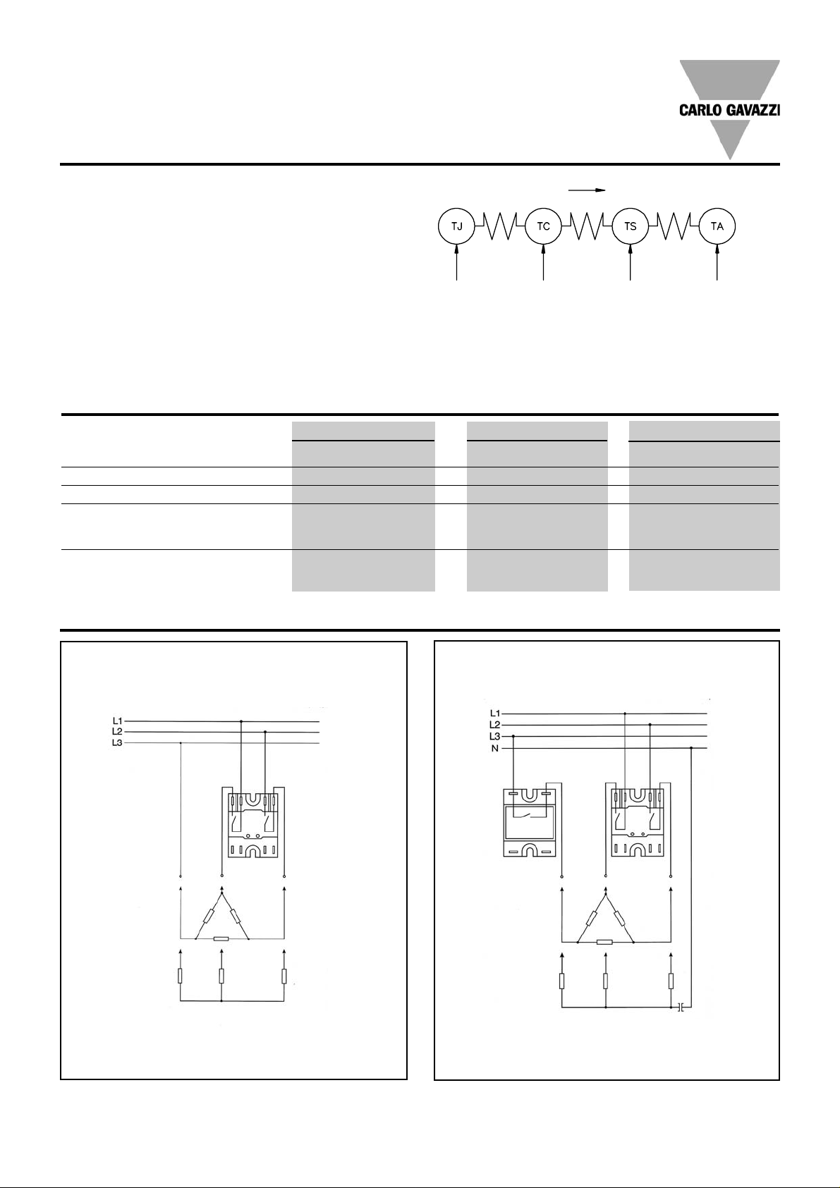
Applications
A single two pole relay in a three phase application.
Star and Delta (Economy switch)
A two pole relay and a single pole relay connected on a
three phase application. Delta, star and star with a neutral point.
 Loading...