

Page 1
Specifications are subject to change without notice 1
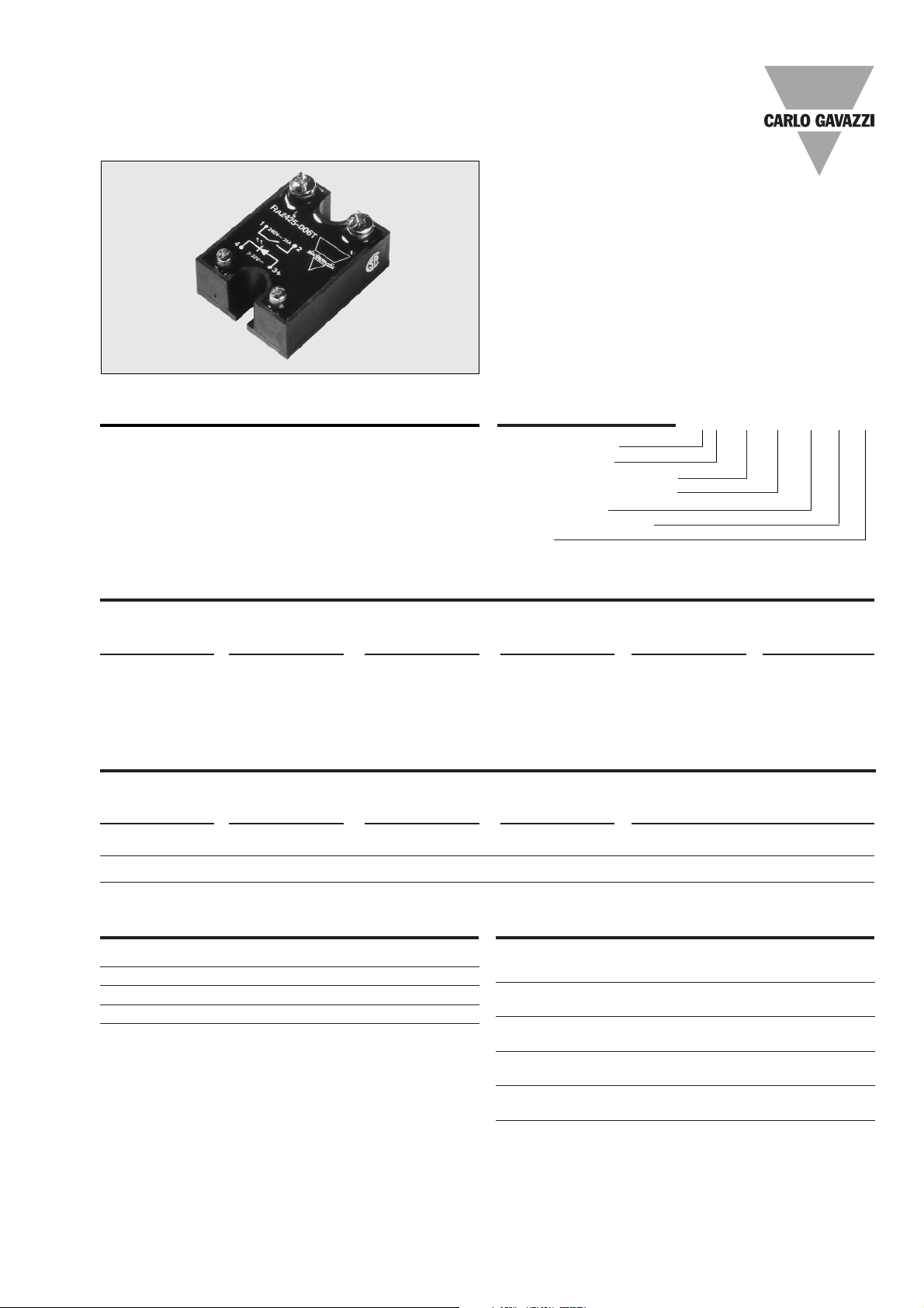
• AC Solid State Relay
• Zero switching
• Low-cost triac type
• Rated operational current: 10 and 25 AACrms
• Non-repetitive voltage: Up to 650 Vp
• Rated operational voltage: Up to 240 VACrms
• Input ranges: 3 to 32 VDC
• Insulation: OPTO (input-output) 4000 VACrms
• Fast-on version available
Product Description Ordering Key
Solid State Relays
Type Selection
Switching mode Rated opera- Rated operational Control voltage Non-rep. voltage Output
tional voltage current
A: Zero switching 24: 230 VACrms 10: 10 AACrms -D: 3 to 32 VDC 06: 650 V
p
T: Triac
25: 25 AACrms TF: Triac/Fast-on
terminals
Solid State Relay
Switching mode
Rated operational voltage
Rated operational current
Control voltage
Non-rep. peak voltage
Output
Selection Guide
Rated operational Non-rep. voltage Terminal Control voltage Rated operational current
voltage type 10 AACrms 25 AACrms
230 VACrms 650 Vp Rivet terminals 3 to 32 VDC RA 2410 -D 06T RA 2425 -D 06T
230 VACrms 650 Vp Fast-on terminals 3 to 32 VDC RA 2410 -D 06TF RA 2425 -D 06TF
General Specifications
Operational voltage range 24 to 280 VACrms
Non-rep. peak voltage ≥ 650 Vp
Operational frequency range 45 to 65 Hz
Power factor ≥ 0.5 @ 230 VACrms
Approvals CSA, UL
Insulation
Rated insulation voltage
Input to output ≥ 4000 VACrms
Rated insulation voltage
Output to case ≥ 4000 VACrms
Insulation resistance
Input to output ≥ 1010Ω
Insulation resistance
Output to case ≥ 1010Ω
Insulation capacitance
Input to output ≤ 8 pF
Insulation capacitance
Output to case ≤ 25 pF
Industrial, 1-Phase ZS
Types RA 24.. -D 06 T, RA 24.. -D 06 TF
RA 24 10 -D 06 T
The triac version of the zero
switching relay is an inexpensive solution for resistive
loads. The zero switching re-
lay switches ON when the AC
sine curve just crosses zero,
and switches OFF when the
current crosses zero.
Page 2

2 Specifications are subject to change without notice
RA 24.. -D 06 T, RA 24.. -D 06 TF
RA 24 .. -D 06T/TF
Control voltage range 3 to 32 VDC
Pick-up voltage ≤ 3 V
Drop-out voltage ≥ 1 V
Reverse voltage ≤ 32 VDC
Input impedance 1.5 kΩ
Response time pick-up ≤ 1/2 cycle
Response time drop-out ≤ 1/2 cycle
Output Specifications
RA 2410 -D 06 T/F RA 2425 -D 06 T/F
Rated operational current AC 1 10 Arms 25 Arms
Minimum operational current 20 mArms 20 mArms
Rep. overload current t=1 s ≤ 30 A
p
≤ 50 A
p
Non-rep. surge current t=20 ms 90 A
p
200 A
p
Off-state leakage current
@ rated voltage, frequency ≤ 5 mArms ≤ 5 mArms
I
2
t for fusing t=1-10 ms ≤ 40 A2s ≤ 200 A
2
s
Critical dI/dt ≥ 10 A/µs ≥ 10 A/µs
On-state voltage drop
@ rated current ≤ 1.6 Vrms ≤ 1.6 Vrms
Critical dV/dt commutating ≥ 10 V/µs ≥ 10 V/µs
Critical dV/dt off-state ≥ 250 V/µs ≥ 250 V/µs
Thermal Specifications
RA 2410 -D 06 T/TF RA 2425 -D 06 T/TF
Operating temperature -40 to +100°C (-40 to +212ºF) -40 to +100°C (-40 to +212ºF)
Storage temperature -40 to +100°C (-40 to +212ºF) -40 to +100°C (-40 to +212ºF)
Junction temperature ≤ 125°C (≤257ºF) ≤ 125°C (≤257ºF)
Rth junction to case ≤ 2.5 K/W ≤ 1.8 K/W
Rth junction to ambient ≤ 12.5 K/W ≤ 12.5 K/W
Control
input
Functional Diagram
Mains input/load output
Load output/mains input
Wiring Diagram
Input Specifications
Control
input
Line/load
Page 3

Specifications are subject to change without notice 3
RA 2410 .. 06 T, RA 24.. -D 06 TF
RA 24 10 .. .. T/F
6.5 5.6 4.7 3.9 3 2.1 12
7.8 6.8 5.8 4.8 3.8 2.8 10
9.2 8 6.9 5.7 4.6 3.4 9
10.8 9.5 8.1 6.8 5.4 4.1 7
- 11.4 9.8 8.2 6.5 4.9 6
- - 12.2 10.2 8.1 6.1 5
- - - - 10.5 7.9 4
- - - - - 10.9 3
------2
------1
20 30 40 50 60 70
10
9
8
7
6
5
4
3
2
1
T
A
Thermal resistance
[K/W]
Power dissipation [W]
Load
current [A]
RA 24 25 .. .. T/F
1.4 1.1 0.77 0.45 - - 32
1.9 1.5 1.2 0.79 0.43 - 28
2.5 2.1 1.6 1.2 0.81 0.39 24
3.3 2.8 2.3 1.8 1.3 0.8 20
4.3 3.7 3.1 2.5 2 1.4 17
5.8 5.1 4.4 3.6 2.8 2.2 14
7.6 6.7 5.7 4.8 3.8 2.9 11
10.5 9.2 7.9 6.6 5.3 4 8
- 14.4 12.3 10.3 8.2 6.2 5
- - - - 17.1 12.8 3
20 30 40 50 60 70
T
A
Ambient temp. [°C]
25
23
20
18
15
13
10
8
5
3
Load
current [A]
Thermal resistance
[K/W]
Power dissipation [W]
Weight Approx. 110 g
Housing material Noryl GFN 1, black
Base plate Aluminium
Potting compound Polyurethane
Relay
Mounting screws M5
Mounting torque ≤ 1.5 Nm
Control terminal
Mounting screws/Fast-on M3 x 6/6.3 x 0.8 mm
Mounting torque ≤ 0.5 Nm
Power terminal
Mounting screws/Fast-on M5 x 6/6.3 x 0.8 mm
Mounting torque ≤ 2.4 Nm
Housing Specifications
Heatsink Selection
Dimensions
** = ±0.4 mm
*** = ± 0.5 mm
**
**
***
*** ***
***
Ambient temp. [°C]
Carlo Gavazzi Heatsink
(see Accessories)
No heatsink required
RHS 100 Assy
RHS 301 Assy
RHS 301 F Assy
Consult your distributor
Thermal resistance
R
th s-a
> 12.5 K/W
3.0 K/W
0.8 K/W
0.25 K/W
< 0.25 K/W
Compare the value found in the current versus temperature
chart with the standard heatsink values and select the heatsink with the next lower value.
Accessories
Protection cover
Heatsinks
DIN rail adapter
Varistors
Fuses
Terminals RA 24.. -D 06 TF
Control terminal (Fast-on) 6.3 x 0.8 mm
Power terminal (Fast-on) 6.3 x 0.8 mm
For further information refer
to "General Accessories".
Heatsink Dimensions (load current versus ambient temperature)
 Loading...