

Page 1
OUR PRODUCTION SITES
Carlo Gavazzi Industri A/S
Hadsten - DENMARK
Inductive and Capacitive
Proximity
Sensors in full metal and
plastic
housings. Photoelectric
Sensors.
Level Sensors: Optical,
Conductive
and Capacitive.
Ultrasonic Sensors and
Magnetic
Switches. Limit Switches.
Dupline Field and Installation
Bus.
Building Automation Systems.
Carlo Gavazzi Ltd
Zejtun - MALTA
Solid States Relays.
Versions for PCB and panel
mounting.
AC Semiconductor Motor
Controllers
Soft starters.
Industrial and PCB Relays.
Carlo Gavazzi Controls SpA
Belluno - ITALY
Energy Management.
Timers and Monitoring
Relays.
Digital Panel Meters and
Temperature Controllers.
SAIET Elettronica SpA
Castel Maggiore (BO) - ITALY
Safety and Magnetic
Switches,
Safety Modules.
Mat Systems, Light Curtains,
Electrical Transient,
Protections.
Measuring Systems and
Encoders.
Software for PQT90 data download and configuration
CARLO GAVAZZI
Automation Components
OUR SALES NETWORK
Carlo Gavazzi GmbH
Wien - AUSTRIA
Carlo Gavazzi NV/SA
Vilvoorde - BELGIUM
Carlo Gavazzi Inc.
Mississauga, ON - CANADA
Montreal, PQ - CANADA
Carlo Gavazzi Handel A/S
Hadsten - DENMARK
Carlo Gavazzi OY AB
Helsinki - FINLAND
Carlo Gavazzi Sarl
Roissy - FRANCE
Carlo Gavazzi GmbH
Weiterstadt - GERMANY
Carlo Gavazzi UK Ltd
Aldershot - GREAT BRITAIN
Carlo Gavazzi SpA
Lainate (MI) - ITALY
Carlo Gavazzi Automation Sdn Bhd
Petaling Jaya, Selangor - MALAYSIA
Carlo Gavazzi BV
Beverwijk - NETHERLANDS
Carlo Gavazzi AS
Porsgrunn - NORWAY
Carlo Gavazzi Lda
Lisboa - PORTUGAL
Carlo Gavazzi SA
Leioa (Bizkaia) - SPAIN
Carlo Gavazzi AB
Karlstad - SWEDEN
Carlo Gavazzi AG
Steinhausen - SWITZERLAND
Carlo Gavazzi Inc.
Buffalo Grove IL - USA
Further information on www.carlogavazzi.com
CARLO GAVAZZI
Automation Components
PqtSoft Network-Remote
PQT-90
INSTRUCTION MANUAL
Page 2

PQT-90: Modular network power
quality transducer
Harmonic analysis; Energy meters;
Plug and play module system;
SMS reception and transmission.
These are only a few among the
functions of PQT-90. What’s more,
Carlo Gavazzi means ISO9001 certification, a working experience of
many decades and a world-wide
organization. All this because we
want our customers to have the
top products and the top service.
Welcome in the Carlo Gavazzi world
and compliments for your smart
choice. Visit our Website and evaluate our wide range of products:
www.carlogavazzi.com/ac
T
H
A
N
K
Y
O
U
F
O
R
C
H
O
O
S
I
N
G
C
A
R
L
O
G
A
V
A
Z
Z
I
CARLO GAVAZZI
Automation Components
S
M
S
m
e
ssa
ge
s
Page 3
Index
4
3
2
Warnings
PQTSoft Remote
SETUP . . . . . . . . . . . . . . . . . . . . . . . . . . . . . . . . . . . . .05
■ PQTSoft Remote Setup . . . . . . . . . . . . . . . . . . . .05
■ PQTSoft Remote Uninstall . . . . . . . . . . . . . . . . . . .05
■ PQTSoft Remote in brief . . . . . . . . . . . . . . . . . . . .06
CONFIGURATION . . . . . . . . . . . . . . . . . . . . . . . . . . . . .08
■ Main menu . . . . . . . . . . . . . . . . . . . . . . . . . . . . . .08
❑
Configuration archive and remote PQT programming
. . .08
❑ Instrument composition... . . . . . . . . . . . . . . . .09
❑ Instrument working mode, clock and system setup .10
❑ Digital input working mode setup . . . . . . . . . .12
❑ Harmonics analysis and digital filter setup . . .13
❑ Setup of min-max values logging + rel. variables . .15
❑ Logging variables selection + dmd power calculation . .16
❑ Tariffs and installed power setup . . . . . . . . . .18
❑ Dual-tariff setup . . . . . . . . . . . . . . . . . . . . . . .19
❑ Multi-tariff setup . . . . . . . . . . . . . . . . . . . . . . .21
❑ Multi-tariff setup with digital inputs . . . . . . . . .23
❑ Digital output setup . . . . . . . . . . . . . . . . . . . .24
❑ Digital output alarm setup . . . . . . . . . . . . . . .26
❑ Analogue output alarm setup . . . . . . . . . . . . .27
❑ Set SMS messages and phone numbers . . . . . . .30
TRANSMISSION OF THE CONFIGURATION . . . . . . . .32
■ Transmit the configuration . . . . . . . . . . . . . . . . . .32
❑ Communication setup . . . . . . . . . . . . . . . . . .33
❑ Phone numbers and dialling properties . . . . .34
❑
Network address and warning messages
. . . . . .35
■ Reading of instantaneous variables . . . . . . . . . . . . . .35
LAST FUNCTIONS . . . . . . . . . . . . . . . . . . . . . . . . . . . .36
■ Reset of partial and total meters. . . . . . . . . . . . . .36
■ Automatic modem configuration. . . . . . . . . . . . . .36
■ Selection of connections and setting of dialling properties 37
❑ Dialling properties. . . . . . . . . . . . . . . . . . . . . .38
PQTSoft Remote and Network, PQT-90 modular
quality network transducer, Instruction manual:
FW rev. 01 CARLO GAVAZZI Controls SpA
We suggest you to keep the orginal packing in case
it is necessary to return the instrument to our
Technical Service Department. In order to achieve
the best results with your instrument, we recommen
you to read this instruction manual carefully. When opening
the packing, verify that the product is not damaged and that
the following material is included: 1 PQT-90, 1 CD-ROM with
the programming software, 1 instruction manual (one RS232
serial connection cable). PQT-90 must be equipped with all the
modules necessary for its correct use. Before using the instrument, follow the instructions on page 40.
MEANING OF THE SYMBOLS USED IN THIS MANUAL
See correlated subject on page ...
Chapter starts on page...
Chapter ends on page...
Particularly important subject or information
More details are given on the current subject
99
99
Page 4
Setup
5
PQTSoft Remote
4
Index
3
PQT-90
INSTALLATION . . . . . . . . . . . . . . . . . . . . . . . . . . . . . . .40
■ Overall dimensions, DIN-rail mounting . . . . . . . . . . . . .41
■ Position of slots and relevant modules . . . . . . . . .42
■ Connection of optional modules . . . . . . . . . . . . . .45
■ Electrical diagrams . . . . . . . . . . . . . . . . . . . . . . . .49
Useful info . . . . . . . . . . . . . . . . . . . . . . . . . . . . . . . . . .53
■ Data logging operating principle and duration . . .53
■ Appl. bar: meaning of the icons . . . . . . . . . . . . . .56
■ How to use SMS messages . . . . . . . . . . . . . . . . .56
TECHNICAL FEATURES . . . . . . . . . . . . . . . . . . . . . . . .59
PQTSoft Network
PRELIMINARIES . . . . . . . . . . . . . . . . . . . . . . . . . . . . . .68
■ Installing PQTSoft Network . . . . . . . . . . . . . . . . .68
■ The software in brief . . . . . . . . . . . . . . . . . . . . . . .69
CONFIGURATION . . . . . . . . . . . . . . . . . . . . . . . . . . . . .72
■ Main menu . . . . . . . . . . . . . . . . . . . . . . . . . . . . . .72
■ Configuration of automatic data download . . . . . .73
❑ Setting of communication parameters . . . . . .73
❑ Selection of phone numbers and diall. prop. .74
❑ Folder selection for data files, counter . . . . . . .
file and event file . . . . . . . . . . . . . . . . . . . . . .75
❑ If “Local network of instruments” was selected . .76
❑ Setting expiry date for automatic data download . . .76
■ Configuration of data manual download . . . . . . . .78
❑ Communication setup . . . . . . . . . . . . . . . . . .78
❑ Selection of phone numbers and setting of . . .
dialling properties . . . . . . . . . . . . . . . . . . . . .79
❑ Define file name for downloaded data . . . . . .80
❑ Selection of “Local network instrument” . . . . .81
■ Reading of instantaneous variables . . . . . . . . . . .82
LAST FUNCTIONS . . . . . . . . . . . . . . . . . . . . . . . . . . . . . . . . . . . . .84
■ Configuration of analogue modem and GSM . . . .84
■ Contact management . . . . . . . . . . . . . . . . . . . . . .85
■ PQT-90 data conversion in excel format . . . . . . . .88
Main menu
7
8
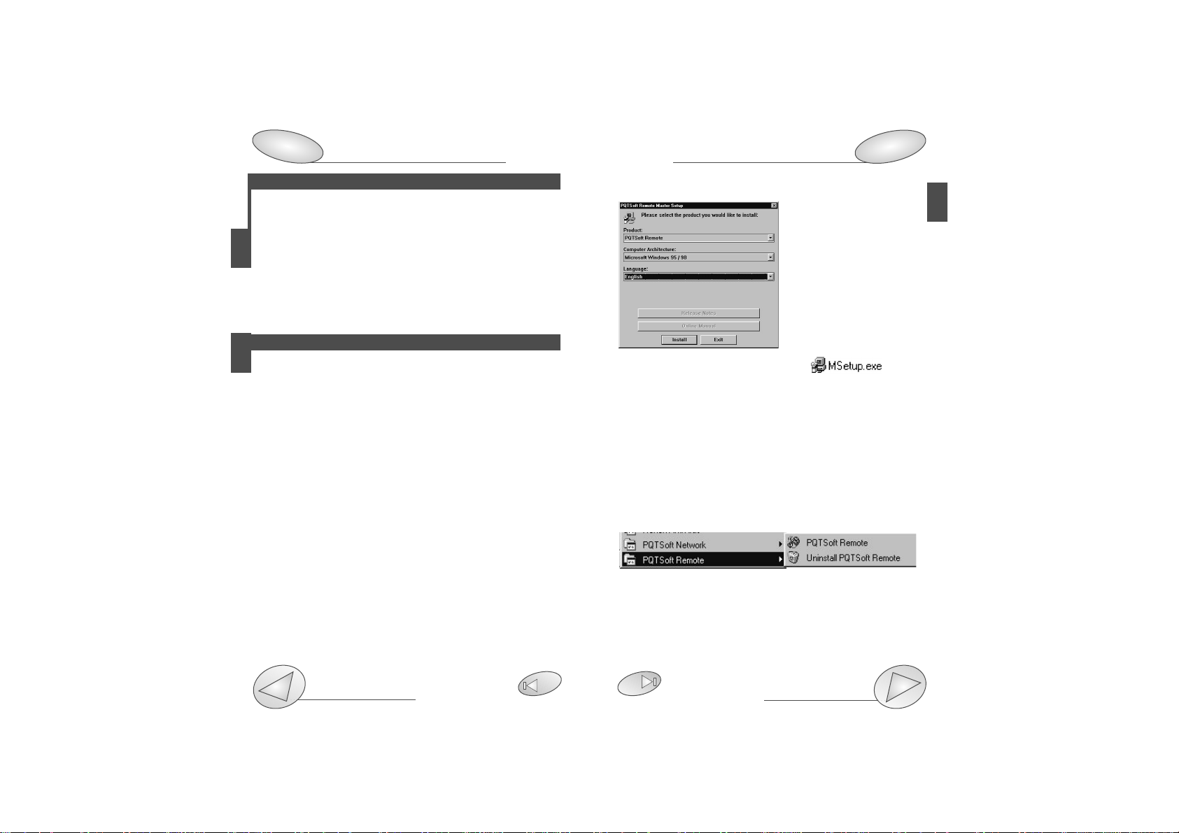
■PQTSof Remote setup
When the CD-ROM is
inserted, the setup programme is automatically
executed (the CD-ROM
drive is to be enabled) and
the box on the left is displayed.
If the setup will not run,
click on the right key of
the mouse and select the
“explore CD-ROM” command: then, double click
the icon
to manually execute the application.
Afterwards, choose the operating system and the desired
language from the drop-down menu (see picture above).
Press “Install” to carry on with the installation following the
“instructions” given in the following dialog boxes. Save all
current jobs and close all open applications before
installing PQTSoft Remote.
■“PQTSoft Remote” Uninstall
Select “Uninstall PQTsoft Remote” to start the guided uninstallation of PQTSoft.
Page 5

PQTSoft Remote
Setup
Communication setup
33
7
PQTSoft Remote
6
Setup
5
■PQTSoft Remote in brief
PQTSoft Remote has been conceived to program PQT-90
by means of a data transmission from the PC to the instrument via RS232 or RS485 serial interface. The choice
between one interface or the other is therefore very important for the correct operation of the instrument as shown
by the following figure:
Local single PQT connected to
the PC by RS232 serial port
Maximum 255 PQT’s in an RS485 local network connected
to the PC by RS232 thanks to the RS485-RS232 SIU-PC
converter.
Maximum 100 remote single PQT’s connected to the PC by
means of a telephone network thanks to an analogue/GSM
modem.
Maximum 25000 PQT’s in max 100 remote RS485 networks
connected to the PC by means of a telephone network and
RS485-RS232 SIU-PC.
RS232
RS485RS485
SIU-PC
RS232
... MAX255
RS232 RS232
MODEM
MODEM
Telephone network
... MAX100
RS232 RS232
Telephone network
RS485
MODEM MODEM SIU-PC
... MAX100
... MAX255
... MAX255
Page 6
PQTSoft Remote
Configuration
Available modules
29
42
9
■Main menu
1- Drop-down menu of the functions
2- Programming of PQT-90 and programming start-up
3- Reading of instantaneous variables (page 35)
4- Reset of all the water and gas energy meters (page 36)
5- Automatic configuration of analogue modem (page 36)
6- Automatic configuration of GSM modem (page 36)
7- Contact management (page 37)
8- Programme status.
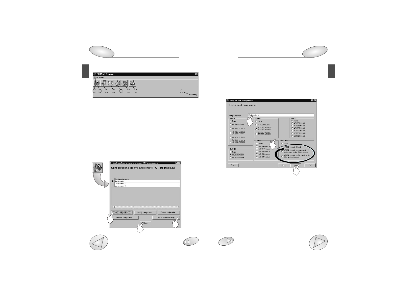
■Configuration of PQT-90
❑Configurations archive and remote PQT programming
PQTSoft Remote
8
Configuration
1
3
4
5
2
2
1
3
PQTSoft Remote manages a configuration archive that may be
selected at any time. At first, when the software has just been
installed, this file is empty. [1] Click on new configuration to start
the programming procedure of PQT90. [2] It allows to load from
PQT-90 the pre-existing programming and to modify it, if
required. [3] Close the window without modifications.
❑Instrument composition...
[1] Enter the name required for the new configuration of PQT-90.
[2] Select the supplied modules installed in the instrument in
the various slots. For the module AR1041 only, if it is present,
also the operating mode is to be indicated as follows:
“AR1041 module (slave)”: PQT-90 is enabled to the datadownload only on request of the user;
“AR1041 module with analogue or GSM (Master+Slave)”
modem: PQT-90 is enabled to the data download on request
and to the independent transmission of SMS in case of
alarm activation;
“AR1041 module with GSM modem for SMS (Master)”:
PQT-90 is enabled to transmit SMS messages and to send
8
6
7
2
1
3
Page 7
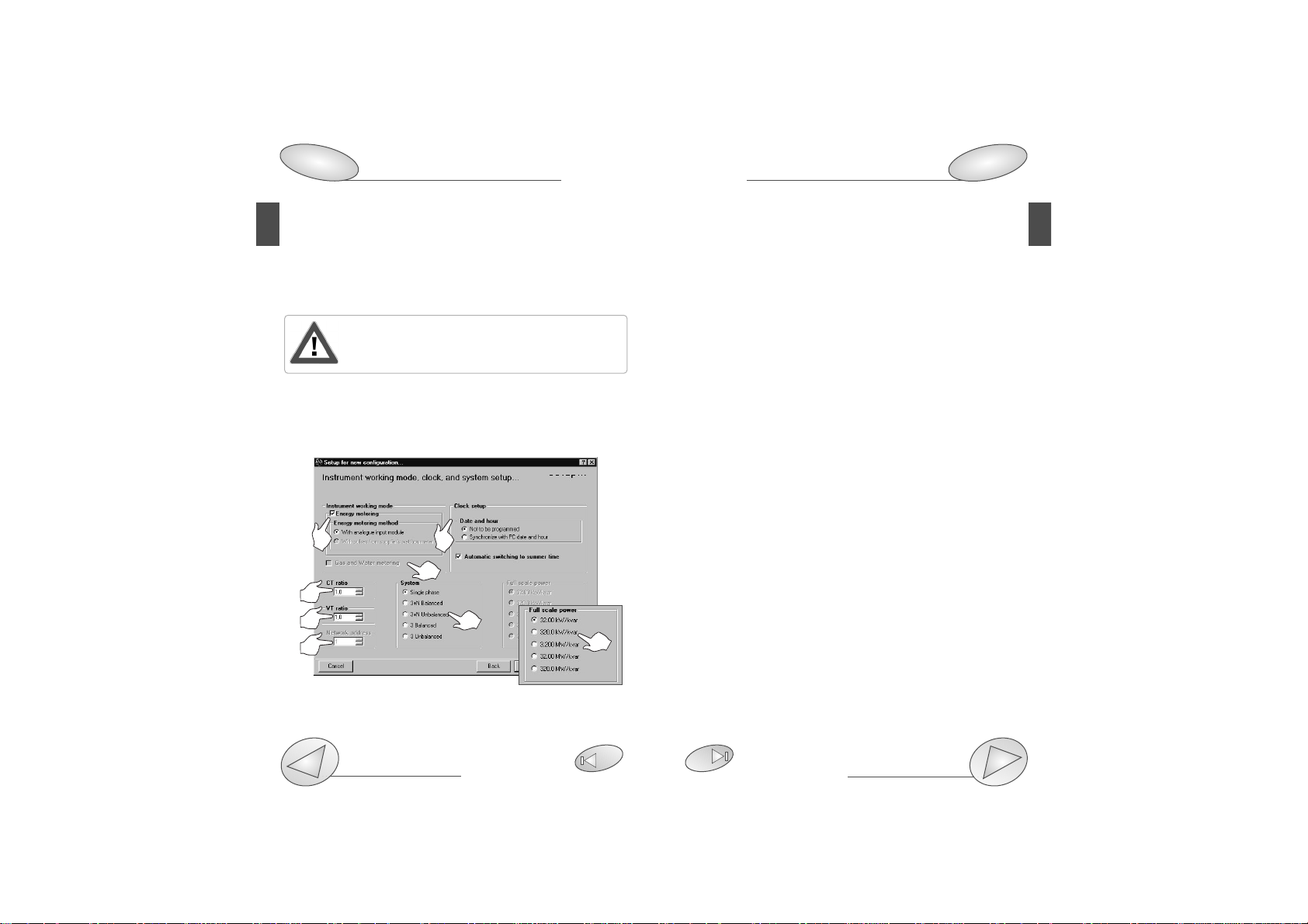
or without analogue measuring inputs (AQ1018, AQ10109)
[2] Enables the gas and water metering.
[3] Selects the ratio of the current transformer. Example: if
the CT (current transformer) primary has a current of 300A
and the secondary a current of 5A, the CT ratio corresponds
to 60 (that results from: 300/5).
[4] Selects the value of the VT (voltage transformer) ratio.
Example: if the VT primary connected to the instrument is
20kV and the secondary is 100V, the VT ratio corresponds
to 200 (resulting from 20000/100).
[5] Selects the serial address of the instrument when the latter is part of a network of instruments.
[6] Selects the type of electrical system. If no measuring
inputs (AQ1018, AQ1019) have been selected on the previous page, the box “Full scale power” will appear: select the
most appropriate full scale.
[7] Selects the options for the clock of PQT-90. If the option
“Not to be programmed” is selected, the clock will not be
programmed; to program the hour, select the option
“Synchronize with PC date and hour”, the clock will be programmed with the date and hour present in the system of
the PC. To make the instrument automatically switch to the
summer time and viceversa, select the option “Automatic
switching to summer time”.
PQTSoft Remote
29
11
SMS messages when an alarm occurs. To carry out the data
download, in this case, it is necessary to use the RS485
serial module.
[3] Click this button to continue the configuration of PQT-90.
The following windows will vary according to the
modules selected in the box “Instrument composi-
tion...” (see previous page).
❑Instrument working mode, clock and system setup
[1] Enables the energy metering. Select the alternative with
Configuration
PQTSoft Remote
10
Configuration
8
1
7
3
4
6
2
5
6
Page 8
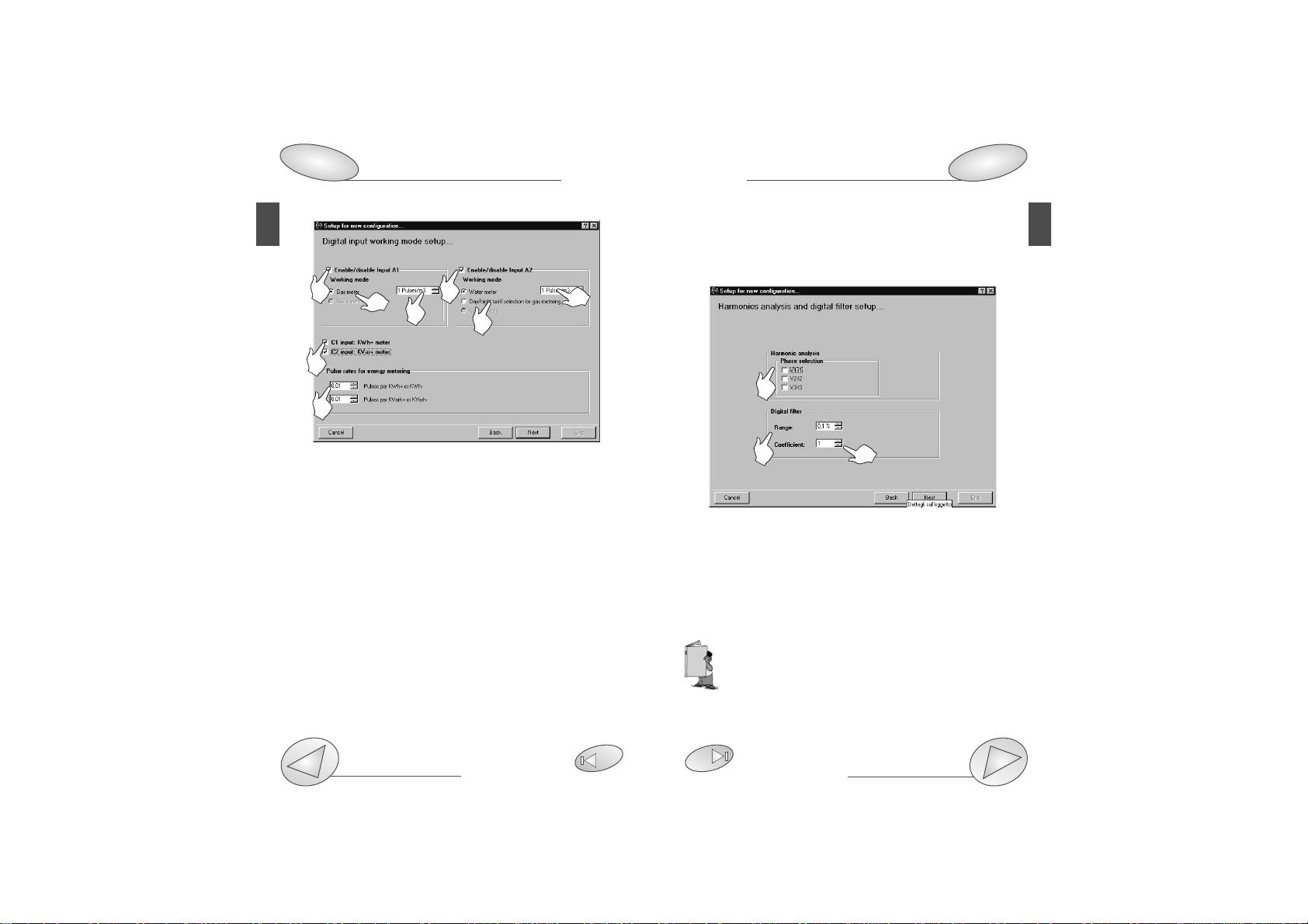
and C2 are not available if PQT-90 is supplied with analogue measuring inputs AQ1018 or AQ1019.
❑Harmonics analysis and digital filter setup
[1] Enables the harmonic analysis on the selected phases,
activate the relevant check boxes.
[2] Selects the value of the “Range” parameter of the digital filter.
[3]
Selects the value of the “coefficient” factor of the digital filter.
Example: the value of the V
L-N
variable fluctuates between 222V
and 228V and it is therefore necesarry to stabilize it. The parameters of the digital filter must be set as follows:
• RANGE: the variable has fluctuations within the average value
whose amplitude is equal to ±1,3% of the rated value of the
variable itself (where ±1.3% results from (228-222)/ 2= ±3V,
then ±3*100/231V= ±1.3%; 231V being the rated phase-neu-
tral value of a 400V input). The “range” parameter is the action
range of the digital filter and it is set at a value slightly higher than the
percentage amplitude of the fluctuation: e.g. 1.5%.
❑Digital input working mode setup
[1] Enables digital input A1 (input 1 of the digital input module installed in slot A of PQT-90);
[2] Enables digital input A1 working mode: “Gas meter” or
“kWh- meter”.
[3] Set the amount of the input pulse (pulse/m
3
ex.: if the
value 10 has been set, then 10 input pulses will be required
for the following gas metering: 1m
3
).
[4] Enables digital input A2 (input 2 of the digital input module installed in slot A of PQT-90);
[5] Choose digital input A2 working mode: “Water meter”,
“Day, night tariff of the gas meter” or “kvarh- meter”.
[6] Set the amount of the input pulse (pulse/m
3
ex.: if the
value 10 has been set, then 10 input pulses will be required
for the following metering: 1m
3
).
[7] Enables digital input C1 to the function of kWh meter, C2
to the function of kvarh meter;
[8] Set the amount of the input pulse (pulse/kWh, kvarh ex.:
set the value 10: 10 input pulses will be necessary for the
energy metering of 1kWh, 1kvarh). The input pulses C1
PQTSoft Remote
Configuration
Digital inputs connection
29
45
13
PQTSoft Remote
12
Configuration
8
1
2
3
1 4
7
8
2
6
3
5
Page 9
PQTSoft Remote
Configuration
29
15
PQTSoft Remote
14
Configuration
8
• COEFFICIENT: if the new value acquired by the instrument is
within the action range of the filter, then the new displayed value
will result from the sum of the previous value (A) to the variation
(B) divided by the filtering coefficient (C), that is: [(A) + (B/C)]. As
a consequence, a value higher than this coefficient, will result in
a higher settling time and therefore a higher stability. Generally,
the best result will be obtained by setting the filtering coefficient
to a value equal to at least 10 times the value of the range
parameter. In the example above: 1.5*10=15. To improve the
stability, the filtering coefficient can be increased: the admitted
values are within 1 and 255.
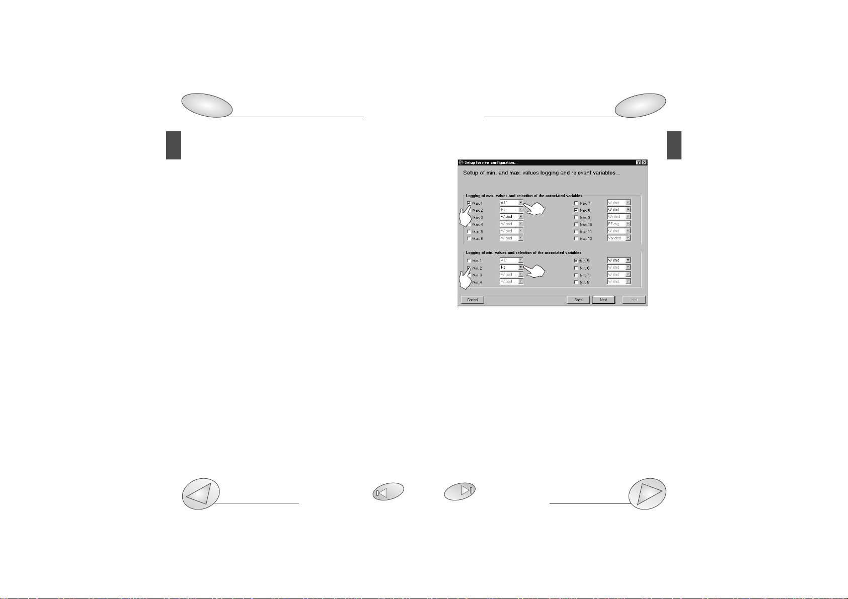
❑Setup of min. and max. values logging and relevant variables
This dialog box allows to associate some variables to the
automatic logging of max and min values (from Max. 1 to
Max. 12 and from Min. 1 to Min. 8).
[1] Select the data to be logged activating the relevant
check box.
[2] Select the variable to be logged among those available
in the drop-down list that will appear after clicking on the
arrow on the right of the box.
1
2
1
2
Page 10
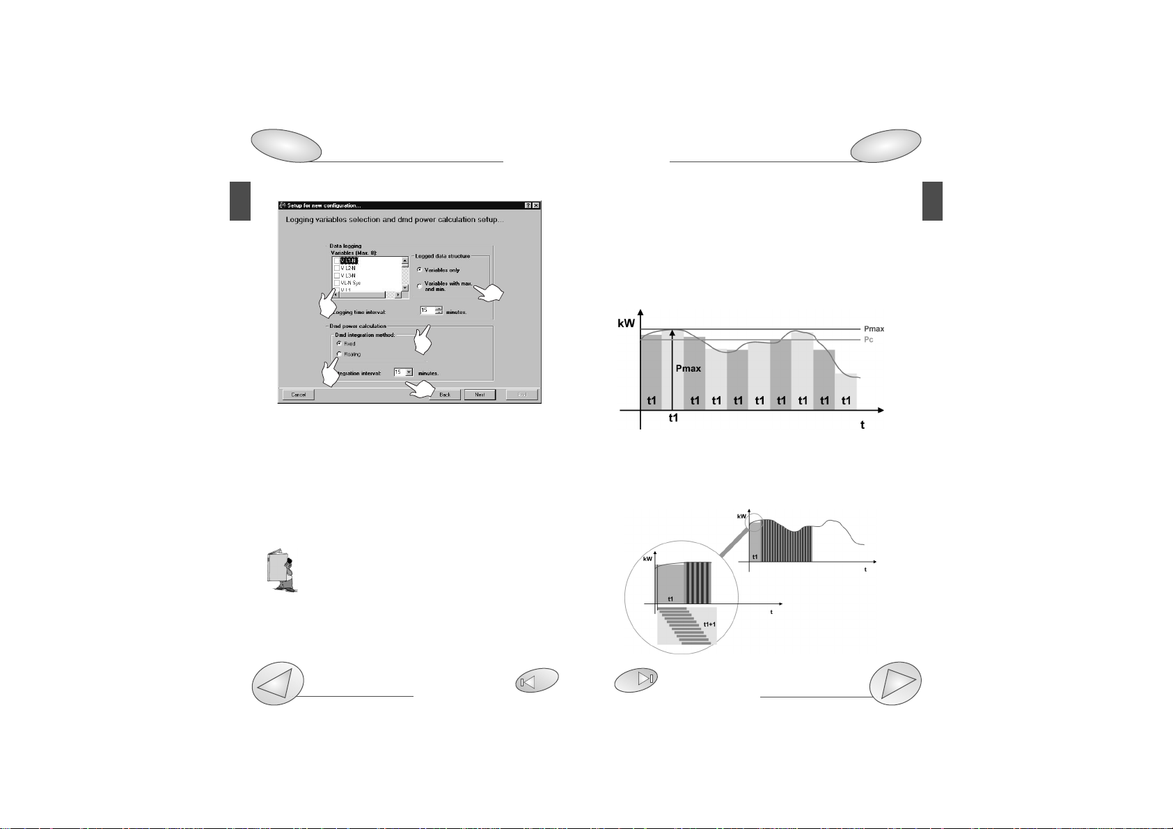
❑Logging variables selection and dmd power calculation
This window allows the user to enable the variables to be
logged (Max 8) in the data memory of PQT-90 and the working mode of this operation.
[1] Select the variables to be logged (Max8) activating the
relevant check boxes.
[2] Select if, in addition to the logging of the average values of the
variables, PQT-90 is required to log also the min and max values in
the time interval.
[3] Select the value of the logging time interval (from 1 to 60 min.)
During the measurement, the instrument takes samples of the selected variables every 200ms approx; at
the expiry of the set time interval, the instrument cal-
culates the average of the samples and carries out the
data logging. The historical value will therefore be guaranteed
to be highly accurate.
[4] Selects the dmd (W-VA-var-PF) calculation method
between FIXED and FLOATING.
FIXED SELECTION: if a value of 15 minutes is selected, the
PQTSoft Remote
Configuration
Data Logging and relevant duration
29
53
17
PQTSoft Remote
16
Configuration
8
1
2
3
4
5
instrument calculates the dmd value and updates it every 15 minutes.
FLOATING SELECTION: if for example the value “15 minutes” is
selected, the instrument calculates the dmd value and updates
its value at first after 15 minutes and then every minute generating a window whose width corresponds to 15 minutes and shifts
by units of 1 minute.
The following diagrams show the two working methods.
FIXED DMD POWER CALCULATION
FLOATING DMD POWER CALCULATION
Where: Pmax is the maximum measured power,
Pc is the contractual power
t1 is the selected average period
Page 11
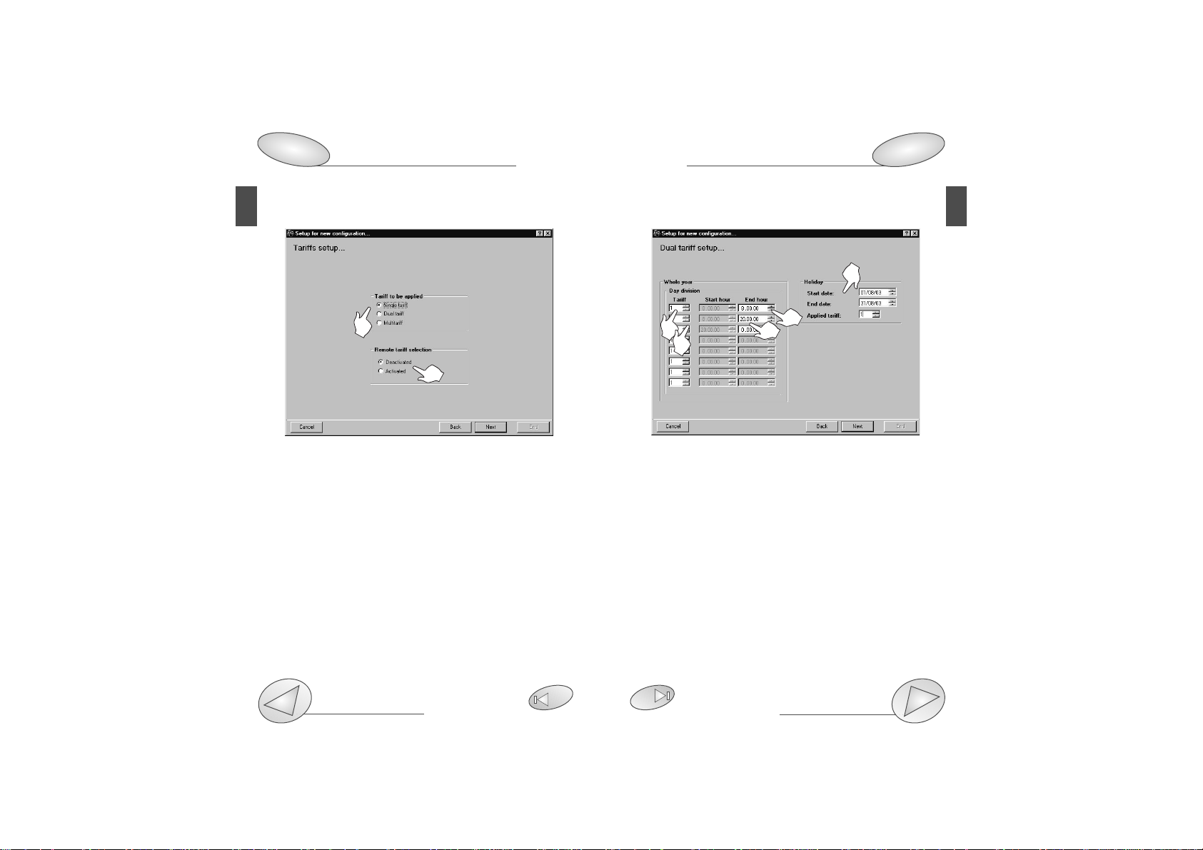
❑Dual tariff setup
[1] Select the reference tariff.
[2] Select the Start Hour and the End Hour of the time peri-
od. The Start Hour of the following tariff is automatically displayed in the gray box of the second tariff.
[3] Select the tariff of reference.
[4] Select the End Hour of the second tariff. Proceed in the
same way until the required number of tariffs is reached.
[5] Programme the Holiday period: set the start date and the
end date and the relevant applied tariff.
PQTSoft Remote
Configuration
29
19
PQTSoft Remote
18
Configuration
8
❑Tariffs and installed power setup
This function allows the user to choose the type of management of the energy meters.
[1] Selects the type of tariff to be applied. “Single tariff”: the
energy meters are set according to a single tariff which is the
same for the whole year. “Dual tariff”: the energy meters are
set with 4 different tariffs per day and two time periods per
year (whole year/holidays). “Multitariff”: the energy meters
are set with up to eight time periods per day (4 different tariffs) and three time periods per year (winter, summer and
holidays).
[2] Selects if the remote tariff selection by means of digital
inputs is to be activated or deactivated. It can be activated
only if the digital input modules are inserted in slot A and C.
1
2
1
2
5
3
4
Page 12
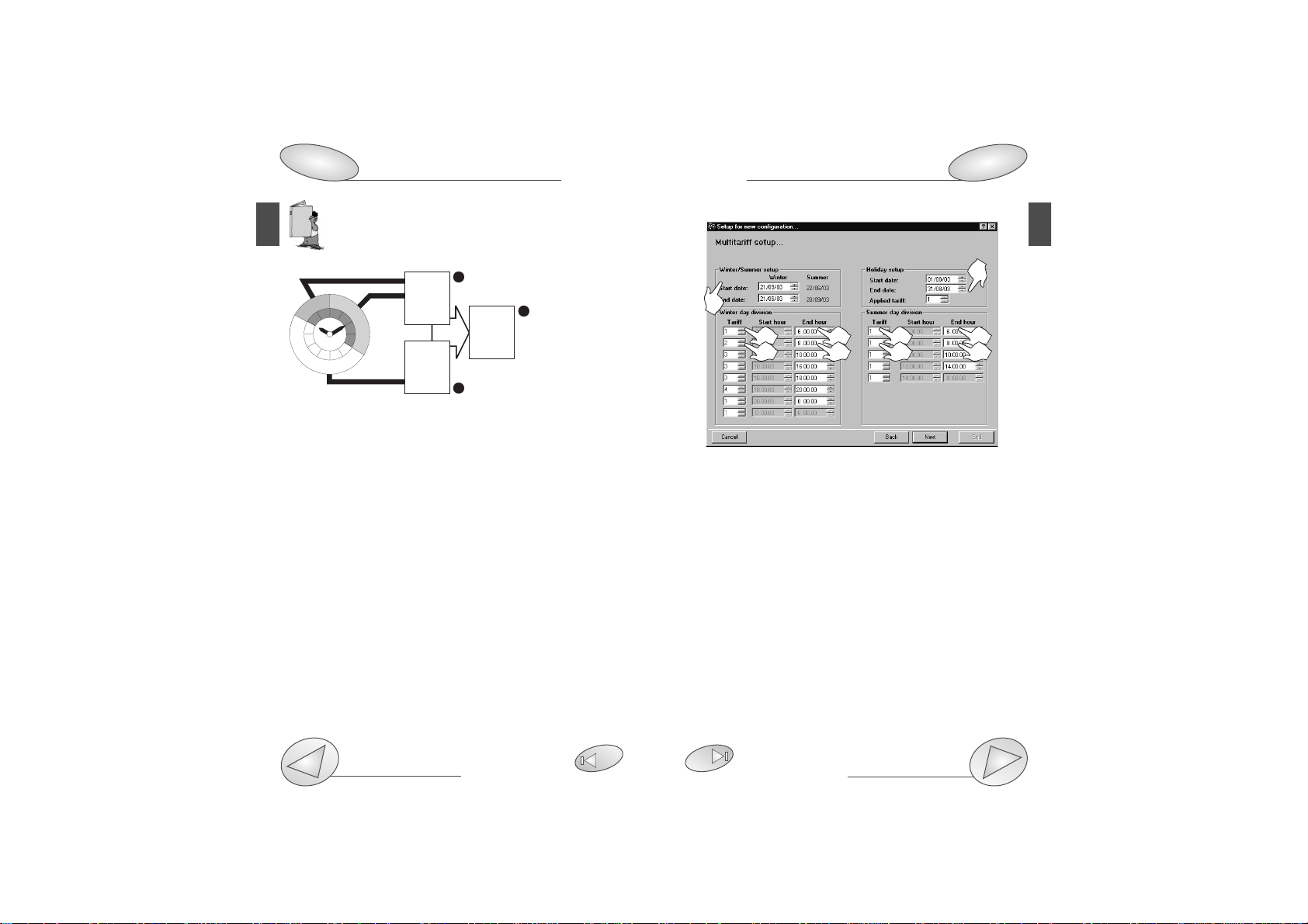
a) It’s possible to divide the day into up to eight
daily different time periods and up to four different
tariffs as shown below:
❑Multitariff setup
[1] Select the duration time of the winter and summer time
period, enter the start date and the end date of the winter
time period. The Summer time period will be calculated
automatically as a consequence.
[2] Select the reference tariff.
[3] Select the End Hour of the time period. The Start Hour of
the following tariff is automatically displayed in the gray box
of the second tariff.
[4] Select the reference tariff.
[5] Select the End Hour of the second tariff. Proceed in the
same way until the required number of tariffs is reached.
[6] Programme the Holiday period: set the start date and the
end date and the relevant applied tariff.
PQTSoft Remote
Configuration
29
21
PQTSoft Remote
20
Configuration
8
The measured energy (partial energy) is placed in TARIFF 1
when the time period is from midnight to 8:00, in TARIFF 2
when the time period is from 8:00 a.m. to 8:00 p.m. and
again in TARIFF 1 when the time period is from 08:00 p.m.
to midnight.
The total measured energy is the result of the sum of all the
partial measures as shown in the figure below:
b) the starting point of the first time period is always 24:00
(midnight) and cannot be changed;
c) the starting point of the following period is always the end
hour of the previous time period.
d) the daily loop is closed by setting 24:00 as last hour of the last
time period.
3
6
5
1
3
5
2
4
2
4
trf1
22
20
18
16
+ kWh
trf1
- kWh
+ kvarh
- kvarh
+ kWh
- kWh
+ kvarh
- kvarh
24
2
4
6
14
8
10
12
trf2
1
+ kWh
- kWh
+ kvarh
- kvarh
2
T
Page 13
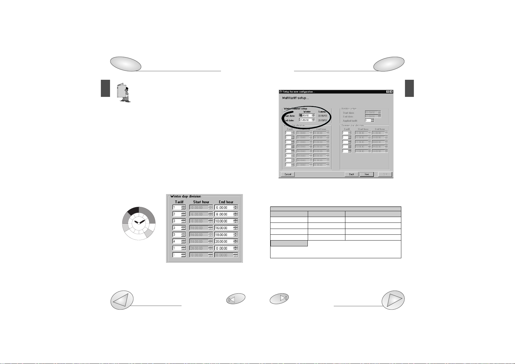
❑Multitariff setup with digital inputs
If “remote tariff selection: activated” has been selected,
then only the “Start date” and “End date” of the winter/summer period need to be saved, as circled above.
PQTSoft Remote
Configuration
29
23
PQTSoft Remote
22
Configuration
Digital input working mode setup
8
12
The WINTER and SUMMER time periods are conventional seasons mainly used to manage in the
best way the different energy costs during the year.
The reminds at steps a), b), c) d) on page 20 are
also valid for the MULTI TARIFF function.
In the SINGLE TARIFF, only one period exists, referred to the
whole year.
In the DUAL TARIFF, the “year” can be divided into two periods: whole year and holidays.
In the multitariff, the “year” can be divided into 3 periods:
winter, summer and holidays.
HOW THE REMOTE TARIFF SELECTION IS CARRIED OUT
C
HANNEL 3 SLOT ACHANNEL 3 SLOT CACTION
Open Open Tariff 4
Open Close 2 Winter / 3 Summer *
Close Open 1 Winter / 2 Summer **
Close Close Tariff 4
CHANNEL 2 SLOT A (if A2 is activated as GAS): If it is closed, the
day GAS tariff is selected, if it is open, the night GAS tariff is
selected.
* PQT-90 applies tariff 2 in the winter period and tariff 3 in the
summer period.
** PQT-90 applies tariff 1 in the winter period and tariff 2 in the
summer period.
Example of winter day division:
On the picture below four different tariffs are shown which
are coupled to seven different periods of the day.
trf
Fine
Inizio
INVERNO
1 OO:OO
O6:OO
2 O6:OO
O8:OO
3 O8:OO
1O:OO
TARIFFA
1
trf
INVERNO
2 1O:OO
16:OO
3 16:OO
18:OO
4 18:OO
21:OO
TARIFFA
2
1 21:OO
OO:OO
Inizio
Fine
trf1
22
trf4
20
18
trf3
16
14
trf2 trf3
24
12
trf1
2
4
6
trf2
8
10
Page 14
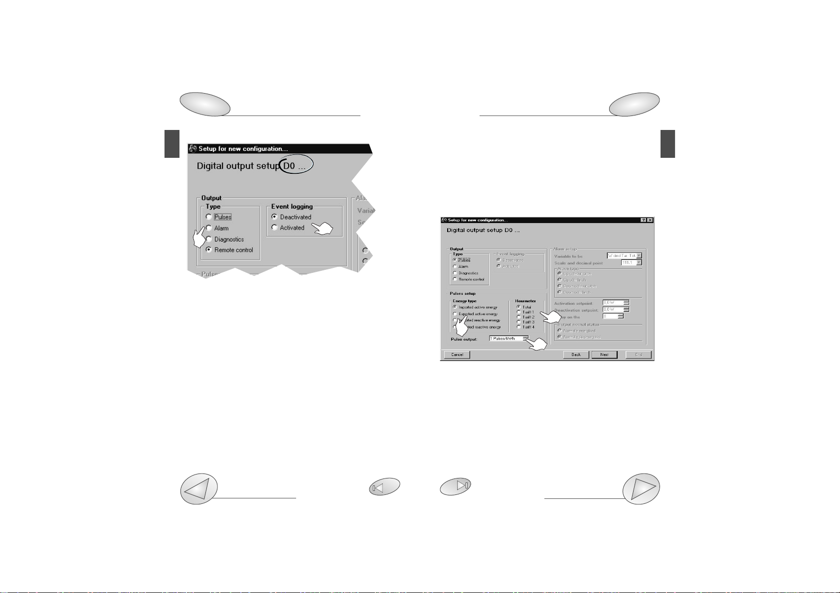
❑Digital output setup
Where “DO...” shows the module and output to which the
window refers. Digital outputs are referred to as follows:
C0 OUTPUT: SLOT C digital output, channel 1
C1 OUTPUT: SLOT C digital output, channel 2
D0 OUTPUT: SLOT D digital output, channel 3
D1 OUTPUT: SLOT D digital output, channel 4
[1] Select the digital output mode:
“Pulses”: sets the parameters for the pulse output. It’s possi-
ble to retransmit the total or partial energy by means of pulses. Selecting one of the available tariffs (from 1 to 4), the pulse
output will be activated only when metering the energy referred
to the selected tariff.
“Alarm”: allows the user to activate a static or a relay output when an alarm condition is detected.
“Diagnostics”: in a 3-phase system, unbalanced load with
neutral, this function checks the presence of the neutral
connection. If the connection to the neutral is not detected,
an alarm is activated.
PQTSoft Remote
Configuration
Open collector outputs
29
46
25
PQTSoft Remote
24
Configuration
8
1
“Remote control”: makes it possible to control the digital
outputs by means of the RS485/RS232 serial port instead of
using the instrument. The outputs can be activated by
means of a PC or PLC by means of specific commands.
[2] Selects whether the event logging in the PQT-90 is to be
activated or deactivated.
❑Digital output setup: pulses
[1] Chooses the type of energy to be retransmitted by
means of pulses.
[2] Selects the type of meter to be retransmitted by means
of pulses.
[3] Selects the pulses amount (that is: how many pulses are
needed for 1 kWh from 1 to 1000 pulses per kWh?).
2
1
3
2
Page 15

❑Digital output alarm setup
[1] Selects the alarm working mode for the digital output.
[2] Selection of activation or deactivation of the event log-
ging of PQT-90.
[3] Selects the variable to be checked. Click the pointer of the
“Variable to be (controlled)” drop-down menu.
Selects the scale and decimal point. Click the pointer of
the “Scale and decimal point” drop-down menu.
[4] Selects the alarm type: selecting the “up-alarm” the alarm is
activated when the selected variable increases above the activation set-point; “Down alarm” the alarm is activated when the
selected variable decreases below the activation set-point.
[5] Activation setpoint: the alarm is activated when the variable increases above this value.
Deactivation setpoint: the alarm is deactivated when the
variable decreases below this value.
Delay on the activation: selects the minimum delay of the
event on the alarm activation.
[6] Chooses the normal status of the output.
Normally energized: the output is normally
PQTSoft Remote
Configuration
Digital output connections
29
47
27
PQTSoft Remote
26
Configuration
8
4
2
3
1
5
6
energized and it’s de-energized in case of alarm.
Normally de-energized: the output is normally de-energized and it’s energized in case of alarm.
❑Analogue output alarm setup
Where “BO...” shows the module and output to which the
window refers. Analogue outputs are referred to as follows:
A0 OUTPUT: analogue output 1, SLOT A
A1 OUTPUT: analogue output 2, SLOT A
B0 OUTPUT: analogue output 3, SLOT B
B1 OUTPUT: analogue output 4, SLOT B
[1] Selects the variable to be retransmitted: click the
pointer of the “Variable” drop-down menu. Click the
pointer of the “Scale and decimal point position”
drop-down menu to select the scale and decimal point.
[2] “Max input value”: selects the max. value of the variable
input range. “Min. input value”: selects the min value of the
variable input range. [3] “Max output value”: value expressed
as % of the full scale value (0-20mA, 0-10V, etc.) that is gen-
1
2
3
Page 16

PQTSoft Remote
28
Configuration
8
Configuration
Useful Information
29
58
29
PQTSoft Remote
erated by the measured value (“max. input value”). “Min. output value”: value expressed as % of the zero of the output
range (0-20mA, 0-10V, etc.) that is generated by the minimum
measured value (“min. input value”).
Example 1: to measure a consumed power up to 100kW
and retransmit it with a signal from 4 to 20mA, the
module to be used is AO1026 (2x from 0 to 20 mA)
or AO1050 (1x from 0 to 20mA); the instrument is to
be set-up as follows:
• Variable: WΣ (active system power)
• max. input value: 100.0 kW;
• min. input value: 0.0 kW;
• max output value: 100.0% corresponds to 20mA, then:
(100*max. output)/fullscale output=100*20mA/20mA =100%
• Min. output value: 20.0% corresponds to 4mA, resulting from:
(100* min. output) / fullscale output= 100*4mA/20mA= 20%
Example 2: to measure both the consumed power (up to
100KW) and the generated power (up to -100kW), and
retransmit it with a signal from -10 to +10V, the module to be
used is AO1033 (2x ±10VDC) or AO1057 (1x ±10VDC). The
parameters can be setup as follows:
• Variable: WΣ (system active power)
• Max. input value: 100.0 kW;
• Min. input value: -100kW;
• Max. output value: 100.0% corresponds to 10V, then:
(100*max. output)/ fullscale output = 100*20V/20V=100%.
• Min. output value: 0.0% corresponds to -10V, then: (100*
min. output)/fullscale output= 100* 0V/20V= 0%; in this case
also the “total” excursion of the analogue output is to be
considered, therefore from -10V to +10V=20V
As a consequence, when the power is -100kW, the output
will be -10V, when the power is 0, the output will be 0V and
when the power is 100kW the output will be +10V.
Example 3: the whole range of the values admitted for the
variable PF corresponds to values between C 0.00 and L
0.00 (for each phase) which, after retransmission, will be
respectively 0 and 20mA. When PF is equal to 1 (since it is
in the middle of C 0.00 and L 0.00), the output will be equal
to the centre of its scale, that is 10mA. As a consequence,
the instrument is to be setup as follows:
• Variable: PF L1 (or L2 or L3);
• Max. input value: L 0.001: the max input value will correspond to
C if its sign is negative and to L if its sign is positive.
• Min. input value: C 0.000; the min input value will correspond to
C if its sign is negative and to L if its sign is positive.
• Max output value: 100%;
• Min. output value: 0.0%
The min. input value to be set for L is 0.001 to avoid any undesired variations of the analogue outputs.
Page 17

❑ Set SMS messagges and telephone numbers
If the “AR1041 module with GSM modem for SMS (Master)”
in the window “Instrument composition...” has been selected, the above window will appear to enable the setup of the
SMS alarm messages to be sent to the phone numbers
typed in the relevant list.
[1] Select which alarms or events are activated to send SMS
messages.
[2] Select a 3-digit password for the identification of PQT-90
when an SMS is received or some information are requested (see “useful information” on page 56).
[3] List of line phone numbers for SMS: type the phone
numbers to which the messages are to be sent.
[4] SMS messages for alarm activation: type the messages
to be sent when the alarms are activated (there’s a max.
number of characters available terminated which the user
will not be allowed to continue typing the message).
Configuration
How to use SMS messages
32
56
31
PQTSoft RemotePQTSoft Remote
30
Configuration
8
[5] SMS messages for alarm deactivation: type the messages to be sent when the alarms are deactivated (there’s a
max. number of characters available terminated which the
user will not be allowed to continue typing the message). In
any case, the user who will receive the message on his
mobile phone will be able to read not only the preset text,
but also date and hour relating to the event.
Max. 5 GSM phone numbers can be typed; the
instrument will send the same SMS activation
and/or deactivation message to all the listed numbers.
3 4
1
2
5
Page 18

❑Communication setup
[1] Choose the mode and connection type (see also
“PQTSoft remote” on page 6). If “Local network of instruments (RS485)” has been selected, then also the network
address of the PQT-90 with which the communication will
take place is to be indicated (see figure above).
[2] Only if “Local single instrument (RS232)” or “Local network of instruments (RS485)” have been selected, the serial
communication port of the PC can also be selected.
❑End of the configuration
After the configuration of all the
PQT-90 parameters, press the
key “End”. The new configuration will be added to the list of
the configurations archive where
you can select it and transmit it
to the instrument.
❑Transmit the configuration
[1] Modify the configuration selected in the list.
[2] Delete the configuration selected in the list.
[3] Transmit the configuration selected in the list.
PQTSoft Remote
Transmission of configuration
Application bar: meaning of the icon
35
56
33
PQTSoft Remote
32
Transmission of configuration
Mode and connection type
8
6
1
3
2
1
2
Page 19

❑Network address and warning messages
[1] Selects whether to “carry out the operation on a single instrument” in the (local or remote) network, therefore the address of
the selected instrument [2] will have to be indicated, or to “carry
out the same operation on all the instrument located on the
(local or remote) network”
[3] End the “communication setup” procedure, starting the
transmission of the configuration to the PQT-90.
■ Reading of instantaneous variables
It allows the reading of all the variables in real time divided
into two pages: one dedicated to the instantaneous
variables and one dedicated to the meters.
After clicking the function button on the main menu
bar, set the communication type, as explained from page 33,
then click on the “end” button [3].
❑Selection of phone numbers and setting of dialling
properties
If in the “Communication setup” dialog box the option
“modem” has been selected, then also the telephone number to be dialled by PQTSoft for the modem connection with
the instrument will have to be selected.
[1] Click the contact to select it. The phone number of the
contact will be shown in the “number to be dialled” box
below the list.
The window for the selection of the contacts will be shown
only in the case of “modem” selection in the
“Communication setup” dialog box.
[2] For further information on the contact selection and
dialling properties see pages 37 to 39.
PQTSoft Remote
Transmission of configuration
Reading of instantaneous variables
82
35
PQTSoft Remote
34
Transmission of configuration
33
1
2
1
2
3
Page 20

❑Selection of connections and setting of dialling properties
This function allows the selection of the list of contacts: create
new contacts, modify them or remove them from the list, simply
clicking on the relevant buttons.
[1] Enter a new contact in the list.
[2] Modify the data of a selected contact.
[3] Delete a selected contact.
[4] Select in detail the dialling properties and decide
whether to use them or not when dialling the telephone
numbers (see dialling properties on the following page).
The defined dialling properties relate to all telephone
numbers present in the list. You can also decide not to
use the above defined dialling properties by not ticking
the relevant check box.
■ Reset of partial and total meters
Reset all the energy, water and gas total and partial meters.
After clicking on the function button on the main menu bar,
set the type of communication, as explained from page 33.
At the following window:
[1] Select if the reset command is to be carried out for all the
instruments located on the network or only on a single
instrument.
[2] Select the network address corresponding to the
required PQT. [3] Carry out the reset.
Steps 1 and 2 are active only for network instruments.
PQTSoft Remote
Last functions
39
37
PQTSoft Remote
36
Last functions
1
2
3
4
■Automatic modem configuration
It allows the automatic configuration of the analog-
ic/GSM modem for the best communication with
PQT-90. Follow the instructions given in the window, then verify that the connections between
modem and PC are correct, finally press the “OK” button.
1
2
3
Page 21

[1] List the currently selected locations. To select a new
location, click on “New...”.
[2] Specify the area code, type it in the box on the right (.e.g.
0039 for Italy)
[3] In the first box write the number/s to be dialled to access
to an external line for local calls (e.g. 0 or 9). In the second
box write the number/s to be dialled to access to an external line for trunk (long distance) calls (e.g. 8). If no additional numbers are needed to make an external call, then leave
these boxes empty.
[4] Specify the dialling type to be used. Select the pulse dial
only if it is the only one available.
[5] If selected, the “calling card” will be used every time you
call from this location (specified in the box “I am dialling
from”) and with any software installed in the PC.
[1] Type the name of the contact
[2] Type the telephone number of the contact
[3] Type the name of the data file folder (where all the files of data
downloaded from the instrument will be saved)
[4] Type the number of PQT located on the network.
[5] If selected, PQTSoft will dial this contact when the “auto-
matic reading” working mode will be active.
❑Dialling properties
PQTSoft Remote
Last functions
39
PQTSoft Remote
38
Last functions
36
1
2
3
4
1
2
3
4
5
5
Page 22

PQT-90 Instruction manual
Installation
Available modules
52
42
41
PQT-90 Instruction manual
40
Installation
4 The last module to be
placed will be the central
module whose function is
to lock all other modules.
2
■ Preliminary Operations
1
1 Release the central module
levering on the fixing tabs by
means of a screwdriver.
2 First extract the central dummy module
and then all other modules.
3 Extract the dummy modules and replace them with
the desired plug and play
modules.
Make sure that the supplied modules are
placed in the correct slots as shown on the
labels placed on the modules and as
described on the following pages. A wrong
insertion of the modules may damage the instrument.
When inserting and extracting the plug and play modules, make sure that the instrument is not connected to
the power supply and that the measuring inputs are not
connected.
Before powering the instrument, make sure that the
power supply voltage correspond to the values on the
label of the power supply module.
■ Overall dimensions and DIN-rail mounting
3
90mm
138mm
Page 23

PQT-90 Instruction manual
Installation
Optional modules connection
52
45
43
PQT-90 Instruction manual
42
Installation
40
DESCRIPTION A B C D PU PS IM
Single analogue output ✓
Dual analogue output ✓✓
RS485 serial output ✓
RS232 serial output ✓
Single relay output ✓✓
Open collector single output ✓✓
Dual relay output ✓✓
Dual open collector output ✓✓
Quadruple open collector output ✓
3 digital inputs ✓
3 digital inputs + AUX ✓✓
Power supply ✓
Inputs ✓
■Position of the slots and relevant modules
■Available modules
❑Analogue output modules
❑Digital output open collector modules
A
B
C
D
PU
PS
IM
AO1058
Single relay
output
AO1035
Dual relay
output
AO1059
Single open
collector
output
AO1036
Dual open
collector
output
Single analogue output
AO1050 (20mADC)
AO1051 (10VDC)
AO1052 (±5mADC)
AO1053 (±10mADC)
AO1054 (±20mADC)
AO1055 (±1VDC)
AO1056 (±5VDC)
AO1057 (±10VDC)
Dual analogue output
AO1026 (20mADC)
AO1027 (10VDC)
AO1028 (±5mADC)
AO1029 (±10mADC)
AO1030 (±20mADC)
AO1031 (±1VDC)
AO1032 (±5VDC)
AO1033 (±10VDC)
Page 24

PQT-90 Instruction manual
Installation
Electrical connections
52
49
45
PQT-90 Instruction manual
44
Installation
Modules position
40
42
AQ1038
3 digital
inputs
AQ1042
3 digital inputs +
aux
AR1034
RS485
Interface
AP1020
90-260 VAC/DC Power supply
AP1021
18-60VAC/DC Power supply
Connection by
means of NPN
transistor.
AQ1042
Digital inputs module.
Connection by
contacts.
Digital inputs module AQ1042.
Connection by
contacts.
Digital inputs module AQ1038.
Connection by
means of PNP
transistor.
AQ1042
Digital inputs module.
❑Digital input modules
❑Serial output modules
❑Power supply modules
■Optional modules connections
❑ Digital inputs
AR1041
RS232 Interface + RTC+ 2Mb
Data Memory
Page 25

PQT-90 Instruction manual
Installation
Output modules specifications
52
61
47
PQT-90 Instruction manual
46
Installation
40
This diagram is valid also
for the single output open
collector module.
The value of the load
resistances (Rc) must be
chosen so that the short
circuit current is lower
than 100 mA; the VDC
voltage must be lower
than or equal to 30VDC.
❑Relay outputs
❑Open collector outputs
AO1058 Single relay
outputs.
AO1035 Dual relay
outputs.
AO1059 open collector single
output.
AO1036 open collector dual
output.
1 analogue output (mA)
1 analogue output (V)
2 analogue outputs (mA)
2 analogue outputs (V)
❑Analogue outputs
Page 26

PQT-90 Instruction manual
Installation
Input features
52
59
49
PQT-90 Instruction manual
48
Installation
Optional modules connections
40
45
❑RS485/422 (AR1034) Serial port
4-wire connection. Additional devices provided with
RS485/422 (that is RS 1,2,3,...N) are connected in parallel.
2-wire connection. Additional devices provided with
RS485/422 (that is RS 1,2,3,...N) are connected in parallel.
The termination of the serial output is carried out
only on the last instrument of the network, by
means of a jumper between (Rx+) and (T). We recommend you to use the 4-wire connection: by
means of the serial port the data are exchanged
faster.
■Electrical diagrams
❑Three-phase, 3/4 wires, Balanced load
Direct connection
(3-wire system)
CT connection
(3-wire system)
CT and VT connection
(3-wire system)
Direct connection
(4-wire system)
Page 27

PQT-90 Instruction manual
58
51
Installation
❑ Three-phase, 4-wire connection, balanced Load
❑Three-phase, 4-wire connection, unbalanced load
CT connection
(4-wire system)
CT connection
(4-wire system)
Direct connection
(4-wire system)
CT and VT connection
(4-wire system)
PQT-90 Instruction manual
50
40
Installation
ARON CT connection
(3-wire system)
ARON CT and VT connection (3-wire system)
❑Three-phase, 3/4 wire connection, unbalanced load
❑ARON connection, Three-phase, 3 wires, Unbalanced load
CT and VT connection
(4-wire system)
CT and VT connection
(3-wire system)
Page 28

PQT-90 Instruction manual
Useful info
Data logging duration
58
54
53
PQT-90 Instruction manual
52
Installation
40
Direct connection
CT and VT connection
CT connection
❑3-phase, 3-wire conn.
❑Single phase connect.
❑Single-phase connection
3 CT and 3 VT connection
(3-wire system)
■Data logging operating principle and duration
The data logging duration depends on the number of variables
that you want to log (from 1 to 8), from the selected integration
time (from 1 to 60 minutes) and from the activation, if any, of
the max./min. logging for each time interval. The following
table simplifies the duration of the data logging according to
the selections. The datum logged in the selected time interval
(tias shown in the graph below) results from the continuous
average of the measured values (samples). The average value
is calculated with an interval of approx. 200 ms between two
subsequent measurements (samples); as a result, the historical data value will be extremely accurate.
t
i
t
i
t
i
Average value of
the “n” sample
ti= time interval (programmable from 1 to 60 minutes)
Average value of the
“n+1” sample
Average value of the
“n+2” sample
Max “n”
Min “n”
Max “n+1”
Min “n+1”
Max “n+2”
Min “n+2”
Page 29

PQT-90 Instruction manual
Useful info
58
55
PQT-90 Instruction manual
54
Useful info
Data Logging Principle
53
53
4 Sel. variables
Data logging duration
D
AYS
WEEKS YEARS
81 12 407 58 1.1
814 116 2.2
- 174 3.4
- 232 4.5
- 291 5.6
- 349 6.7
- 407 7.8
- 465 8.9
- 523 10.1
- 581 11.2
- 639 12.3
- 697 13.4
43 6 215 31 431 62 1.2
646 92 1.8
861 123 2.4
- 154 3
- 185 3.5
- 246 4.7
- 308 5.9
- 369 7.1
Avg
values
6 Selected variables
Data logging duration
D
AYS
WEEKS YEARS
61 9 305 44 610 87 1.7
915 131 2.5
- 174 3.4
- 218 4.2
- 262 5
- 305 5.9
- 349 6.7
- 392 7.5
- 436 8.4
- 479 9.2
- 523 10.1
31 4 153 22 305 44 458 65 1.3
610 87 1.7
763 109 2.1
915 131 2.5
- 174 3.4
- 218 4.2
- 262 5
8 Selected variables
Data logging duration
D
AYS
WEEKS YEARS
49 7 244 35 488 70 1.3
732 105 2
976 139 2.7
- 174 3.4
- 209 4
- 244 4.7
- 279 5.4
- 314 6
- 349 6.7
- 384 7.4
- 418 8
24 3 118 17 236 34 354 51 1
472 67 1.3
591 84 1.6
709 101 1.9
945 135 2.6
- 169 3.2
- 202 3.9
Time
intervals
(min.)
1
5
10
15
20
25
30
35
40
45
50
55
60
1
5
10
15
20
25
30
40
50
60
2 Sel. variables
Data logging duration
D
AYS
WEEKS YEARS
122 17 610 87 1.7
- 174 3.4
- 262 5.0
- 349 6.7
- 436 8.4
- 523 10.1
- 610 11.7
- 697 13.4
- 785 15.1
- 872 16.8
- 959 18.4
- - 20.1
73 10 365 52 1
732 104 2
- 156 3
- 208 4
- 262 5
- 314 6
- 418 8
- 523 10.1
- 628 12.1
Avg+Min+Max Values
Page 30

PQT-90 Instruction manual
Useful info
Setting of SMS messages
58
57
PQT-90 Instruction manual
56
Useful info
Setting of SMS messages
53
30
■Application bar: meaning of the icon
When the PC is going to start the connection with the
remote instrument, one icon appears on the application bar [1]
indicating the status of the connection.
[1] Represents a modem where two “green LEDs” flash
alternately during RX and TX between a PC and a PQT.
■How to use SMS messages
Once the instrument is enabled to send and receive SMS
messages, the user may ask the instantaneous variables, the
last available variables in the data logging, the energy meters
and the alarm status. The table on next page identifies the
codes to be entered in the mobile phone in order to obtain
the desired information.
Generic message to be sent to the instrument: “PQT. [instru-
ment’s password]. [code of required information]”; then confirm the message and send it (follow the instructions given
by your mobile phone).
“xxx”: access password to read the variables via SMS messages. “Log1...Log8”: last integrated variables stored in the
flash memory (variables can be read only after programming
them and enabling them).
Example: in order to ask information on the dmd variables,
enter the following text: PQT.255.DMD; the reply will be:
PQT.255: 12.45KWdmd, 16.04KVA dmd, 3.45kvar dmd,
0.79PF avg (where 255 is the password preset in the instrument).
REQUIRED QUESTION REPLY
INFORMATION CODE
VL1, VL2, VL3, V
L-NΣ
PQT.xxx.VN PQT.xxx:[info]
V
L1-2
, V
L2-3
, V
L3-1
,
V
LΣ
PQT.xxx.VL PQT.xxx:[info]
AL1, AL2, AL3, A
n
PQT.xxx.A PQT.xxx:[info]
WL1, WL2, WL3, W
Σ
PQT.xxx.W PQT.xxx:[info]
VA
L1
,
VAL2, VAL3, VA
Σ
PQT.xxx.VA PQT.xxx:[info]
varL1, varL2, varL3, var
Σ
PQT.xxx.VAR PQT.xxx:[info]
PFL1, PFL2, PFL3, PF
Σ
PQT.xxx.PF PQT.xxx:[info]
W
dmd
, VA
dmd
, var
dmd
, PF
avg
PQT.xxx.DMD PQT.xxx:[info]
Log1, Log2, Log3, Log4, PQT.xxx.LOG PQT.xxx:[info]
Log5, Log6, Log7, Log8
Total kWh+, kvarh+, PQT.xxx.TOTAL PQ T.xxx:[info]
kWh-, kvarhWinter kWh+, kvarh+, PQT.xxx. PQ T.xxx:[info]
kWh-, kvarh- WINTER
Summer kWh+, kvarh+, PQT.xxx. PQT.xxx:[info]
kWh-, kvarh- SUMMER
Holidays kWh+, kvarh+, PQT.xxx. PQ T.xxx:[info]
kWh-, kvarh- HOLIDAY
Alarm status PQT.xxx. PQT.xxx:[info]
ALARM
1
Page 31

PQT-90 Instruction manual
Technical features
Output specifications
67
61
59
PQT-90 Instruction manual
58
Useful info
53
The variables measured by the instrument are correct if the inputs have been connected according
to the right polarities (see figure below). Should the
connection not be conforming to the right polarities, measuring and retransmission errors may occur, both
due to the wrong direction of the current flowing in the primary/secondary of the ammeter transformer being connected.
■What is ASY
The ASY variable allows you to control the asymmetry of
the delta voltages (for systems without neutrals) and star
voltages (for systems with neutral). The variable is calculated as follows:
where the first formula is to be applied to delta systems,
while the minimum value calculated between the two is to
be used for the star systems.
■ Input specifications
Number of analogue inputs
Current:
1 (1-phase; system code: 3)
3 (3-phase; system code: 3)
Voltage:
1 (1-phase; system code: 3)
4 (3-phase; system code: 3)
Digital inputs
AQ1038 No. of inputs: 3 (voltage-free). Purpose: W
dmd
measure-
ment synchronisation + var
dmd
and PF
dmd
. Interfacing with watt-
hour meters (+kWh, +kvarh)
.
Tariff selection: energy.
Contact
measuring current:
<8mA/ 17.5 to 25VDC
AQ1042
No. of inputs: 3 + excitation output
Purpose: W
dmd
measurement synchronisation + var
dmd
,
PF
dmd
. Interfacing with watt-hour meters (-kWh, -kvarh) and/or
measurements of gas /water m3.
Tariff selection: energy or GAS.
Excitation output: 16V<+Aux<24VDC Max 15mA.
Contact measuring current:
15mA.
Common characteristics: Input frequency: Max 20 Hz, duty
cycle 50%. Close contact resistance: ≤1kΩ. Open contact
resistance: ≥100kΩ. Insulation: 4000V
RMS
Max input number:
6 in the configuration:
AQ1038+AQ1042 or 2*AQ1042
Accuracy
(RS232, RS485) In: 5A, If.s.: 6A, Un: 240VL-N, Vf.s.: 300VL-N.
Current (@25°C ±5°C, R.H. ≤60%, A
L1
, AL2, AL3) ±0,5% RDG (0.2
to 1.2 In), ±5mA (0.02 to 0.2 In). Current (An) @ 40 to 100Hz ±1%
RDG (0.02 to 1.2 In). Voltage (@25°C ±5°C, R.H. ≤60%) range AV5:
±0.5% RDG (from 48 to 300 V
L-N
) ±1% RDG (from 84 to 519 V
L-
L
); range AV7: ±0.5% RDG (from 80 to 480 V
L-N
) ±1% RDG (from
139 to 830 V
L-L
) includes also: frequency, power supply and out-
put load influences. Frequency: ±0.1% RDG
(40 to 440 Hz).
Active power (@ 25°C ± 5°C, R.H. ≤ 60%):
±0.5% (RDG + FS) (PF 0.5 L/C, 0.1 to 1.2 In, range AV5) or
±1% RDG (PF 0.5 L/C, 0.1 to 1.2 In, range AV5)
Reactive power (@ 25°C ± 5°C, R.H. ≤ 60%):
Page 32

PQT-90 Instruction manual
Technical features
67
61
PQT-90 Instruction manual
60
Technical features
59
Continuous: voltage/current: AV5: 300V
L-N
/ 500V
L-L
/ 6A
AV7: 480V
L-N
/ 830V
L-L
/ 6A
For 1s: voltage/current: AV5: 600V
L-N
/1040V
L-L
/120A
AV7: 960V
L-N
/1660V
L-L
/120A
■ Output specifications
Analogue outputs (on request)
Number of outputs: up to 4
Accuracy: ±0.2% f.s. (@ 25°C ±5°C, R.H. ≤60%)
Range: 0 to 20 mADC, 0 to ±20 mADC 0 to ±10 mADC,
0 to ±5 mADC 0 to 10 VDC, 0 to ±10 VDC 0 to ±5 VDC,
0 to ±1 VDC
Scaling factor: programmable within the whole range of
retransmission; it allows the retransmission management of
all values from: 0 to 20 mADC, 0 to ±20 mADC, 0 to
±10mADC, 0 to ±5 mADC, 0 to 10 VDC, 0 to ±10 VDC, 0 to
±5 VDC, 0 to ±1 VDC. Variables to be retransmitted: all.
Response time: ≤ 200 ms typical
(filter excluded, FFT excluded).
Ripple:
≤1% according to IEC 60688-1
and EN 60688-1.
Temperature drift: ≤ 200 ppm/°C.
Load: 20 mADC ≤ 600Ω, ±20 mADC ≤550Ω, ±10 mADC
≤1100Ω, ±5 mADC ≤ 2200Ω, 10 VDC ≥10 kΩ, ±10 VDC ≥10kΩ,
±5 VDC ≥ 10kΩ, ±1 VDC ≥10kΩ.
Insulation by means of optocouplers: 4000 V
RMS
output to
measuring input 4000 V
RMS
output to supply input.
RS422/RS485 (on request): bidirectional (static and dynamic
variables). Connections: 2 or 4 wires, max. distance: 1200m,
termination directly on the module.
Addresses: from 1 to 255, software programmable.
Protocol: MODBUS RTU/JBUS. Data format: (bidirectional).
Dynamic (reading only): all variables.
±0.5% (RDG + FS) (PF 0.5 L/C, 0.1 to 1.2 In, range AV5) or
±1% RDG (PF 0.5 L/C, 0.1 to 1.2 In, range AV5)
Apparent power (@ 25°C ± 5°C, R.H. ≤ 60%):
±0.5% (RDG + FS) (0.1 to 1.2 In, range AV5) or ±1% RDG
(0.1 to 1.2 In, range AV5).
Energies (@ 25°C ± 5°C, R.H. ≤ 60%): Active: class 1 accord-
ing to
EN61036. Reactive: class 2 according to EN61268, Ib:
5A, Imax: 6A 0.1Ib: 500mA Start-up current: 20mA Un: 240V
(AV5), 400V (AV7).
Harmonic distortion: 1% FS (FS: 100%) (@ 25°C ± 5°C, R.H.
≤60%) phase: ±2°; Imin: 0.1Arms; Imax: 15Ap; Umin: 50V
RMS
;
Umax: 500Vp.
Sampling frequency 6400
samples/s
@ 50Hz
Additional errors:
Humidity
≤0.3%
RDG
, 60% to90% R.H.
Input frequency: ≤ 0.4% RDG, 62 to 400 Hz.
Magnetic field: ≤ 0.5% RDG @ 400 A/m
NOTE: all accuracies are referred to measurements carried out
with the analogue input module.
Temperature drift:
≤200ppm/°C.
Sampling rate: 6400 samples/s @ 50Hz.
Measurements: current, voltage, power factor, energy, power
factor, frequency, harmonic distortion. TRMS measurement of a
distorted wave. Coupling type: direct. Crest factor: ≤3, max.
15Ap/500Vp AV5 (L-N), 15Ap/800Vp AV7 (L-N)
Ranges (impedances)
AV5: 58/100 V (> 500 kΩ) - 1 AAC (≤ 0.3 VA)
58/100 V (> 500 kΩ) - 5 AAC (≤ 0.3 VA)
240 V/415 V (> 500 kΩ) -1 AAC (≤ 0.3 VA)
240 V/415 V (> 500 kΩ) -5 AAC (≤ 0.3 VA)
AV7: 100/170 V (> 500 kΩ) -1 AAC (≤ 0.3 VA)
100/170 V (> 500 kΩ) - 5 AAC (≤ 0.3 VA)
400/690 V (> 500 kΩ) - 1 AAC (≤ 0.3 VA)
400/690 V (> 500 kΩ) - 5 AAC (≤ 0.3 VA)
Frequency: 40 to 440 Hz
Overload protection:
Page 33

PQT-90 Instruction manual
Technical features
67
63
PQT-90 Instruction manual
62
Technical features
59
(OFF)
according to DIN43864. Insulation by means of opto-
couplers, 4000 V
RMS
output to measuring inputs
4000 V
RMS
output to power supply input. Notes: the outputs can
be either open collector type or relay type (for the relay output refer
to the specifications described in the “alarm outputs” section).
Alarm outputs (on request):
Number of set-points: up to 4, independent
Alarm type: up alarm, down alarm, with or without latch, phase
asymmetry, phase loss, neutral loss.
Monitoring of the variable: all variables.
Set point adjustment: 0 to 100% of the displayed electrical
scale
Hysteresis: 0 to 100% of the electrical scale
On-time delay: 0 to 255 s
Relay status: selectable between normally energized or normally
de-energized. Output type: relay, SPDT AC 1-8A, 250VAC.
DC 12-5A, 24VDC AC 15-2.5A, 250VAC DC 13-2.5A, 24VDC.
Min. response time: ≤ 150 ms, filters excluded, FFT excluded,
set-point on-time delay: ”0s”.
Insulation: 4000 V
RMS
output to measuring input, 4000V
RMS
output to power supply input. Note: the outputs can be either
relay type or open collector type (for the latter one, see the
specifications mentioned in the pulse outputs).
Operating mode selection: direct measurements for the
power quality analysis (LV or MV/HV connection); Indirect energy and power measurements by means of watt-hour meters (LV
or MV/HV connection); direct measurements for the instantaneous variables (LV connection) and indirect measurements for
the energy variables (LV or MV/HV). It’s possible to add the management of gas and water metering to all of these working
modes.
Pulse weight: water/gas meter inputs: selectable from 1 to
10000 pulses/m
3
, energy from 1 to 10000.00 pulses/kWh/kvarh
Static (writing only): all configuration parameters, energy reset,
activation of digital outputs.
Data format: 1 start bit, 8 data bit, no parity/even parity/ odd
parity, 1 stop bit.
Baud rate: 9600 bit/s. Insulation by means of optocouplers,
4000 V
RMS
output to measuring input, 4000 V
RMS
output to
power supply input. RS232 (on request): bidirectional (stat-
ic and dynamic variables). Connections: 3 wires, max. distance: 15m.
Data format: 1 start bit, 8 data bit, no parity, 1 stop bit.
Baud rate: 9600, 38400 bit/s. Protocol: MODBUS RTU
(JBUS). Other features: as per RS422/485.
Communication by modem: analogue modem for the remote
communication of all the data measured and managed by
PQT. External communication modem (recommended type:
US Robotics ); GSM modem for the transmission of SMS messages: alarms, instantaneous variables, last available variables
of data logging (only average values) and energy meters. The
alarm messages are given with the date and the time of the
event. The type and value of the set-point can be put into the
alarm message (max 99 characters). The alarms can also be
transmitted automatically, while the variables can be recalled
by means of special SMS question codes. GSM kit type-tested for PQT: Siemens kit (external) model “TC35 TERMINAL”
included GSM module, antenna and 230V power supply.
Digital outputs (on request): to be used as alarms and/or
retransmission of the energy-gas-water metering and/or outputs remotely controlled by the serial communication port.
The outputs are completely programmable independently of
the type of module being used.
Pulse outputs (on request): number of outputs: up to 4. Type:
open collector, (NPN transistor) V
ON
1.2 VDC/ max. 100mA
V
OFF
30 VDC max,
from 1 to 1000 programmable pulses
for k-
M-G Wh, k-M-G varh.
These outputs can be connected to total
and/or partial meters. Pulse duration:
220 ms (ON), ≥ 220 ms
Page 34

PQT-90 Instruction manual
Technical features
67
65
PQT-90 Instruction manual
64
Technical features
59
■ General Specifications
Operating temperature: 0 to +50°C (32 to 122°F)
(R.H. < 90% non-condensing).
Storage temperature: -10 to +60°C (14 to 140°F)
(R.H. < 90% non-condensing).
Insulation reference voltage: 300 V
RMS to ground (AV5 input)
Insulation: 4000 VRMS between all inputs/outputs to ground.
Dielectric strength: 4000 VRMS
for 1 minute.
Noise rejection: CMRR 100 dB, 48 to 62 Hz.
EMC: EN 50081-2, EN 50082-2.
Other standards: safety IEC 61010-1, EN 61010-1.
Product: Energy Measurements: EN61036, EN61268.
Pulse output: DIN43864.
Approvals: CE, UL, CSA.
Connections: Screw-type. Max. section: 2.5 mm2(2x1.5mm2)
Housing:
Dimensions 90x90x140 mm.
Material: ABS, self-extinguishing: UL 94 V-0.
Front degree protection: IP20.
Weight: approx. 600 g (packing included).
■ Supply specifications
AC/DC voltage: 90 to 260V (standard) 18 to 60V (on
request). Power consumption: ≤ 30VA/12W (90 to 260V),
≤20VA/12W (18 to 60V).
Transformer ratio: up to 6000 (CT up to 30kA).
Up to 6000 (VT up to 600kV).
Filters:
Filter operating range: 0 to 99.9% of the input electrical scale.
Filtering coefficient: 1 to 255
Filter action: display, alarms, serial outputs (fundamental variables: V,A, W and their derived ones).
Event logging: only with RS232+RTC+Data memory. Type of
data: alarms and max./min. (max. 480 events) stored with date
(dd:mm:yy) and hour (hh:mm:ss) reference and data logger.
Sampling management: only for data logger.
The sample stored within the selected time interval results from
the continuous average of the measured values. The average is
calculated (min. sample) with an interval within two following
measurements of approx. 200 ms. The variables (up to 8) can be
stored as average value, minimum and maximum instantaneous
values. Minimum is intended as lowest value among those sampled in the programmed time interval. Maximum is intended as
highest value among those sampled in the programmed time
interval. See table “the working mode of data logging”.
Data management type: FIFO.
Memory size: 2Mbyte.
Battery life: 10 years.
Data logger function: the data are stored at time intervals from
1 to 60 min.; up to 8 instantaneous variables can be selected.
Historical data storing time. Two different data logger
modes can be selected: average calculation within the pro-
grammed time interval and minimum, maximum values and
average calculation in the programmed time interval.
Data format: day, month; time: hour, minutes, seconds;
type of stored variable: variable value.
Page 35

PQT-90 Instruction manual
Technical features
67
PQT-90 Instruction manual
66
Technical features
59
Multi-time: energy.
Number of total meters: 4; partial meters: 48; (kWh+/kvarh+) from
0,00 to 999 999 999.99 (kWh-/kvarh-) from 0,00 to -999 999 999.99
Time periods: 4, programmable within 24 hours.
Time seasons: 3, programmable within 12 months.
Pulse output: to be connected to the total and/or partial meters
(dual time, multi-time periods).
Energy metering recording: Energy consumption history,
recording of energy metering by months, oldest data: 2 months
before current date. Recording of total and partial energy metering. Energy metering recording (/EEPROM). Max.
999 999 999.99
kWh/kvarh.
■ Harmonic distortion analysis
Analysis principle: FFT
Harmonic measurement: current, up to the 50thharmonic
Voltage, up to the 50
th
harmonic.
Type of harmonics:
THD (VL1) THD odd (V
L1) THD even (VL1).
Same is for the other phases: L2, L3.
THD (A
L1) THD odd (AL1) THD even (AL1).
Same is for the other phases: L2, L3.
Harmonic phase angle: the instrument measures the angle
between the single harmonic of “V” and the single harmonic of “I”
of the same order. According to the value of the “electrical angle”
it is possible to know if the distortion is absorbed or generated.
Note: if the system has 3 wires the angle cannot be measured.
Harmonic details: THD % / RMS value; THD even % / RMS value;
THD odd % / RMS value / single harmonics in % / RMS value.
System: the harmonic distortion can be measured in singlephase, 3-wire or 4-wire systems. Tw: 0.02.
■ Time period management (energy, water and
gas metering)
Time periods: energy, selectable: single time, dual time and
multi time.
Single time: energy, water, gas.
Number of meters: 4(kWh+/kvarh+) from 0.00 to
999 999 999.99 (no partial meters) (kWh-/kvarh-) from 0.00 to
-999 999 999.99
Dual time: energy, gas.
Number of total/partial meters: 4 (kWh+/kvarh+) from 0.00 to
999 999 999.99 (kWh-/kvarh-) from 0,00 to -999 999 999.99.
Time periods: 2, programmable within 24 hours.
Page 36

Setup
Main menu
69
72
PQTSoft Network
69
68
Setup
PQTSoft Network
■Installing PQTSoft Network
When the CD-ROM is
inserted in the drive, the
installation software is
automatically executed
(the CD-ROM drive is to be
enabled) and the dialog
box on the left is displayed. If the setup will not
run, select “explore CDROM” and manually execute the application double clicking the icon
.
Then, choose the operating system and the desired language from the drop-down menus (see figure above). Press
“Install” to carry on with the installation following the instructions given in the following dialog boxes.
It is recommended to save all current jobs and close all
open applications before installing the PQTSoft
Network.
■Uninstalling PQTSoft
Select “Uninstall PQTSoft” to start the guided uninstallation
of PQTSoft.
■ The software in brief
The PQTSoft Network has been developed for the data
transfer from the instrument (PQT90) to the PC. The data
download from PQT90 to the PC allows the reading and
saving of the values logged in the 2MB memory of PQT; the
values can be saved as an Excel table.
The PQTSoft Network has been mainly developed to automatically download the values logged in the PQT; it is therefore necessary to configure first of all the “automatic data
download” dialog boxes. The data transfer can be carried
out in various modes: it depends if the PQT is part of a local
or of a remote network of instruments. The figure on the following page shows the possible communication modes
and the correct selection to be made in the PQTSoft
Network.
Page 37

Setup
Communication setup
73
PQTSoft Network
71
70
Setup
68
PQTSoft Network
Local single PQT connected to
the PC by RS232 serial port.
Maximum 255 PQT’s in an RS485 local network connected to
the PC by RS232 thanks to the RS485-RS232 SIU-PC converter.
Max 25,000 PQT’s in max 100 remote RS485 networks
(each made of 250 instruments) connected to the PC by
means of a telephone network and RS485-RS232 SIU-PC
converter.
RS232
RS485RS485
SIU-PC
RS232
... MAX255
RS232 RS232
MODEM
MODEM
Telephone network
... MAX100
RS232 RS232Telephone network RS485
MODEM MODEM SIU-PC
... MAX100
... MAX255
... MAX255
Max. 100 remote single PQT’s (PQTSoft can manage max.
100 phone numbers to be chosen among those listed in the
phone book) connected to the PC by means of a telephone
network thanks to an analogue modem (make sure that the
“nullmodem” connector is always connected between PQT
and modem).
Page 38

Configuration
Manual data-download
83
78
PQTSoft Network
73
72
Configuration
Meaning of the icon
56
PQTSoft Network
■ Configuration of the automatic data download
This function allows the configuration for an automatic reading, at programmable dates, of the data logged in the data
logger of PQT-90 (AR1041). PQTSoft will question the
instrument on the programmed dates.
❑Communication setup
[1] Select the currently used mode and connection type.
Select the data corresponding to the PC configuration.
[2] Choose the serial port to be used.
■ Main menu
1) Drop-down menu of the functions.
2) Enabling automatic control: enables the automatic reading of
the PQT-90 according to the configurations. Once the automatic
reading has been enabled, the main menu disappears; the programme will be working in the background and an icon will appear
in the Windows execution-bar. To delete the automatic download
and restore the main menu, double click the icon in the Windows
application-bar.
3) Configuration of the automatic data download: it allows
the parameter configuration for the automatic download of the
data.
4) Enabling of the manual data download: it allows the user
to manually download the data stored in the memory of PQT-90.
5) Reading of the instantaneous variables: it allows the reading in real time of the instantaneous variables and meters.
6) Configuration of the analogue modem: it allows the automatic configuration of the analogue modem connected to the
instrument.
7) Configuration of GSM modem: it allows the automatic configuration of the GSM modem connected to the instruments.
8) Management of the phone book: it allows the management
of the user names and relevant phone numbers plus telephone
parameters.
9) File conversion into XLS format: it converts the data files of
the PQT-90 into XLS format files which can be opened by
Microsoft Excel.
10) Software status: if any error occurs during the execution,
their description will be displayed.
1
2
1
3
4
5
10
2
6 7 8 9
Page 39

❑ Folder selection for data files, counter file and
event file
[1] Tick the box on the left to select the data to be downloaded from the data logging of the instrument relevant
to the preselected variables and/or the meters and/or
logged events.
[2] It is possible to select the desired directory where the
data are to be saved by means of the relevant “....” button
(see figure above).
[3] For the data relevant to the variables it is possible to
automatically obtain the conversion into XLS format (useful
to display files as Microsoft Excel) by ticking the “automatic
create XLS files” check box.
Once this phase is completed, proceed with the next settings by clicking the “Next” button.
1
1
2
2
2
3
Configuration
PQT/Excel data converter
83
88
PQTSoft Network
75
74
Configuration
Mode and connection type
72
70
PQTSoft Network
1
2
1
❑ Selection of phone numbers and dialling properties
If in the “Communication setup” dialog box the option
“modem” has been selected, then also the telephone number/s to be dialled by PQTSoft for the modem connection
with the PQT/s remote will have to be selected. Type in the
“Data file folder” column the name of the folder where the
data are to be saved and type also the number of instruments related to that telephone number.
[1] Enable the desired contacts by selecting “ON” in the
“Selection” column, as shown in the figure above. The
PQTSoft will dial, one by one, all the enabled phone numbers, downloading the data of each related PQT; should one
of the remote connections not have a positive result (e.g. the
line is engaged), then PQTSoft will pass on to the following
number until the list of the “ON” selected contacts is completed. Any connection error will be shown to the user.
For any further information on the “Selection of phone
numbers and dialling properties”, see on page 87.
Page 40

❑
If “Local network of instruments (RS485)” was selected
If the “Local network of instruments (RS485)” has been
selected in the “communication parameter” setup, in addition to selecting the directory for the files to be saved, [1]
the user also has to enter the number of PQT-90s present in
the network (from 1 to 100) using the arrows in the numeric
box named “Network number of PQT” (Number of PQTs
located on the network). This selection box is only valid for
the selection “Local network of instruments (RS485)”; for the
other selections this box will not be shown.
❑Setting expiry date for automatic data download
[1] Select expiry date for automatic data download
Configuration
83
PQTSoft Network
77
76
Configuration
72
PQTSoft Network
1
1
2
Daily: PQTSoft Network will download the data in the period specified by the “daily expiry date” box. The exact expiry
date is shown in bold letters after “Next expiry date...”.
Weekly: PQTSoft downloads the data once a week. The PC
will download the requested data at 00,00 of the first
Monday following the activation of the measurement; the
next download will be carried out at intervals of one week.
The date and time are shown in bold after “Next expiry
date...”.
Every two weeks: PQT-90 downloads the data every two
weeks. The PC will download the requested data at 00,00 of
the Monday following the date of activation of the measurement. The following download will be carried out at intervals
of two weeks from the previous one. The date and time are
shown in bold after “Next expiry date...”.
Monthly: PQTSoft downloads the data monthly. The PC will
download the requested data at 00,00 of the first day of
each month. The date and time are shown in bold after
“Next expiry date...”.
Tick one of the above check boxes according to your needs.
To complete the setup procedure, press the “End” button.
[2] Before automatic connection with PQT request a
confirm: PQTSoft will ask the user for a confirmation before
connecting to PQT.
[2] If error, disable the automatic control: should PQTSoft
find an error while downloading data, it will disable the following controls.
[2] Activate automatic control at once end this wizard:
PQTSoft will activate automatic control at the end of this
wizard, that is when the “End” button is pressed. In this
case the main menu will disappear, the software will continue working in the background and an icon will appear on the
Windows application-bar.
Page 41

Configuration
83
PQTSoft Network
79
78
Configuration
Automatic data download
72
73
PQTSoft Network
To interrupt the automatic control mode, double click the icon
present on the application bar. To activate the automatic con-
trol in a second time, press the button shown on the
left. The programme will disappear from the PC
screen (it will continue working in the background)
and an icon will appear on the Windows application bar as
shown on the previous page.
■ Manual data download
This function allows the manual download of the data stored
in the 2MB memory (AR1041) of the instrument. The
PQTSoft will question the instrument at the end of the procedure shown below.
❑Communication setup
[1] Select the mode and connection type of your PC.
[2] If you have chosen RS485, specify the number of PQTs
in the network as shown in the figure above. Once this procedure is ended, proceed with the next settings pressing the
“Next” button.
❑ Selection of telephone number and setting of
dialling properties...
If the option “modem” has been selected in the
“Communication Setup” dialog box, then also the telephone
number to be dialled by PQTSoft for the modem connection
with PQT-90 will have to be selected among those available
in the “Contact” list.
[1] Click the contact to select it. To proceed, press the
“Next” button.
[2] For any further information on the contact selection and
dialling properties see page 87.
1
2
1
2
Page 42

❑ Define file name for downloaded data, counter and
event... after selecting “Local network of instruments
(RS485) or remote network”
[1] If you have selected “local or remote network of instruments” in the first page of “Communication setup”, you
have to enter also the address of the PQT (as shown in the
figure above) from which you want to download the data;
carry out this operation using the arrows in the numeric box
named “Network address” (from 1 to 255). For the selections with only one instrument, this box will not be active.
❑Define file name for downloaded data, counter and
event....
[1] Choose the data to download from the instrument
(AR1041 module) ticking the relevant check box: these data
relate to the preselected variables and/or to the meters and
/or events.
[2] It’s possible to select the desired directory where the
data are to be saved by means of the “....” button.
[3] For the data relevant to the variables, it’s possible to
automatically convert the file into XLS format (Microsoft
Excel format) by ticking the relevant check box (“Automatic
create XLS data file”). Once this phase is ended, proceed
with the next settings by pressing the “Next” button.
[4] Ticking the relevant check-box you can choose whether
to delete PQT’s data logging after downloading the data.
[5] Ticking the relevant check-boxes you can choose if, after
reading the events, these data are to be deleted or not. You
can also choose if, after reading the events, the max. and
min. peak values are to be deleted.
Configuration
PQT / Excel data converter
83
88
PQTSoft Network
81
80
Configuration
Data Logging
72
53
PQTSoft Network
1
1
2
2
2
3
1
5
1
4
Page 43

Configuration
83
PQTSoft Network
83
82
Configuration
Mode and connection type
72
71
PQTSoft Network
■ Reading of instantaneous variables
This function allows the reading of all the variables and
meters in real time divided into two pages.
After clicking the “function” button on the main menu’s tool
bar, set the communication type [1] and then the communication port with the PC [2]. Clicking the “end” button, the
relevant dialog box (see below) will be opened.
If you have selected “local network of instruments (RS485),
it is necessary to enter the number of PQTs installed in the
network (see figure on page 82) moving the arrows on the
right of the number up and down.
❑
If “Modem” has been selected in the “Communication
setup”
If you have selected “modem” in the “Communication
setup...” dialog box, the user will have to choose which
telephone number is to be dialled among those in the “con-
tact” list.
[1] Click the contact to select it. To proceed, press the
“Next” button.
[2] For further information on the management of the contacts and the dialling properties see page 87.
1
2
1
2
Page 44

Last functions
88
PQTSoft Network
85
84
Last functions
PQTSoft Network
■ Configuration of analogue modem and GSM
Automatic configuration of analogue modem: it allows
the automatic configuration of the analogue modem. Follow
the instructions given in the dialogue box, then verify that
the connections related to the communication between
modem and PC are ok and finally click the “OK” button.
Automatic configuration of GSM modem: it allows the
automatic configuration of the GSM modem. Follow the
instructions given in the dialog box, then verify that the connections related to the communication between modem and
PC are ok and finally click the “OK” button.
■ Contact management
❑ Selection of connections and setting of dialling properties
This function allows the management of the contact list: cre-
ate new contacts, modify them or delete them from the contact list, easily clicking the related buttons.
[1]: enter a new contact in the list.
[2]: modify the data of the selected contact.
[3]: delete the selected contact.
[4]: Set the dialling properties in detail and decide whether to
use them or not when dialling the phone numbers (see dialling
properties on the following page).
The set properties relate to the dialling of all numbers
present in the list.
1
2
3
4
Page 45

Last functions
88
PQTSoft Network
87
86
Last functions
84
PQTSoft Network
[1] Enter the name of the contact
[2] Enter the telephone number referred to the contact.
[3] Enter the name of the folder where all the files of the data
downloaded by PQT will be saved.
[4] Enter the number of PQTs located on the network.
[5] If selected, PQTSoft will dial this contact when the operating
mode “automatic data download” will be enabled.
[1] Select the location chosen in the dialling properties.
1
2
3
4
5
It is possible to enable or disable the
contacts to be dialled by PQTSoft
also directly on the list clicking the
“Selection” column on the line corresponding to the contact to be
enabled/disabled. A drop-down
menu will appear: double click “On”
to enable or “Off” to disable.
❑ Dialling properties
[1] List the currently selected locations. To select a new
location click “New”.
[2] On the left box select the country from the list of the
drop-down menu, on the right box type the area code (e.g.
0039 for Italy).
[3] In the first box type the number/s to be dialled to access
an external line for local calls (e.g. “0” or “9”). In the second
box type the number/s to be dialled to access an external
line for trunk calls (e.g. “8”). If no number is needed to
access an external line, leave the boxes empty.
1
1
1
2
3
4
5
Page 46

88
Last functions
Data file folders selection
84
75
PQTSoft Network
[4] Specify the dialling type to be used. Choose the pulse
dialling only if it is the only one available.
[5] If it is selected, the phone card will be used every time
the user is calling from this location (specified in the box “I
am dialling from”) and with any software installed in the
computer.
■ PQT-90 data conversion into Excel format
This software is supplied with a converter able to convert the
data file of PQT-90 into XLS (Microsoft Excel) files.
[1] Select the directory of the Source PQT data file to be
converted.
[2] Select the target directory of the converted file. Start the
procedure with “OK” or cancel it with “Cancel”.
1
2
 Loading...