

CARLO GAVAZZI MDI 40 TF - CONFIGURATION SOFTWARE, MDM 40 TF - CONFIGURATION SOFTWARE, MDI 40 TF, MDM 40 TF Instruction Manual
Page 1

Page 2

V
MDM
Digital Meter
al1 al2
RPM
F
S
Page 3

ENGLISH
MDI40.TF Rate meter and
controller
OPERATING INSTRUCTIONS
• General Features 2
• Technical Features 3
• Installation 7
• Preliminary Operations 12
• Front Panel Description 13
• Operating mode 15
Important:
We suggest you keep the original packing for a further
shipping of the instrument.
In order to guarantee a correct use of the instrument, we
recommend the user to carefully read the present instruction manual.
Page 4

3
ENGLISH
2
ENGLISH
•operating mode;
•scaling;
•display;
•commands;
•alarm set-points;
•filter;
•analogue output;
•serial output.
TECHNICAL FEATURES
ACCURACY ± 0.01 % F.S., ± 3 dgt (@ 18°C to 23°C);
RESPONSE TIME Time base + ≤ 200 msec.
TEMPERATURE DRIFT ± 100 ppm/°C.
DISPLAY 7-segment, red LED, h 14.2 mm.
MAXIMUM INDICATIONS 9999.
MINIMUM INDICATIONS -1999.
INPUTS 2 measuring inputs (channel "A" and channel "B"); 2 ranges:
range r1: 0.001 to 500Hz; minimum duration of ON signal 500µsec;
period measurement: 2ms to 1000s;
range r2: 0.1 to 50KHz, minimum duration of ON signal 9µsec;
period measurement: 20µs to 10s;
INPUT TYPE
DC: NPN (pins 6 to 7):
ON<2VDC; OFF - Open collector, leakage current ≤1mA.
DC: PNP (pins 6 to 7):
ON>10VDC; OFF - Open collector, leakage current ≤1mA.
CARLO GAVAZZI Instruments
Multi-range
µP-based panel rate meter
MDI40.TF
rev. 0
OPERATING INSTRUCTIONS
Important:
We suggest you keep the original packing for a further shipping of the
instrument.
In order to guarantee a correct use of the instrument, we recommend the
user to carefully read the present instruction manual.
GENERAL FEATURES
Features:
•display of measured value;
•two independent control points;
•scaling capability;
•transmission of measured value.
Programming parameters:
•password;
•three levels of password protection;
•range: 500 Hz or 50 KHz;
•time base;
Page 5

5
ENGLISH
4
ENGLISH
Output type: 2 contacts SPST, NO, 5A/250VAC/VDC 40W/1200VA,
130.000 cycles.
Min. response time: < 400 msec. filter excluded.
Insulation: see table 1.
DIGITAL FILTER
Operating range: 0 to 9999. Filtering coefficient: from 1 to 255.
ANALOGUE OUTPUT (ON REQUEST)
From 0 to 20mADC / from 0 to 10VDC, programmable within the whole
analogue output range. Accuracy: ±0.3% F.S. (@ 18°C to 23°C). Response time: 500ms (filter excluded). Temperature drift: ±200 ppm/°C.
Load: ≤500 Ω (mA output): ≥10kΩ (V output). Insulation: see table 1.
SERIAL TRANSMISSION RS485 (ON REQUEST)
Multidrop: uni-directional (STD); bi-directional (on request); 2 or 4 wires;
max. distance 1200m; termination and/or line biasing directly on the
instrument; 255 programmable addresses; data format: 1 start bit, 8 data
bits, no parity, 1 stop bit; baud rate: 1200, 2400, 4800 and 9600 bauds
selectable by key-pad; communication protocol according to the standard MODBUS, JBUS.
Uni-directional communication:
dynamic data (reading only): measurement, valley data, peak data,
alarm status;
Static data (reading): all programming data;
Bi-directional communication:
dynamic data (reading only): measurement, valley data, peak data,
alarm status;
Static data (reading/writing): all programming data, reset of peak and
valley data, reset of alarm set-points with latch.
DC: NAMUR: ON ≤ 1mADC; OFF ≥ 2.2 mADC
DC: TTL (pins 6 to 4): ON > 4VDC; OFF ≤ 2VDC.
DC: Free of voltage contact: ON<1KΩ; OFF>20KΩ.
AC: PICK-UP voltage up to 100VAC: ON > 2VAC; OFF < 1VAC.
AC: PICK-UP voltage up to 500VAC: ON > 9VAC; OFF < 6VAC.
KEYPAD
4 keys for programming and displaying; "S" for menu selection; "UP" and
"DOWN" for value programming/function selection; "F" for special functions and "esc" (escape).
PASSWORD
From 0 to 255, numeric code of max. 3 digits, 3 protection levels of the
programming data.
FUNCTIONS
• Frequency measurement of both channels A and B.
• Other functions: Fa-Fb, Fa/Fb, [(Fa-Fb)/Fb]*100, [Fb/(Fa+Fb)]*100, 1/
Fa, Fa (Fb for rotation sensing).
• Peak and valley.
ALARM
Type: OFF: out of range alarm; UP: up alarm; DO: down alarm; D.DO:
down alarm with disabling at power-on; UP .L: up alarm with latch; DO.L:
down alarm with latch.
Set point adjustment: in the whole range of visualization.
Hysteresis: in the whole range of visualization.
Set-point limit adjustment: programmable minimum and maximum limits.
Activation time delay: from 0 to 255s
De-activation time delay: from 0 to 255s
Relay status: programmable normally energized / de-energized.
Page 6
7
ENGLISH
6
ENGLISH
PROTECTION DEGREE / WEIGHT
IP 65 (standard), 470 g. approximately (included analogue output and
packing)
AC Input RL1 Output RL2 Output Analogue DC Power Serial
Power Supply Output Supply Output
AC Power
Supply ––– 4kV 4kV 4kV 4kV ––– 4kV
Input 4kV ––– 2kV 2kV 500V 2kV 500V
RL1 Output 4kV 2kV ––– 2kV 2kV 2kV 2kV
RL2 Output 4kV 2kV 2kV ––– 2kV 2kV 2kV
Anal. Output 4kV 500V 2kV 2kV ––– 2kV 500V
DC Power S. ––– 2kV 2kV 2kV 2kV ––– 2kV
Serial Output 4kV 500V 2kV 2kV 500V 2kV –––
Tab.1: insulation table
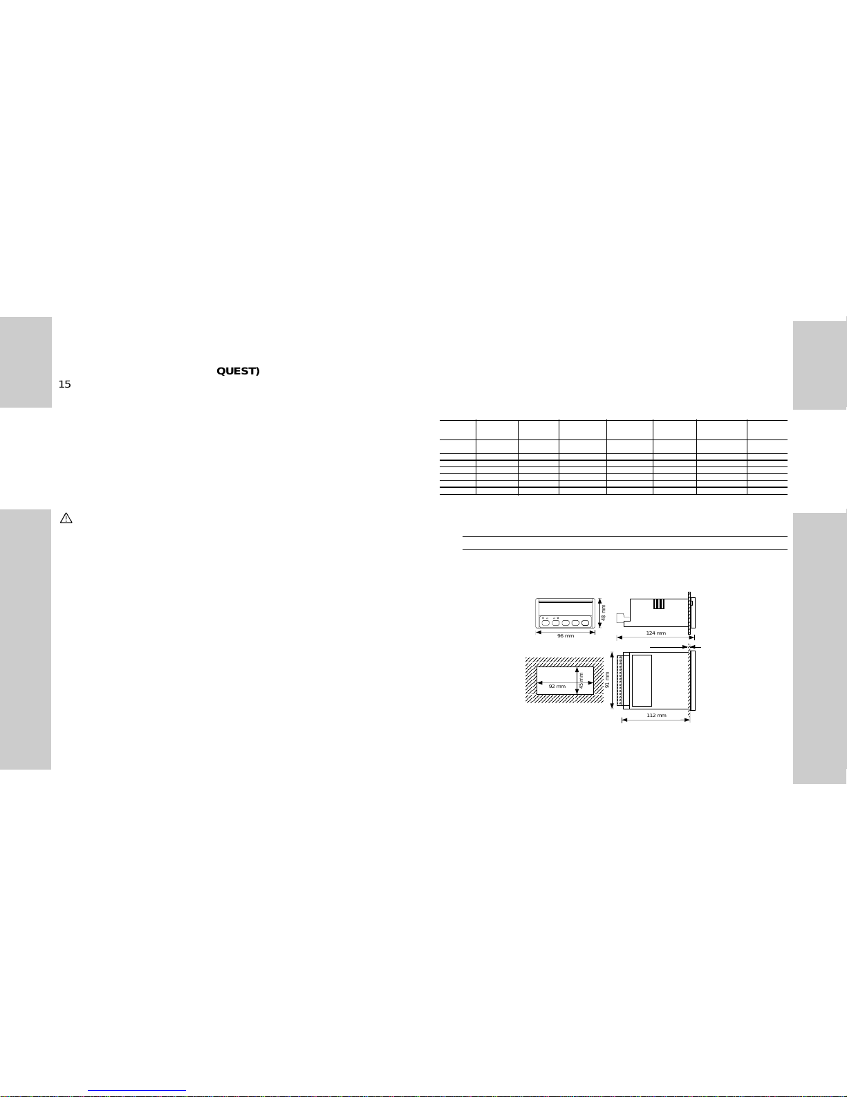
INSTALLATION
Overall dimensions and panel cut-out
AAAAAA
A
AAAAAA
A
AAAAAA
A
92 mm
45 mm
124 mm
F
S
al1
al2
96 mm
48 mm
91 mm
112 mm
max. 10
mm
EXCITATION OUTPUT (ON REQUEST)
15VDC / 40mA (12VDC / 60mA) (non-stabilized)
POWER SUPPLY INPUT
230VAC -15% +10% 50/60Hz (standard) (200mAT protection fuse*);
115 VAC -15% +10% 50/60Hz (on request) (200mAT protection fuse*);
48 VAC -15% +10% 50/60 Hz (on request) (630mAT protection fuse*);
24 VAC -15% +10% 50/60 Hz (on request) (630mAT protection fuse*);
120VAC-15% +10% 50/60 Hz (on request) (200mAT protection fuse*);
240VAC-15% +10% 50/60 Hz (on request) (200mAT protection fuse*);
9 to 32VDC galvanic insulation (1AT protection fuse*);
40 to 155VDC galvanic insulation (315mAT protection fuse*).
*note: the mains has to be protected by means of a proper fuse type
SELF CONSUMPTION
8VA
OPERATING TEMPERATURE
From 0 to +50°C (R.H. <90% non-condensing).
STORAGE TEMPERATURE
From -10 to +60°C (R.H. <90% non-condensing).
INSULATION REFERENCE VOLTAGE
300VRMS
INSTALLATION CATEGORY CAT III - 300V (EN61010-1).
DIELECTRIC STRENGTH 4000 VRMS for 1 minute.
EMC IEC 801-2, IEC 801-3, IEC 801-4 (level 3).
SAFETY STANDARDS EN 61010-1, IEC 1010-1, VDE 0411.
CONNECTIONS screw-type, detachable.
HOUSING SIZE / DIMENSIONS / MATERIAL
1/8 DIN / 48 x 96 x 124 mm / ABS, self-extinguishing: UL 94 V-0.
Page 7

9
ENGLISH
8
ENGLISH
Signal from a 2-wire inductive proximity
sensor (NAMUR). NOTE: When using
a NAMUR input, the terminals 5 and 6
must be jumpered.
Signal from capacitive or inductive
switches, type NPN or PNP, 3 wires.
NOTE: when using a NPN or PNP input, the terminals 6 and 7 must be
jumpered.
Signal from a PNP/NPN encoder
Mounting
Insert the instrument into the panel and fasten it by fixing the two lateral
brackets (1) supplied with the instrument to the appropriate location (2),
and subsequently locking them by means of the 2 screws (3) supplied
with the instrument.
Connections
According to the requirements of EN61010-1 the power supply
input of the instrument to be connected to the mains must be
protected against short circuit by means of appropriate fuses
(see "power supply input").
General connection label for MDI40.TF1
3
2
1
Page 8

11
ENGLISH
10
ENGLISH
AC signals from pick-up up to 100VAC
AC signals up to 500VAC
Double input signal from 2 capacitive or
inductive switches, type NPN or PNP, 3
wires.
NOTE: when using a NPN or PNP input, the terminals 6 and 7 must be
jumpered.
General connection label for MDI40.TF2
Page 9

13
ENGLISH
12
ENGLISH
FS
CARLO GAVAZZ
al1 al2
2
1
4
3
FRONT PANEL DESCRIPTION
1.Key-pad:
functions available outside the programming phase.
Keys to be pressed:
Displays set-point 1 corresponding to a password between 0
and 255;
Displays set-point 2 corresponding to a password between 0
and 255;
For longer than 2 seconds: modification of set-point 1 (pass-
word between 128 and 255 only);
For longer than 2 seconds: modification of set-point 2 (pass-
word between 128 and 255 only);
The command input (display hold function or key-pad disabling) must be
connected across the terminals 3 and 4 (only free of voltage contact).
The voltage signals must be connected as follows:
• 500V , channel A to the terminals 1 and 5, channel B to the terminals 3
and 5.
• 100V , channel A to the terminals 2 and 5, channel B to the terminals 4
and 5.
Note: when using only input channel A, connect the unused B channel
terminals 3 and 4 to the terminal 5
The command input (display hold function or key-pad disabling) must be
connected across the terminals 5 and 6 (only free of voltage contact).
PRELIMINARY OPERATIONS
Before supplying the instrument, make sure that the power supply
voltage correspond to what is shown on the label. Example:
MDI40.TF1.D.2.A.XX.IX
SER.N. 990600/20078
POWER 230 VAC 50/60 Hz
INPUT NPN, PNP
N. 2 control set points
OUTPUT 0/20 mA - 0/10 VDC
Page 10

15
ENGLISH
14
ENGLISH
modification of the selection or programming will not be saved if the
S
key has not been previously pressed)
2.Display
Alphanumeric indication by means of a 7-segment display:
• of the measured value;
• of the programming parameters;
• of the measuring abnormal conditions.
3.LED
Indication of the alarm set-point status.
4.Engineering unit window
To insert the interchangeable engineering unit in the special
window, proceed as follows: remove the front cover by inserting a
suitable screw driver in the special slot on the short sides of the front
panel; force gently until the front cover is completely removed. Insert
the desired engineering unit by means of a pair of tweezers. Replace
the front cover by inserting it first in the lower part and then in the upper
part of the locking system.
OPERATING MODE
• Power-on
When you switch the unit on, the display shows for approximately 5
seconds the instruments' software revision, for example: r.0.
• Displaying, control and diagnostics
The instrument shows continuously the value of the input variable as
defined in the programming phase.
+ Displays highest measured value (peak function);
+ Displays lowest measured values (valley function);
For longer than 2 seconds: acknowledge of an alarm (if the
relays have the latch function)
1. Key-pad:
functions available in the programming phase.
Keys to be pressed:
For longer than 2 seconds: programming phase entry and
password confirmation;
Menu selection (from the first to the last);
Menu selection (from the last to the first);
Confirmation and entry:
• in the configuration menus;
• in the secondary menus relating to parameters.
In the selected menu / secondary menu:
• increase of displayed value
• modification of parameter selection;
In the selected menu/secondary menu:
• decrease of displayed value
• modification of parameter selection;
In the menus: exit from the programming phase (message
"End" on the display) and return to the measuring and control function;
In the secondary menus: exit and return to the main menu (
the
F
F
F
F
S
S
Page 11

17
ENGLISH
16
ENGLISH
"PAS" message for the second time; enter the desired numerical code
using the "
" or " " keys, then confirm it by pressing the "S" key:
the display will show the first configuration menu ("InP");
•if the Password has already been entered, you can modify it following
the procedure described at No. 2); after the "PAS" message has been
shown a second time, enter the new numerical code using the "
"
or "
" keys and confirm it by pressing the "S" key: the display will
show the first configuration menu ("InP").
Data protection levels:
•if the Password is "0", the configuration data are not protected by
undesired access;
•if the Password is a number between "1 and 127", the configuration data
are entirely protected against undesired access;
•if the Password is a number between "128 and 255", the configuration
data are protected against undesired access except for the programming of the values ("SEt") of set-point 1 and/or 2.
It is possible to reset the Password by entering the number 3584.
•All programming/configuration steps of the instrument are shown
in the flow chart on the last page of this manual. The flow chart
gives the operator a better understanding of the programming
structure of the instrument, indicating the current function with
regard to the others. The flow chart also makes it easier to
understand the commands used in the programming phase.
See the chapter "Front panel description" for information regarding the
use of the key-pad and the relevant main functions.
The value shown on the display is continuously compared with the value
of the two set-points and of the other parameters, thus generating the
control function by energizing/de-energizing the output relays.
• Programming
This phase is identified by the blinking of the decimal point on the right
side of the display.
To enter the programming phase, press the "
S
" key until "PAS" is
shown on the display; then "0" is displayed: the correct numerical code
(Password) is to be entered. The following conditions may occur:
• 1) the operator hasn't entered any Password: press the "S" key
again to enter the configuration menus of the instrument;
• 2) the operator has already entered a Password: select the correct
Password by means of the "
" key (to increase the value) or " "
key (to decrease it) until the desired value is displayed. Press the "S"
key to confirm the value: if the Password is correct, then the display will
show "PAS" again followed by the relating numerical code; press the
"S" key once more in order to display the first configuration menu; if
the Password is not correct, the display shows "End" and the instrument
goes back to the measuring and control phase.
PROGRAMMING OF A NEW PASSWORD AND AUT OMATIC SELECTION OF THE PROTECTION LEVEL OF THE CONFIGURATION
DATA.
To enter the new Password:
•if the Password is "0", press the "S" key when the display shows the
Page 12

19
ENGLISH
18
ENGLISH
F1 : frequency, tachometer, rate mode A or B channel
The instrument measures the frequency either on input A or on input B
and executes the following calculation: display=Fa/Pu.1*PS.1 (or Fb/
Pu.2*PS.2). It can be used, for example, to measure the rotation speed
of a motor, or to display frequency in Hz and kHz, as tachometer mode:
RPS, RPM, RPH, MPS, MPM, MPH and as rate meter: flow (m
3
, cm3,
mm3,kg/m3, g/cm3, l/s, l/min, l/h, m3/s, m3/min, m3/h, t/h, kg/s) or speed
(mm/s, cm/s, m/s, mm/min, cm/min, m/min, mm/h, cm/h, m/h, km/h, in/
s, ft/s, yd,s, in/min, ft/min, yd/min, in/h, ft/h, yd/h).
F2 : A - B, frequency (speed) difference
The instrument measures the frequency of input A and input B and
executes the following calculation: display=(Fa/Pu.1*PS.1)-(Fb/
HOLD
Input
Input A
Display
HOLD
Input
Input A - B
Display
Glossary of displayed symbol:
• PAS :
protection key: programmable
from 0 to 255.
• InP : input range selection menu:
r1 : from 0.001 to 500 Hz or from
2ms to 1000s;
r2 : from 0.1 to 50 KHz or from
20µs to 10s
• t.ba :
time base programming menu:
values programmable from 0.1 to 999.9;
it is the updating time of both measurement and display.
• oPr :
operating mode selection menu:
General information:
"A" means always channel A input;
"B" means always channel B input;
the signal on the channel A is managed
always according to this formula: (Fa/
Pu.1)*PS.1; the signal on the channel
B is managed always according to this
formula: (Fa/Pu.2)*PS.2. Where: Fa or
Fb is the frequency signal measured on
channel A or B; Pu.1 or Pu.2 is the
number of pulses per revolution generated by the sensor connected to channel
A or B; PS.1 or PS.2 is the prescaler
value of the sensor A or B.
Page 13

21
ENGLISH
20
ENGLISH
F4 : A/B, frequency (speed) ratio mode
The instrument measures the frequency of input A and input B and
executes the following calculation: display=(Fa/Pu.1*PS.1)/(Fb/
Pu.2*PS.2). This measuring capability is ideal for monitoring the relative
speeds of shafts, conveyor belts and other moving machinery.
F5 : B/(A+B)*100
The instrument measures the frequency of input A and input B and
executes the following calculation: display=(Fb/Pu.2*PS.2)/[(Fa/
Pu.1*PS.1)+(Fb/Pu.2*PS.2)]*100. This measuring capability is used in
all the applications where it is necessary to measure a mixture flow
between two liquids. If the instrument is equipped with an analogue
output, this signal can be transmitted to a paper recorder to show the
HOLD
Input
Input B/(A+B)
Display
HOLD
Input
Input A/B
Display
Pu.2*PS.2). This result represents the difference between the input
channels and can be used when the speed difference between two
conveyor belts has to be as low as possible without considering the
reference speed of the first conveyor (in any case within a well known
value that can be controlled by the available alarm set-point) in order to
avoid any transportation problem of the produced goods.
F3 : (A - B)/B*100, frequency (speed) error ratio
The instrument measures the frequency of input A and input B and
executes the following calculation: display=[(Fa/Pu.1*PS.1)-(Fb/
Pu.2*PS.2)]/(Fb/Pu.2*PS.2)*100. This result represents the relative
error between the 2 input channels; this measuring capability is used
when the speed difference between two conveyor belts has to be as low
as possible in any case within a well known value that can be controlled
by the available alarm set-points. If the instrument is equipped with the
analogue output, this signal can be used to correct the speed of the
second conveyor belt.
HOLD
Input
Input (A-B)/B
Display
Page 14

23
ENGLISH
22
ENGLISH
• if the time base is, for instance, three times the period being measured
(see figure below), the updating of the display is made at the end of the
time base (end gate time) as average calculation of the measured
periods P=(P1+P2+Pn)/n
F7 : A, frequency (speed) clockwise and counter clockwise rotation
sensing mode.
This measuring capability is ideal for monitoring the relative speed of
shafts, conveyor belts and other moving machinery taking into account
the rotation mode, showing the reverse speed by means of a " - " sign.
The rotation sensing is detected by means of a phase difference,
measured using the two input channels available as standard in the
instrument. If we assume that the channel A is the main channel ( see
figure on the next page), the channel B is used to detect if a signal
arrives "after" (phase displacement) the signal of the main channel
(begin gate time) meaning "clockwise" rotation or "before" meaning
mixture deviation that is connected to the quality result of the mixture
itself.
F6 : 1/A, period or average period mode
The instrument measures the frequency of input A or input B and
executes the following calculation: display=1/(Fa/Pu.1*PS.1). The time
period is directly connected to the time base that has been programmed
in the instrument (for low frequencies or long time periods):
• if the time base is in the range of the period being measured (see figure
below), the updating of the display is as fast as possible and any period
changing is updated immediately on the display;
Page 15

25
ENGLISH
24
ENGLISH
• SCA: scaling factor programming
menu.
This menu allows to scale the input
signals coming from both A and B measuring channels in such a way that they
can be shown on the display as a rate,
a frequency, a period or a speed.
The parameters that allow to scale this
input signals according to the needs
are:
Pu.1 : number of pulses per revolution
of the sensor (proximity switch) connected to channel A . Programmable
value: 1<Pu.1<9999.
PS.1 : Prescaler channel A stated in
the following way: A1*10
b1
.
A1 : 1<A1<9999.
b1 : -9<b1<9.
Pu.2 : number of pulses per revolution
of the sensor (proximity switch) connected to channel B . Programmable
value: 1<Pu.1<9999.
PS.2 : Prescaler channel B stated in
the following way: A2 *10
b2
A2 : 1< A2 < 9999.
b2 : -9 < b2 < 9.
"counter clockwise rotation". Such kinds of signals are normally generated by standard encoders.
Page 16

27
ENGLISH
26
ENGLISH
For instance, if the wheel has 30 cogs (30 references) that can be
detected by an inductive proximity switch, at the end of its rotation it
generates 30 pulses, so the number that has to be programmed as Pu.1
or Pu.2 parameter is 30. Pay attention: if, instead of a speed or a rate,
you have to measure and display a frequency or a period, Pu.1 and Pu.2
have to be "1" (pulse per revolution).
First example:
if you have to measure a speed of a motor with the following data:
motor speed: 800 RPM;
pulses per revolution : 1;
requested displayed value: 800 RPM;
you have to proceed in the following way:
calculate the
maximum frequency that is given by:
"[max. speed (RPM) * pulses per revolution]/60", that takes in our case:
"[800 * 1]/60 = 13.33Hz"
•
"InP": to select the proper input range that is connected to the
maximum frequency. You have to measure, in our case, 13.33Hz,
therefore the range is "r1" (from 0.001Hz to 500Hz). With the "r1" range
you can easily calculate the minimum speed the instrument can
measure and display: "[min. frequency (Hz) * 60] / pulses per revolution"
that takes in our case "[0.001 * 60]/1=0.06 RPM".
•
"t.bA": to select the proper time base in order to exploit the maximum
performance of the instrument. If the speed of the motor can be adjusted
from 100 RPM to 800 RPM we can calculate the time period corresponding to the minimum speed that is given by: "60/[min. speed
(RPM)* pulses per revolution]", that takes in our case "60/[100*1]= 0.6
What is the meaning of "prescaler"? It's a multiplier used to multiply the
measured frequency by a programmable value in order to achieve the
desired value on the display.
To allow the scaling capability of the instrument to be as powerful as
possible, this parameter has been divided into two sub parameters:
the mantissa "A" and the exponent "b". The prescaler is stated as
A * 10
b1
.
The calculation capability is from:
9999 * 10
-9
(0.000009999) max. divisor;
1 * 10
-1
(0,1) min. divisor;
9999 * 10
9
(9999000000000) max. multiplier;
1 * 10
0
(1) min. multiplier.
What is the meaning of "pulses per revolution"? It is the number of
pulses that are generated by the input connected sensor for every
complete revolution (360°) of the wheel or of the drive shaft being
detected.
Page 17

29
ENGLISH
28
ENGLISH
Second example:
if you have to measure the speed difference between two wheels,
detected by 2 inductive sensors, that have the following data:
Wheel number 1 (connected to the channel "A" of the MDI40):
max rotational speed: 700 RPM;
pulses per revolution: 4.
Wheel number 2 (connected to the channel "B" of the MDI40):
max rotational speed: 600 RPM;
pulses per revolution: 4.
you have to proceed in the following way:
calculate the
maximum frequency that is given by:
"[max. speed (RPM) * pulses per revolution]/60", that makes in our
case, for wheel 1: Fa = (700 * 4)/60 = 46.66Hz
for wheel 2: Fb = (600 * 4)/60 = 40.00Hz
•
"InP": to select the proper input range that is connected to the
maximum frequency you have to measure; in our case the value is
between 40Hz and 50Hz, therefore the range is "r1" (from 0.001Hz to
500Hz). With the "r1" range you can easily calculate the minimum speed
the instrument can measure and display: "[min. frequency (Hz) * 60] /
pulses per revolution" that makes in our case "[0.001 * 60]/4=0.015
RPM".
•
"t.bA": to select the proper time base in order to exploit the maximum
performance of the instrument. If the speed of the two wheels can be
adjusted from 100 RPM to 700 RPM (for the first wheel) and from 100
to 600 (for the second one), we can calculate the time period corresponding to the minimum speed that is given by: "60/[min. speed
(RPM)* pulses per revolution]", that makes in our case "60/[100*4]=
sec., therefore the "t.bA" would be "0.6", better if "0.7".
•
"oPr": to perform the measurement of a "speed" you have to choose
the "F1" function
•
"SCA"
•
"Pu.1": the number of "pulses per revolution" is in our case "1",
therefore "Pu.1" becomes 1.
•
"PS.1": the prescaler formed by the two sub-parameters "A1", mantissa, and "b1", exponent, has to be set in the following way:
the maximum read-out capacity of the instrument is 9999, that means
the speed can be shown as 800.0 "RPM". We have to measure "800"
but to obtain the maximum speed resolution we have to display 8000
(don't consider the decimal point). The calculation made by the
instrument according to function selection "F1" is the following:
value to be displayed = (Fa * PS.1) / Pu.1 (1)
- "Fa" according to the frequency of 800 RPM is 13.33Hz;
- "Pu.1" is 1;
- "PS.1" can be calculated from the above mentioned formula (1) that
means: (value to be displayed * Pu.1) / Fa, that makes :
(800*1) / 13.33 = 60.01, that means: 60.01 = A1*10
b1
therefore A1=6001 and b1 = -2 (10 b1 → 0.01)
•
"dSY": to show on the display 800.0 we have to move the decimal point
to "111.1";
•
"Lo": see the proper explanation on the next pages;
•
"Hi": see the proper explanation on the next pages;
The PS.2 menu is not available for the functions F1, F6 and F7.
Page 18

31
ENGLISH
30
ENGLISH
that means: PS = (value to be displayed * Pu.1) / (Fa - Fb), that makes:
(100 * 4) / 6.66 = 60.06, that means: 60.06=A*10
b
therefore A = 6001 and b = -2 (10 -2 → 0.01)
•
"Pu.2": the number of "pulses per revolution", of channel "B", is in our
case "4", therefore "Pu.2" becomes 4.
•
"dSY": to show on the display 100.0 we have to move the decimal point
to "111.1";
•
"Lo": see the proper explanation on the next pages;
•
"Hi": see the proper explanation on the next pages:
Parameter table (suggested values)
Rotational
Speed
FUNCTION
(
oPr
)
MEASUREMENT
RPS
RPM
RPH
UNIT
(
displa
y)
TIME BASE
(t.bA)
PULSE / REVOL.
(PU.1) (Pu.2)
PRESCALER
(PS.1) (PS.2)
Linear Speed
(circumferential
speed)
F1, F2
F3, F4
1
60
60
1
1
1
mm/s
cm/s
m/s
mm/min
cm/min
m/min
1
1
1
60
60
60
F1, F2
F3, F4
cm/h
km/h
MPH
60
60
60
1
1
1
Hz
kHz
1
0,1
Frequency F1
m/h
60
60
mm/h
1
1
1
1
1
1
1
1
n
n
1
60
3600
π * d * 3600
π * d * 3.6
π * d * 2.23
1000 * π * d
100 * π * d
π * d
1000 * π * d * 60
100 * π * d * 60
π * d * 60
1000 * π * d * 3600
100 * π * d * 3600
n
n / 1000
0.15 sec., therefore the "t.bA" would be "0.15", better if "0.2".
•
"oPr": to perform the measurement of a "speed difference" you have
to choose the "F2" function
•
"SCA"
•
"Pu.1": the number of "pulses per revolution" of channel "A", is in our
case "4", therefore "Pu.1" becomes 4.
•
"PS.1": the prescaler of channel "A", formed by the two sub-parameters "A1", mantissa, and "b1", exponent. It must be equal to the
prescaler of channel "B", "PS.2".
•
"Pu.2": the number of "pulses per revolution", of channel "B", is in our
case "4", therefore "Pu.2" becomes 4.
•
"PS.2": the prescaler of channel "B", formed by the two sub-parameters "A2", mantissa, and "b2", exponent. It must be equal to the
prescaler of channel "A" and can be calculated in the following way:
the maximum read-out capacity of the instrument is 9999, that
means the minimum speed difference (given subtracting the max.
speed of channel "A" and the one of channel "B") can be shown as
100.0 "RPM". We want to measure "100" but to have the maximum
speed resolution we have to display 1000 (don't consider the decimal point). The calculation made by the instrument according to
function selection "F2" is the following:
value to be displayed = [(Fa * PS.1) / Pu.1 - (Fb * PS.2) / Pu.2 ] (1)
- PS.1 = PS.2 = PS that means: A1 = A2 = A and b1 = b2 = b
- Fa according to the frequency of 700 RPM is 46.66Hz;
- Fb according to the frequency of 600 RPM is 40.00Hz;
the prescaler can be calculated from the above mentioned formula (1)
Page 19

33
ENGLISH
32
ENGLISH
• Cnd : auxiliary command selection
menu
r1 : display HOLD.
r2 : key-pad disabling.
t.in : activation time of the auxiliary
input, programmable value: 20 < t.in <
255 msec.
• SP.1 / SP.2 :
set-point programming
menu
tYP : working type:
oFF : abnormal condition notifying. The
output will be activated either when
the measurement is out of the measuring range or when it cannot be displayed
(blank display or "EEE" / "-" indication on the display).
Note: if the above mentioned function
will be selected, the Lo.S, Hi.S, SP1,
HYS parameters will not be considered.
do : down alarm.
uP : up alarm.
d.do: down alarm with disabling at
power-on.
uP.L: up alarm with latch ( the alarm
•
•
•
•
•
•
Where:
d = diameter of the circumference
n = number of pulses per revolution
dSY :
display parameter programming
menu
d.P : decimal point position selection.
Lo : minimum value of the display
scale, programmable value: -1999 < Lo
< 9999
Hi : maximum value of the display
scale, programmable value: -1999 < Hi
< 9999
These values are referred only to the
output limits of the analogue output and
to the "OFF" alarm function.
For instance: if Lo=100.0 and hi=800.0
and the alarm type "TYP" is "OFF", the
display will blink and activate the relevant output when the measured
variable goes out of the "100.0 to 800.0"
limits. If the analogue output is available, the output signals will start from
"100.0" and will arrive to "800.0".
Page 20

35
ENGLISH
34
ENGLISH
Example:
“do” alarm, if “SEt”=2200 (value of the ON alarm status) and the
hysteresis “HYS”=12, the resulting OFF value (end of alarm status) is:
2212 (resulting from 2200 +12).
“uP” alarm, if “SEt”=2200 (value of the ON alarm status) and the
hysteresis “HYS”=12, the resulting OFF value (end of alarm status) is:
2188 (resulting from 2200 - 12).
NOTE: the hysteresis is to be programmed according to the displayed
range. This means that the hysteresys must always be much lower than
the displayed range.
of.d : OFF time delay; programmable
value: 0 < OF.d < 255.
on.d : ON time delay; programmable
value: 0 < On.d < 255.
rL Y : coil status of the relay in the
normal condition:
nd : normally de-energized coil.
nE : normally energized coil.
Note: the normally closed or open status of the alarm contact is modified by
means of an inside selectable solder
jumper.
•
•
•
•
•
•
can be reset only if the "F" key will be
held down for at least 2 seconds).
do.L : down alarm with latch ( the alarm
can be reset only if the "F" key will be
held down for at least 2 seconds).
Lo.S: value of the lower Set-point limit,
programmable value: Lo(Hi) < LoS <
Hi(Lo).
Hi.S : value of the upper Set-point
limit, programmable value: Lo.S < Hi.S
< Hi(Lo)
SEt : value of the Set-point; program-
mable value: Lo.S < SEt < Hi.S.
HYS : hysteresis value of the set-point.
The hysteresis is a numerical value
included within the range: 0 < HYS <
9999 and represents the difference
between the value of the ON alarm
status and the value of the OFF alarm
status. The hysteresis modifies the
value of the OFF alarm status not only
with regards to the set alarm value, but
also with regards to the alarm type: the
hysteresis value is summed to the set
value if the alarm type is "do" and
subtracted from the set value if the
alarm type is "uP".
•
•
•
•
•
•
•
•
•
•
•
•
Page 21

37
ENGLISH
36
ENGLISH
played value, the control set-points and
the analogue output.
NOTE: for a correct working of the
filter, the relative coefficient must satisfy the following relationship: 1 < Fi.C
< (Fi.S x 8) < 255.
• A.ou :
analogue output programming
menu.
Lo.A : value to be expressed as % of
the output range (0/20mA-0/10V) to be
generated in correspondence with the
minimum measured value. Value programmable within the range: 0.00 < Lo
< 99.99.
Hi.A :
value expressed as % of the
output range (0/20mA-0/10V) to be generated in correspondence with the
maximum measured value (Hi.E/Hi parameters). V alue to be programmed within
the range: 0.00 < Hi.A < 99.99.
Example: minimum measured value = 100, that must correspond to a
retransmitted signal of 4mA.
“Lo.A” (%) =
100 * ?mA that in our example corresponds to:
20
• FiL : filter parameter programming
menu.
This function allows you to stabilize the
instruments digital display, in order to
obtain steady readings and better control.
Fi.S : filter working range. The coeffi-
cient is given in digits and defines the
range in which the filter works, programmable value: 0 < Fi.S < 9999
The programmable numerical value
represents the fluctuation range of the
value which has been measured and
displayed by the instrument. In the first
configuration phase this value must be
0 and the right value is to be entered
only after the verification of the possible fluctuation.
Example: if the measured instantaneous value varies from 10.00 to 10.06,
the "Fi.S" value to be entered is 0.06
(10.06 - 10.00).
Fi.C : filtering coefficient value. Pro-
grammable value: 1 < Fi.C < 255.
The higher "Fi.C", the higher the filtering of the measured value and the
longer the updating time of the dis-
Page 22

39
ENGLISH
38
ENGLISH
• S.ou: selection menu of the serial
communication output.
Add : programmable address value:
1 < Add < 255
b.dr : programming of the data baud
rate:
r1: 1200 bps.
r2: 2400 bps.
r3: 4800 bps.
r4: 9600 bps.
100 * 4mA/20 = 20%, therefore enter 20.00.
Example: minimum measured value = 100, that must correspond to a
retransmitted signal of 1V.
“Lo.A” (%) =
100 * ?V that in our example corresponds to:
10
100 * 1V/10 = 10%, therefore enter 10.00.
Example: maximum measured value 800, that must correspond to a
retransmitted signal of 18mA.
“Hi.A” (%) =
100 * ?mA that in our example corresponds to:
20
100 * 18mA/20 = 90%, therefore enter 90.00.
Example: maximum measured value 800, that must correspond to a
retransmitted signal of 5V.
“Hi.A” (%) = 100 * ?V that in our example corresponds to:
10
100 * 5V/10 = 50%, therefore enter 50.00.
Also in this case it is possible to invert the scale, that is, a decreasing
value of the retransmitted signal may correspond to an increasing value
of the input variable (example: Lo.A > Hi.A).
Page 23

40
ENGLISH
In the secondary menus: press the key to go
back to the main menu (
the selection or programming
modification will not be saved if the
key has not
been previously pressed)
YES
NO
In the menus: press the key in order to exit from the
programming phase: the display shows "End" and then the
measured value
 Loading...