

CARLO GAVAZZI LDI 35 - CONFIGURATION SOFTWARE, LDI35.AV0, LDI35.AV2, LDI35.CF Operating Instructions Manual
Page 1

ENGLISH
LDI 35
OPERATING INSTRUCTIONS
• General features 2
• Technical features 3
• Installation 10
• Preliminary operations 12
• Front panel description 13
• Operating mode 15
Important:
We suggest you keep the original packing for a further shipping of the
instrument.
In order to guarantee a correct use of the instrument, we recommend
the user to carefully read the present instruction manual.
Page 2

2
ENGLISH
CARLO GAVAZZI Instruments
Multi-range µP-based panel indicators/controllers for voltage, cur-
rent and temperature measurements
LDI35.AV0 / LDI35.AV2 / LDI35.CF
rev.0
Operating instructions
Important:
We suggest you keep the original packing for a further shipping of the
instrument.
In order to guarantee a correct use of the instrument, we recommend the
user to carefully read the present instruction manual.
GENERAL FEATURES
The most important features are:
•measurement of the input value;
•display of the measured value;
•one control point of the measured value (if available);
•display of the maximum measured value.
The main programming parameters are:
•input selection;
•programming of: electrical scale, displayed scale and decimal point
position;
Page 3

3
ENGLISH
•selection of displaying mode;
•programming of all the parameters relating to the set-point (if available);
•programming of all the parameters relating to the digital filter.
TECHNICAL FEATURES
ACCURACY (VOLTAGE AND CURRENT)
LDI35.AV0: ±0.3% F.S., ±1 dgt (@ 25°C ±5°C, R.H. ≤60%);
LDI35.AV2:
VDC and ADC: ±0.3% F.S., ±1 dgt (@ 25°C ±5°C, R.H. ≤60%);
V AC and AAC: ±0.5% F.S., ±1 dgt (@ 25°C ±5°C, R.H. ≤60%, 50/60Hz,
5 to 100% F.S.).
ACCURACY (LDI35.CF: RTD/Ω TEMPERATURE)
Pt100/Pt1000: ±0.3% F.S., ±2 dgt (@ 25°C ±5°C, R.H. ≤60%);
Ni100: ±0.5% F.S., ±2 dgt (@ 25 °C ±5°C, R.H. ≤60%);
Ω: ±0.3% F.S., ±2 dgt (@ 25°C ±5°C, R.H. ≤60%).
ACCURACY (LDI35.CF: TC TEMPERATURE)
±0.3% F .S., ±2 dgt (@ 25°C ±5°C, R.H. ≤60%) from -50°C to the limit of
the input range;
±1% F .S., ±2 dgt (@ 25°C ±5°C, R.H. ≤60%) from -200°C to -5°C of the
input range.
TEMPERATURE DRIFT (VOLTAGE AND CURRENT)
LDI35.AV0: ±200 ppm/°C;
LDI35.AV2: ±200 ppm/°C.
Page 4

4
ENGLISH
TEMPERATURE DRIFT (LDI35.CF: RTD / TC / Ω)
± 200 ppm/°C.
SAMPLING RATE
LDI35.AV0: 4 times/second, dual slope 16 bits A/D converter
LDI35.AV2: 2 times/second, dual slope 16 bits A/D converter
LDI35.CF temperature measurement: 2 times/second, dual slope
16 bits A/D converter
DISPLAY
7-segment LED, h 14.2 mm; 3 1/2 digits or 3 digits + dummy zero.
MAXIMUM INDICATIONS
LDI35.AV0: 3 1/2 digit: 1999; 3 + 0 digit: 9990;
LDI35.AV2: 3 1/2 digit: 1999 (DC/AC); 3 + 0 digit: 9990 (DC/AC);
LDI35.CF: temperature: depending on the range and on the type of
probe; resistance: 199.9 Ω (STD) / 1999 Ω (on request).
MINIMUM INDICATIONS
LDI35.AV0: 3 1/2 digit: -1999; 3 + 0 digit: -1990;
LDI35.AV2: 3 1/2 digit: -1999 (DC), 0 (AC); 3 + 0 digit: -1990 (DC), 0 (AC).
LDI35.CF: temperature: depending on the range and on the type of
probe; resistance: 0.
MEASUREMENT (VOLTAGE / CURRENT)
LDI35.AV0: DC voltage/current.
LDI35.AV2: DC voltage/current and AC voltage/current (measurement
Page 5

5
ENGLISH
of the average value resulting from the sine half-wave rectification of the
input voltage/current by RMS calibration).
VOLTAGE / CURRENT INPUTS (LDI35.AV0)
200 mVDC, range: -199.9 mVDC to 199.9 mVDC
20 VDC, range: -19.99 VDC to 19.99 VDC
200 VDC, range: -199.9 VDC to 199.9 VDC
2 mADC, range: -1.999 mADC to 1.999 mADC
20 mADC, range: -19.99 mADC to 19.99 mADC
Other inputs are available by acting on the scaling parameters.
VOLTAGE / CURRENT INPUTS (LDI35.AV2)
200 VDC, range: -199.9 VDC to 199.9 VDC
500 VDC, range: -500 VDC to 500 VDC
2 ADC, range: -1.999 ADC to 1.999 ADC
5 ADC, range: -5.00 ADC to 5.00 ADC
200 VAC, range: 0 VAC to 199.9 VAC
500 VAC, range: 0 VAC to 500 VAC
2 AAC, range: 0 AAC to 1.999 AAC
5 AAC, range: 0 AAC to 5.00 AAC
Other inputs are available by acting on the scaling parameters.
FREQUENCY RANGE (VOLTAGE / CURRENT - LDI35.AV2)
From 40 to 400 Hz (accuracy: ± 0.5% F.S., ± 2 dgt @ 25 °C, 400 Hz).
OVER-RANGE (VOLTAGE / CURRENT)
Continuous: 1.2 Un/In (rated inputs), for 1 second: 2 Un/In.
Page 6

6
ENGLISH
INPUTS (RTD TEMPERATURE / Ω)
CFX: RTD, Pt100, range: -200 °C / -328 °F to +850 °C / 1562 °F
CFX: RTD, Ni100, range: -60 °C / -76 °F to +180 °C / 356 °F
CFX: Ω, 200.0 Ω, range: 0 Ω to 199.9 Ω
CFP: RTD, Pt1000 range: -200 °C / -328 °F to +850 °C / 1562 °F
CFP: Ω, 2000Ω range: 0 Ω to 1999 Ω
Other inputs are available by acting on the scaling parameters.
INPUTS (TC TEMPERATURE)
CFX/CFP: TC-J, range: -50 °C / -58 °F to +760 °C /+1400 °F
CFX/CFP: TC-L, range: -50 °C / -58 °F to +760 °C / +1400 °F
CFX/CFP: TC-K, range: -200 °C / -328 °F to +1260 °C / +1999 °F
CFX/CFP: TC-S, range: +350 °C / +1750 °C
CFX/CFP: TC-T, range: -200 °C / -328 °F to +400 °C / +752 °F
Other inputs are available by acting on the scaling parameters.
COMPENSATION (RTD/Ω)
For 3-wire connections, line resistance up to 10 Ω.
COMPENSATION (TC)
Cold junction, within a temperature range from 0 to 50 °C of ambient
temperature.
ALARM SET-POINTS
0 (standard) 1 (on request).
Alarm type: the alarm is active only for under/over-range, high alarm, low
alarm, low alarm with disabling at power-on, high alarm with latch, low
Page 7

7
ENGLISH
alarm with latch.
Set-point and hysteresis level: programmable from 0 to 100% of the
displayed range;
Activation/deactivation time delay: programmable from 0 to 255 seconds;
Relay status: selectable; normally energized/de-energized;
Output contacts: 1 SPDT; rating: 5A, 250VAC/VDC, 40W/1200VA,
130.000 cycles;
min. response time: ≤500 ms (filter excluded, set-point activation time
delay: “0”);
Insulation: 2000VRMS between output and measuring inputs; 2000VRMS
between output and excitation output.
DIGITAL FILTER
Operating range: from 0 to 1999 / 9990;
Filtering coefficient: from 1 to 255.
DATA HOLD
Automatic storage (RAM only) of the maximum value measured from the
previous storage reset onwards.
EXCITATION OUTPUT VOLTAGE (on request)
15 VDC insulated, not stabilized / max. 40 mA.
EXCITATION OUTPUT INSULATION
100VRMS between output and measuring input
4000VRMS between output and AC power supply input
500VRMS between output and DC power supply input.
Page 8

8
ENGLISH
POWER SUPPLY INPUT
230 VAC -15% +10% 50/60 Hz (standard);
115 VAC -15% +10% 50/60 Hz (on request);
240 VAC -15% +10% 50/60 Hz (on request);
120 VAC -15% +10% 50/60 Hz (on request);
48 VAC -15% +10% 50/60 Hz (on request);
24 VAC -15% +10% 50/60 Hz (on request);
Insulation: 4000 VRMS between power supply input and all the other
inputs/outputs;
9 to 32 VDC, G.I., max. starting current: ≤1.2A/200 ms (on request);
40 to 150 VDC, G.I., max. starting current: ≤0.6A /200 ms (on request);
Insulation: 500 VRMS between power supply input and all the other inputs/
outputs;
Self-consumption: 6.5 VA.
OPERATING TEMPERATURE
From 0 to +50°C (R.H. < 90% non-condensing)
STORAGE TEMPERATURE
From -10 to +60°C (R.H. < 90% non-condensing)
STABILITY OF ACCURACY
6 months
REFERENCE VOLTAGE FOR THE INSULATION
300 VRMS to earth
Page 9

9
ENGLISH
DIELECTRIC STRENGTH
4000 VRMS for 1 minute
NOISE REJECTION
NMRR: 40 dB, from 40 to 60 Hz
CMRR: 100 dB, from 40 to 60 Hz
EMC: IEC 801-2, IEC 801-3, IEC 801-4 (level 3), EN 50081-1, EN 50082-1.
IN ACCORDANCE WITH THE FOLLOWING SAFETY STANDARDS
EN 61010-1, IEC 1010-1, VDE 0411.
CONNECTIONS
Screw-type terminal board.
CASE SIZE / DIMENSIONS / MATERIAL
1/8 DIN / 48 x 96 x 83 mm / ABS, self-extinguishing: UL 94 V-0.
WEIGHT
340 g. approximately (packing included).
PROTECTION DEGREE
IP 50 (standard) / IP 65 (on request).
Page 10

10
ENGLISH
INSTALLATION
Overall dimensions and panel cut-out
(all quotes are expressed in mm)
91 mm
75 mm
max. 10
mm
83 mm
AAAAAA
A
AAAAAA
A
AAAAAA
A
92 mm
45 mm
F
96 mm
48 mm
S
Mounting
Insert the instrument into the panel and fasten it by fixing the two lateral
brackets (1) supplied with the instrument to the appropriate location (2).
1
2
2
Page 11

11
ENGLISH
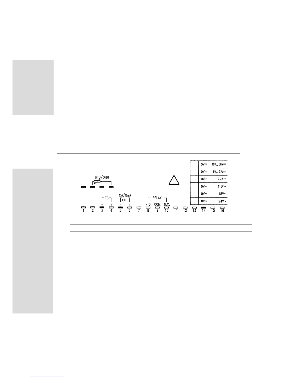
Connections
In order to select the desired range (LDI35.AV0), jumper, if necessary,
between the relevant screw terminals.
Connect LDI35.AV0 (voltmeter or ammeter) as shown in the figure.
Attention: the voltmeter input is to be connected in parallel to the source
to be measured.
Attention: the ammeter input is to be connected in series to the source
to be measured.
LDI35.AV2
LDI35.AV0
Page 12
12
ENGLISH
Connection of the signal transmitters (in the models LDI35.AV0 - 20mA):
• 2 wires: signal to the measuring input; power supply to terminal 6;
jumper also terminals 4 and 5; loop impedance 60 to 80 Ω (load 20mA).
• 3 wires: signal to the measuring input; power supply to terminals 5 and
6; jumper also terminals 4 and 5;
• 4 wires: signal to the measuring inputs; power supply to terminals 5 and 6.
Connect LDI35.CF (thermometer) as shown in the figure. For temperature/
resistances only: if there are two wires only, jumper terminals 3 and 4.
PRELIMINARY OPERATIONS
Before supplying the instrument, make sure that the power supply
voltage correspond to what is shown in the label. Example:
LDI35.AV0.D.1.XX.XX
SER.N. 970600/20078
POWER 230 VAC 50/60 Hz
INPUT CURRENT / VOLTAGE
N. 1 set point
LDI35.CF
Page 13

13
ENGLISH
FRONT PANEL DESCRIPTION
S
1. Key-pad:
functions available outside the programming phase.
Key to be pressed:
Displaying of set-point;
Displaying of maximum measured value (peak feature);
For longer than 5 seconds: reset of the maximum measured value
(the display will be blinking);
For longer than 5 seconds: reset of activated set-point (only for
set-point with latch).
1. Key-pad:
functions available in the programming phase.
Key to be pressed:
S
For longer than 2 seconds: programming phase entry and
password confirmation;
Page 14

14
ENGLISH
Menu selection (from the first to the last);
Menu selection (from the last to the first);
S
Confirmation and entry:
• in the configuration menus;
• in the secondary menus relating to parameters.
In the selected menu / secondary menu:
• increase of displayed value
• modification of parameter selection;
In the selected menu/secondary menu:
• decrease of displayed value
• modification of parameter selection.
2. Display
Alphanumeric indication by means of 7-segment LEDs:
• of the measured value;
• of the programming parameters;
• of the measuring abnormal conditions.
3. Engineering unit window
To insert the interchangeable engineering unit in the special
window, proceed as follows: remove the front cover by inserting a
suitable screw driver in the special slot on the short sides of the front
panel; force gently until the front cover is completely removed. Insert
the desired engineering unit by means of a pair of tweezers. Replace
Page 15

15
ENGLISH
the front cover by inserting it first in the lower part and then in the upper
part of the locking system.
OPERATING MODE
• Power-on
When you switch the unit on, the instrument shows for approximately 5
seconds the instruments’s software revision, for example: r.1.
• Displaying, control (if present) and diagnostics
The instrument shows continuously the value of the input variable as
defined in the programming phase.
The value shown on the display is continuously compared with the value
of the set-point and of the other parameters, thus generating the control
function by energizing/de-energizing the output relay.
• Programming
This phase is identified by the blinking of the decimal point on the right
side of the display.
To enter the programming phase, press the
S
key until “PAS” is
shown on the display; then “0” is displayed: the correct numerical code
(password) is to be entered. The following conditions may occur:
• 1) the operator hasn’t entered any Password: press the
S
key again
to enter the configuration menus of the instrument;
Page 16

16
ENGLISH
• 2) the operator has already entered a Password: select the correct
password by means of the
key (to increase the value) or key
(to decrease it) until the desired value is displayed. Press the
S
key
to confirm the value: if the password is correct, then the display will show
“PAS” again followed by the relating numerical code; press the
S
key
once more in order to display the first configuration menu; if the password
is not correct, the display shows “End” and the instrument goes back to
the measuring and control phase.
PROGRAMMING OF A NEW PASSWORD AND AUTOMATIC SELECTION OF THE PROTECTION LEVEL OF THE CONFIGURATION
DATA.
To enter the new Password:
•if the Password is “0”, press the
S
key when the display shows the
“PAS” message for the second time; enter the desired numerical code
using the
or keys, then confirm it by pressing the
S
key:
the display will show the first configuration menu (“inP”);
•if the Password has already been entered, you can modify it following
the procedure described at No. 2; after the “PAS” message has been
shown a second time, enter the new numerical code using the
or
keys and confirm it by pressing the
S
key: the display will show
the first configuration menu (“inP”).
Data protection levels:
•if the password is “0”, the configuration data are not protected by
undesired accesses;
Page 17

17
ENGLISH
•if the Password is a number between “1 and 255”, the configuration data
are entirely protected against undesired accesses;
It is possible to reset the Password by entering the number 768.
•All programming/configuration steps of LDI35 are shown in the
flow chart in the centre of this manual. The flow chart has been
conceived to make the operator better understand the programming structure of LDI35 indicating the position of the current
function with regards to the others. The flow chart also makes
more easily understandable the commands to be used in the
configuration phase.
•See the chapter “Front panel description” for information regarding the use of the key-pad and the relevant main functions.
•Glossary of displayed symbol:
(the symbols like P AS in a black background belong to the main menu;
the symbols like AC in a white background belong to the secondary menu).
PAS : access key to programming
inP : menu to select measuring inputs
For LDI35.AV2 only:
AC : AC voltage/current measurements;
dC : DC voltage/current measurements.
For LDI35.CF only:
rtd : thermoresistance/Ohm measurements;
tC : thermocouple measurements
r1 , r2 , r3 , r4 , r5 : range selection (see table “inP” in the
flow chart).
SCA : menu to program the scaling parameters
Page 18

18
ENGLISH
Lo.E: programming of the min. value of the electrical scale (see table
“inP” in the flow chart). Enter the minimum value that is to be measured
(zero scale).
Hi.E : programming of the max. value of the electrical scale (see table
“inP” in the flow chart). Enter the maximum value to be measured (full
scale).
NOTE: in the resistance measurements (“inP” ⇒ “rtd” ⇒ “r5”) the
maximum electrical full scale to be entered is: “1999” and the corresponding value of “Hi” must be “199.9” in order to take resistance
measurements with a 0.1Ω resolution.
NOTE: if the measured variable goes beyond the scale limits “Lo.E”/
”Hi.E”, the value displayed during the measuring phase will be blinking
and updated with reference to the measured value up to the maximum
displaying range (“dC” and temperature measurements: -1999/1999;
“AC” and resistance measurements: 0/1999).
d.P : selection of the decimal point position in the “Hi-Lo” scale.
Lo : programming of the min. value of the displayed scale. Enter the
value to be displayed in correspondence with the minimum value of the
electrical scale “Lo.E”.
Example: “Lo.E”=4.00 mA ⇒ “Lo”=100 mbar , means that when the value
measured by LDI35 is 4 mA, the displayed value will be 100 mbar.
Hi : programming of the max. value of the displayed scale. Enter the
value to be measured in correspondence with the maximum value of the
electrical scale “Hi.E”. Example: “Hi.E”=19.99 mA ⇒ “Hi”=1800 mbar,
means that when the value measured by LDI35 is 20 mA, the displayed
value will be 1800 mbar.
NOTE: electrical scale and displayed scale must have:
Page 19

19
ENGLISH
• corresponding values (Lo.E = Lo, Hi.E = Hi), if the same value is to be
both measured and displayed.
• different values, if the signal to be measured is different from the one
to be displayed (see examples of “Lo” and “Hi”).
• inverted values, if an increasing signal to be measured must correspond to a decreasing value to be displayed (scale inversion).
Example:
“Lo.E”=4.00 mA ⇒ “Lo”=1800 mbar; “Hi.E”=19.99 mA ⇒ “Hi”=0 mbar ,
means that when the measured value increases from 4 to 20mA, the
displayed value decreases from 1800 mbar to 0.
As you can see, the scales can be programmed with absolute freedom.
NOTE: to display temperature values as “°F”, it is necessary to program
the electrical scale as “°C” and enter the values for the displayed scale
according to the following relationship:
°F = (1.8 x °C) + 32.
Example:
“Lo.E”=-50 °C ⇒ “Lo”=-58 °F; “Hi.E”=+760 °C ⇒ “Hi”=+1400 °F,
means that the new measuring range becomes -58 °F to +1400 °F . The
data to be entered in the displayed scale can be calculated either by
means of the above mentioned “°F” relationship, or using the data of the
relevant measuring range (see chapter “T echnical Features”, paragraph
“Inputs (temperature)”.
diS : menu to select the displaying mode.
35 : displaying at 3 1/2 digit (1999)
30 : displaying at 3 digit + dummy zero (9990).
SP.1 : menu to select the programming of the set-point parameters.
tYP : selection of the type of control.
oFF : signalling of the abnormal condition. The relay is activated when
a burn-out condition occurs or the measurement is out of the electrical
Page 20

20
ENGLISH
range (displaying and blinking of the measured value or displaying of the
“EEE”/ “-EE” message).
Note: by selecting this function the “SE.t”, “HYS” parameters are not
active.
do : down/low alarm set-point. The relay will be activated when the
measured value goes below the set-point value.
uP : up/high alarm set-point. The relay will be activated when the
measured value goes over the set-point value.
d.do : alarm set-point similar to “do”, but with alarm inhibition eventually
present when LDI35 is switched on. The control starts only after the first
condition of non-alarm has been signalled.
uP.L : up/high alarm set-point with latch function.
The alarm functions as per “uP”, but the alarm can be reset only manually when
the
key is pressed for at least 5 seconds during the measuring phase.
do.L : down/low alarm set-point with latch function. The alarm functions
as per “do” and can be reset only manually when the
key is pressed
for at least 5 seconds during the measuring phase.
SEt : value of the alarm set-point to be programmed within the following
range: Lo. ≤ SEt ≤ Hi.
HYS : programming of the hysteresis value of the set-point. The
hysteresis is a numerical value included within the range: 0 ≤ HYS ≤
1999/9990 and represents the difference between the value of the ON
alarm status and the value of the OFF alarm status. The hysteresis
modifies the value of the OFF alarm status not only with regards to the
Page 21

21
ENGLISH
set alarm value, but also with regards to the alarm type: the hysteresis
value is summed to the set value if the
alarm type is “do” and subtracted
from the set value if the alarm type is “uP”.
Example:
“do” alarm, “SEt”=220 (value of the ON alarm status), hysteresis
“HYS”=12⇒ resulting OFF value (end of alarm status): 232 (resulting
from 220 +12).
“uP” alarm, “SEt”=220 (value of the ON alarm status), hysteresis
“HYS”=12 ⇒ resulting OFF value (end of alarm status): 208 (resulting
from 220 - 12).
NOTE: the hysteresis is to be programmed according to the displayed
range.
oF.d : programming of the value, expressed in seconds, of the time
delay at the alarm set-point’s deactivation (OFF).
Value to be programmed within the range:0 ≤ oF.d ≤ 255.
This delay can be useful when it is necessary to guarantee the alarm
output activation for a sufficiently long time which is to be acquired by the
processing system connected downstream LDI35.
on.d : programming of the value, expressed in seconds, of the time
delay at the alarm set-point’s activation (ON). This value is to be
programmed within the range: 0 ≤ on.d ≤ 255. This value can be useful
when it is necessary to avoid the alarm set-point’s activation if the alarm
duration is not long enough. Example: when the pressure of a liquid to
be measured decreases very quickly because of air bubbles, but this is
not a danger for the monitored plant.
rLY : selection of the normal status of the relay coil.
nd : normally de-energized coil.
Page 22

22
ENGLISH
nE : normally energized coil.
FiL : menu to program the digital filter’s parameters.
This function allows you to solve two different kinds of problems:
• stabilize the value of the instantaneous measurement displayed by
LDI35 when the value is not enough stable from the beginning and would
not therefore allow either a clear reading on the display or a good control
by the alarm set-point (if present);
• allow an amplitude of the displayed scale as regards to the electrical
one >2.
An example of how the electrical scale is to be used can be the
measurement of a process signal from a transmitter: 0 to 20mA, 4 to
20mA, 0 to 10V, 0 to 5V, 1 to 5V and so on, which can correspond to a
pressure, humidity, temperature, etc. In this case the measured signal
managed by the electrical scale (see “Lo.E”, “Hi.E”) has a numerical
value which is completely different from the one of the displayed scale
(see “Lo”, “Hi”).
Fi.S : programming of the activation range of the digital filter. This value
is programmable within the range: 0 ≤ Fi.S ≤ 1999/9990.
The programmable numerical value represents the fluctuation range of
the value which has been measured and displayed by LDI35. In the first
configuration phase this value must be 0 and the right value is to be
entered only after the verification of the possible fluctuation.
Example: the measured instantaneous value varies from 1204 to 1210,
and the value to be entered as “Fi.S” is 6 (1210 - 1204).
Fi.C : programming of the value of the filtering coefficient. Value to be
programmed within the range: 1 ≤ Fi.C ≤ 255.
The higher “Fi.C”, the higher the filtering of the measured value and the
Page 23

23
ENGLISH
longer the updating time of the displayed value and the alarm set-point.
NOTE: for a correct working of the filter, the relative coefficient must
satisfy the following relationship: 1 ≤ Fi.C ≤ (Fi.S x 8) ≤ 255.
Example: in order to display a temperature with a resolution of 0.1 °C, set
“Lo.E”=-20 °C ⇒ “Lo”=-20.0 °C, “Hi.E”=200 °C ⇒ “Hi”=199.9 °C. In this
case the scale ratio will be 10 times with a clear fluctuation of the value
displayed in the measuring phase. In order to stabilize the value it is
necessary to enter the parameters “Fi.S” and “Fi.C”. The value fluctuates
of 0.5°C max., therefore “Fi.S”=0.5 and the filtering coefficient is to be
entered making various attempts starting from a minimum value, for
example “Fi.C”=3. The datum will not remain stable, therefore “Fi.C” is
to be increased; in our case the optimum value is “Fi.C”=15.
End : Selection of the exit from the programming phase.
Diagnostic messages
“EEE” blinking indication: burn-out “up” or overcoming of the displaying
range (value to be displayed > 1999/9990).
“-EE“ blinking indication: burn-out “down” or overcoming of the display-
ing range > -1999/1990).
“3 or 4 blinking points“ indicate the set-point activation.
 Loading...