

Page 1

User Manual
ISMG 315 / ISMG 320
Three-Phase Solar Inverter
Page 2

© 2010 Carlo Gavazzi Automation All rights reserved V 1.3 July 2010
2
Page 3

Safety
KEEP THESE INSTRUCTIONS FOR FUTURE REFERENCE – This manual contains
important instructions for Models ISMG 315 and ISMG 320 that shall be followed
during installation and future maintenance of the ISMG inverter.
Safety Precautions/Safety Notes
Only trained skilled and qualified electrical personnel shall carry out e electrical
installation, wiring, opening of the ISMG inverters. Even when no external voltage
is present, or the device is disconnected, the ISMG inverters can still store high
voltages and cause of electric shocks.
The temperature of the external heat sinks of the device can reach over 70°C
(158°F) in normal operation (Ambient temperature rating: 45°C / 113°F). There is
high risk of burn injury if these parts are touched.
The following general safety precautions must be observed during all operation
phases, service and installation of this device. Failure to comply with these safaty
precautions or specific warnings, elsewhere in this manual, violates safety
standards of design, manufacture, and intended use of the device. The
manufacturer assumes no liability for the customer’s failure to comply with these
requirements.
Page 4

Safety Symbols
safety information prevent serious injuries or death to users
!
To reduce the risk of injury and to ensure the continued safe operation of this
product, the safety related information, contained in this manual are marked with
the below listed signs.
Warning, risk of electric shock
These
and/or installers.
Earth ground symbol
Caution
These information prevent damage to the product.
Intended Use
ISMG3 Series inverters shall be installed according to the specific norms and
regulations of your local building and safety department to meet the following
qualifications:
Electrical installation must be carried out correctly to meet the applicable
regulations and standards;
ISMG3 Series inverters shall be installed in a well ventilated environment and
protected against rain, condensation, moisture and dust;
ISMG3 Series inverters shall be installed in a permanent location according to
the instructions stated in this manual;
ISMG3 Series inverters shall operate according to the technical specifications
stated in this manual.
Page 5

General Safety Precautions
Remove all conductive jewelry or personal accessories prior to installation or
service of the device, parts, connectors, and/or wirings.
Only trained and qualified personnel is authorised to mount, reconfigure or
repair this device.
Only licensed electricians are entitled to install permanently wired
equipments.
Make sure of standing on an insulated surface when working on the
operating device (i.e: avoid grounding of the person).
Instructions and information on cautions contained in this manual must be
carefully read and followed.
Use proper lifting techniques whenever handling enclosure, equipment or
parts.
The ISMG3 inverter must be provided with an equipment-grounding
conductor connected according to local norms and regulations.
The AC Neutral connection is only for voltage sensing and shall be neither
used to carry currents nor connected to ground inside the inverter.
The list does not contain all measures pertinent to the safe operation of the
device. If special problems arise which are not described in sufficient detail
for the purposes of the buyer, contact your local Carlo Gavazzi National Sales
company or specialized dealer or technician.
Page 6

Safe Installation and Operation
Installation of the device must be in accordance with the relevant national or
local regulations. Correct grounding and short circuit protection must be
provided to ensure operational safety.
Read all instructions and caution remarks in the manual before installation.
Switch off the circuit breakers before installation and wirings. Avoid standing
on wet surfaces when working on the inverter.
PV arrays will be energized when exposed to light. Cover the arrays with
opaque (dark) material during installation and wiring. Always make sure the
DC switch is on the OFF position.
Check both of the AC and DC connections with a digital volt meter prior to
any installation or removal procedures.
Close the cover properly before switching on the circuit breakers.
Not to install the inverter exposed to direct sunlight
When no external voltage is present; the ISMG3 inverter can still contain high
voltages. There is still risk of electrical shocks.
Allow at least 5 minutes for the inverter to discharge completely after
disconnecting the AC and DC sources from the inverter.
External heat sinks can reach a relatively high temperature in normal
operation and cause skin burn injury if touched. Pay attention to it.
To prevent the risk of fire hazard, do not cover or obstruct the heat sink.
Any modification to the electrical system shall be carried out only by qualified
electricians.
Page 7

!
Wiring the inverter
WARNING!
All electrical installation and the wiring methods shall be done in
accordance with the relevant national or local electrical regulations
and should follow the important safety instructions in this manual.
WARNING!
Make sure that you use suitable connecting cables for both the AC
and DC wirings. The cables must be adequately dimensioned and
suitably inert to temperature fluctuation, UV radiation and other
possible hazards.
WARNING!
Reconfirm that all connections have been performed properly and
all screws are properly tightened.
Connection of the DC cable
For DC Input Terminals, use wire size 10 to 16 mm2 (#8 to #6 AWG), 90°C
(194°F) Copper Wire.
CAUTION!
Identify the different polarity of DC voltage on each PV string and
connect respectively to the input terminals. Make sure the DC
voltage that PV arrays generate is equal or less than 850 VDC in any
case.
WARNING!
Route the DC connection cables to the ISMG3 inverters away from
any possible hazards that could damage the cables.
WARNING!
Hazardous voltage is still present on the device after disconnection
of all PV DC inputs. Allow 5 minutes for the inverter to discharge
the energy completely.
WARNING!
PV arrays will be energized when exposed to light. Cover the arrays
with opaque materials during installation and wiring.
Page 8

!
!
!
Connection of the AC cable
For AC Output Terminals, use wire size 6 to 10 mm2 (#10 to #8 AWG), 90°C
(194°F) Copper Wire.
WARNING!
Make sure that the circuit breaker of utility mains is switched OFF
before connecting the power cables from the breaker to the AC
connector.
Interaction with the Utility Grid
CAUTION!
The default interface protection has been verified according to the
valid low-voltage national grid connection standards. Only the
authorized installers can change the tripping-limit settings under
the approval of the distribution network operator (DNO).
CAUTION!
Confirm the grid connection standard is selected correctly before
tied with the grid (Std. DK5940 for Italy, VDE0126-1-1 for Germany
or RD1663 for Spain). Please refer to the Section 3.3.5 Setting
Operation for the selection of the grid connection standards.
CAUTION!
The default interface protection is saved permanently in the
EEPROM and won’t be erased even if the inverter shuts down.
Repair and Maintenance
The inverter contains no user serviceable parts inside, except for the fans.
Only CARLO GAVAZZI LOGISTICS SpA trained staff is authorized to repair the
unit. Please return the equipment for further examination if the faults are not
caused by fans.
WARNING!
Not to make alterations or tamper assembly in the inverter unless
expressly specified elsewhere in this Manual. Doing so may result
in injury, electric shock, or fire and of corse void the warranty.
2
Page 9

1.
2.
Contents
INTRODUCTION 3
1.1
1.2
1.3
1.4
INSTALLATION 12
2.1
2.2
2.3
2.3.1
G
ENERAL
S
PECIFICATIONS
F
EATURES
A
CCESSORIES
P
LACEMENT
M
OUNTING
W
IRING THE INVERTER
3
5
11
11
12
14
20
Connection of the AC cable................................................................27
3.
2.3.2
2.3.3
2.4
OPERATION 36
3.1
3.2
3.3
3.3.1
3.3.2
3.3.3 Produced Power Graphs.......................................................................52
3.3.4
Connection of the DC cable ...............................................................29
Connection of the Communication cable .........................................32
W
IRING INVERTER IN PARALLEL
O
VERVIEW
O
PERATION FEATURES
LCD D
LCD Backlight Indication ....................................................................41
Display messages flow .......................................................................43
Error Messages...................................................................................54
36
39
ISPLAY
40
35
3.3.5
3.4
3.4.1
3.4.2
Setting Operation ...............................................................................55
A
UTO TEST (ONLY FOR
Auto test PC Software ........................................................................58
Use Self-testing...................................................................................62
ISMG315IT
3
AND
ISMGT320IT) 57
Page 10

4.
5.
3.5
3.6
TECHNICAL DOCUMENTATION 73
4.1
4.2
4.3
4.4
WARRANTY INFORMATION 80
E
RROR MESSAGES DESCRIPTION
T
ROUBLESHOOTING
O
UTLINE DRAWING
E
FFICIENCY
DE-
RATING OPERATION
MPP E
74
FFICIENCY
68
73
75
78
64
4
Page 11

List of Figures
Fig1.1.1
Fig 2.1.1
Fig 2.2.2
Fig 2.2.3
Fig 2.2.4 Hook the Inverter on the mounting bracket and then fasten the screw
19
Fig 2.3.1
Fig 2.3.2
Fig 2.3.3
Fig 2.3.4
Fig 2.3.5
Fig 2.3.6
Grid Connected Solar System Overview...................................................4
Clearances required for ISMG3 inverter installation ..........................13
Inverter mounting bracket ...................................................................15
Fasten the mounting bracket ...............................................................16
Turn the DC disconnect switch OFF......................................................20
Loosen the screws .................................................................................21
Open the front lid of the wiring box.....................................................22
Removal of the covers for the cable through holes ............................23
Wiring box front view ...........................................................................24
Utility Grid Configuration .....................................................................26
Fig 2.3.1.1
Fig 2.3.2.1
Fig 2.3.2.2
Fig 2.3.2.3
Fig 2.3.3.1
Fig 2.3.3.2
Fig 2.3.3.3
Fig 2.3.3.4
Fig 3.3.1
Fig 3.3.1.1
Fig 3.4.1.1
Fig 3.4.1.3 Auto-test process ..............................................................................61
AC Terminal Block for AC cable connections ..................................27
ISMG3 Inverter supports two (2) independent PV strings....................29
PV Inverter Connections ..................................................................30
PV Strings in Parallel ........................................................................30
Positions of the communication ports and termination switch....32
RJ-45 Pins and Signals......................................................................33
RS-232 connection (ISMG-45S0918) ...............................................34
RS-485 connection ...........................................................................34
Front panel of the ISMG3 inverter .......................................................40
3 colours LCD backlight....................................................................41
Search for inverters..........................................................................58
Fig 4.1.1
Fig 4.2.1
Fig 4.2.2
Outline Drawing of ISMG3....................................................................73
Efficiency of the ISMG320 = 96.0% ......................................................74
Efficiency of the ISMG315 = 95.5% ......................................................74
Page 12

Fig 4.3.1
Temperature de-rating curve of the ISMG320....................................75
Fig 4.3.2
Fig 4.3.3 Output Power v.s. Grid voltage of the ISMG320 ..................................77
Fig 4.4.1
Fig 4.4.2
DC Power curve of the independent PV string of the ISMG320.....76
MPP Efficiency of the two PV strings in parallel .................................78
MPP Efficiency of the two PV strings in individual..............................78
2
Page 13

1. Introduction
1.1 General
The Carlo Gavazzi ISMG3 product family is a series of grid-connected photovoltaic
inverters which are designed to convert DC power generated by photovoltaic
arrays to AC power that is delivered into the utility grid. The ISMG315 and
ISMG320 are devices of the family with three (3) phases AC outputs for the
European market. The overview of the grid-tied solar energy system is shown in
Fig 1.1.1. ISMG3 inverters utilize the state-of-the-art technology to achieve the
purpose of high reliability and ease of use. In addition, ISMG315 and ISMG320
comply with the requirements of VDE0126-1-1, RD1663/RD661 and DK5940
Standards. Furthermore the 3-phase ISMG3 inverters are certified to comply with
the Standard EN50178 and EN55022 EMC Regulations with Class A device.
The ISMG3 inverter is designed to operate automatically once it is installed and
commissioned correctly according to the technical specifications. When the DC
input voltage generated by the photovoltaic arrays raises above the minimum
MPPT voltage setting, the embedded controller starts and goes into the system
initialization mode. If the DC input voltage goes above the PV Start voltage point,
the inverter will go into Checking mode (Riso check) and monitor all parameters
needed for grid connection. During this time, the ISMG3 inverter is not generating
AC power yet. Once all conditions necessary for grid connection are satisfied, the
ISMG3 inverter goes into the Grid/MPP mode and begins feeding the AC power
into the grid. When the input DC voltage falls below the pre-set threshold voltage
setting, the ISMG3 inverter will then shut off the output AC power. And the
inverter will shut down itself when the DC input voltage is under the minimum
3
Page 14

MPPT voltage setting. The ISMG3 inverter will be awakened again automatically
when the input DC voltage rises above the minimum MPPT voltage point.
We appreciated your choice of Carlo Gavazzi ISMG3 inverters for your power
conversion devices in your solar power system. This document contains the
information you need for the installation and settings of the ISMG3 inverters.
Therefore, it is strongly recommended to read this manual carefully before the
ISMG3 inverter installation and settings.
Fig1.1.1 Grid Connected Solar System Overview
4
Page 15

1.2 Specifications
Specifications for ISMG315 and ISMG320
Name-Part number ISMG 315 ISMG 320
Grid output (AC)
Grid voltage, nominal 400VAC 3PH/N/PE
Grid voltage, operating range
320 ~ 460VAC
Grid frequency, nominal 50 Hz
Grid frequency, operating
48~52.5 Hz (adjustable)*
range
Nominal Output Power
15,000 W 20,000 W (19,990W**)
Maximum output power 16,500 W 22,000 W
Nominal Output Current
Maximum Output Current
21.8 A 29.0 A
28.2 A 31.9 A (31.88A**)
Waveform True sine
Power factor > 0.99 @ nominal power
Total Harmonic Distortion < 5 %
DC Component < 0.5 %
Phase Three Phase
Solar input (DC)
Maximum DC Power
17,300 W 23,100 W
Maximum input voltage 850 VDC
Input voltage range 300 ~ 850 VDC
MPP voltage range 400 ~ 850 VDC
PV start voltage 400 VDC (adjustable)
Nominal voltage 630 VDC
Nominal
input current 2x19.7A (39.4 A) 2x26.3A (52.5 A)
5
Page 16

Maximum input current 2x21.6A (43.3 A) 2x28.9A (57.8 A)
General
Name-Part number ISMG 315 ISMG 320
Maximum efficiency
CEC efficiency
96.7 % 97.0 %
95.5 % 96.0 %
Night consumption < 1W
Environmental
Operating temperature range -25° ~ +60°C (-13° ~ +140°F)
Storage temperature range -25° ~ +70°C (-13° ~ +158°F)
Maximum full power operating
50°C (122°F) 45°C (113°F)
ambient
Relative humidity Max. 95 %
Mechanical
Outdoor enclosure IP55, ref. IEC 60529(2001)
Cooling Intelligent control fan
DC input - Accept wire size of 10 to 16 mm2
(#8 to #6 AWG)
Input & Output terminals
AC output - Accept wire size of 6 to 10 mm2
(#10 to #8 AWG)
Weight/Shipping weight 75 kg / 85kg (165.3 lb / 187.3 lb )
Dimensions (HxWxD) 890.5×751×245.5 mm (35.1×29.6×9.7 inches)
Shipping dimensions (HxWxD) 1130×900×700 mm (44.6×35.5×27.6 inches)
Interface
Communication RS232 and RS485
Display 128 * 64 graphic display
Certifications
Directive 2004/108/EC
EN 55022(1998) : IEC/CISPR22
Electromagnet Compatibility
EN 61000-6-2(2005)
EN 61000-6-4(2007)
EN 61000-3-11(2000)
6
Page 17

EN 61000-3-12(2004)
configured with the approval of the local utility
trip limits and may be
on the ISMG315IT and on the
Low-Voltage Regulation
Directive 2006/95/EC
EN 50178(1997), covered by IEC 62103(2003)
VDE 0126-1-1(2006), RD 1663(2000) / RD 661
Network Monitoring
(2007), DK 5940(2007) / Enel Connections Guide
(2008), Section F
RoHS Directive 2002/95/EC
* Some factory settings can be re-
provider. This inverter is provided with adjustable
aggregated over 200kW on a single Point of Common Coupling.
** The
output power
capacity is limited to 19.99 kW
ISMG320IT according to the DK5940 for the Italian market only.
7
Page 18

Adjustable voltage, Frequency and Reconnection Settings (1)
DK5940 VDE0126-1-1
Setting
Range Default Range Default
Over-frequency (Hz) 50.05~50.95 50.25 50.05~50.15 50.15
Over-frequency
disconnection time (cycle)
Under-frequency (Hz) 49.05~49.95 49.75 47.55~49.95 47.55
Under-frequency
disconnection time (cycle)
Over-voltage (Vac) 235~270 270 235~260 260
Over-voltage
disconnection time (cycle)
Under-voltage (Vac) 188~225 188 188~225 188
Under-voltage
disconnection time (cycle)
Dc injection tripping
current (A)
Dc injection
disconnection time (cycle)
1~3 3 1~8 8
1~4 4 1~8 8
1~4 4 1~8 8
1~8 8 1~8 8
0.10~0.60 0.60 0.10~0.80 0.80
1~4 4 1~8 8
Insulation resistance trip
setting (MOhm)
PV start voltage (Vdc) 400~800 400 400~800 400
Reconnect delay* (s) 20~300 20 30~300 30
* Once a grid failure occurred, the ISMG3 inverter waits 20~600 seconds before
the next connection to the grid. The default setting is 20 seconds for DK5940
(Italy), 30 seconds VDE0126 (Germany) and 180 seconds for RD1663 (Spain).
0.5~10 1.0 0.5~10 1.0
8
Page 19

Adjustable voltage, Frequency and Reconnection Settings (2)
RD1663 User
Setting
Range Default Range Default
Over-frequency (Hz) 50.05~50.95 50.95 50.05~54.50 50.95
Over-frequency
disconnection time (cycle)
Under-frequency (Hz) 48.05~49.95 48.05 45.50~49.95 49.05
Under-frequency
disconnection time (cycle)
Over-voltage (Vac) 235~249 249 235~276 264
Over-voltage
disconnection time (cycle)
Under-voltage (Vac) 199~225 199 160~225 196
Under-voltage
disconnection time (cycle)
Dc injection tripping
current (A)
Dc injection
disconnection time (cycle)
1~8 8 1~250 4
1~8 8 1~250 4
1~8 8 1~150 4
1~8 8 1~150 4
0.10~0.80 0.80 0.10~0.80 0.80
1~150 8 1~150 8
Insulation resistance trip
setting (MOhm)
PV start voltage (Vdc) 400~800 400 400~800 400
Reconnect delay* (s) 180~300 180 20~600 20
* Once a grid failure occurred, the ISMG3 inverter waits 20~600 seconds before
the next connection to the grid. The default setting is 20 seconds for DK5940
(Italy), 30 seconds VDE0126 (Germany) and 180 seconds for RD1663 (Spain).
0.5~10 1.0 0.5~10 1.0
9
Page 20

Measurement precision
Range
Resolution
Accuracy
Display Measurement
Input voltage (VDC)
Input Current (IDC)
Grid voltage (VAC)
Grid current (IAC)
Grid frequency (Hz)
Output power (W)
Energy yield (kWh)
0~900V 0.1V 0.3V ±2V
0~50000mA 100mA 15mA ±500mA
0~300V 0.1V 0.3V ±1V
0~60000mA 100mA 30mA ±500mA
45~65Hz 0.01Hz 0.001Hz ±0.02Hz
0~22000W 1W 1W ±50W
0~65535×103kWh 0.1kWh 2.2×10⁻⁶kWh 1%
10
Page 21

1.3 Features
High conversion efficiency
Dual-MPP trackers (Can be connected in parallel)
IP55 enclosure (Outdoor)
Graphical display (Internal mini-datalogger)
Three-phase balanced outputs
Easy installation
Smart self-diagnosis
High power / small size ratio
High reliability @ competitive price
Conformity to VDE 0126-1-1 (ENS), RD1663/RD661
DK5940/Enel Connections Guide (2008), Section F
1.4 Accessories
Operation Manual (incl. warranty page) 1 pcs
Mounting Bracket 1 pcs
Fixing screws (bet. the inverter and bracket) 2 pcs
Cross jumper (for input terminal) 1 pcs
Auto Test Software CD-ROM 1 pcs
Mounting screws 10 pcs
11
Page 22

2. Installation
2.1 Placement
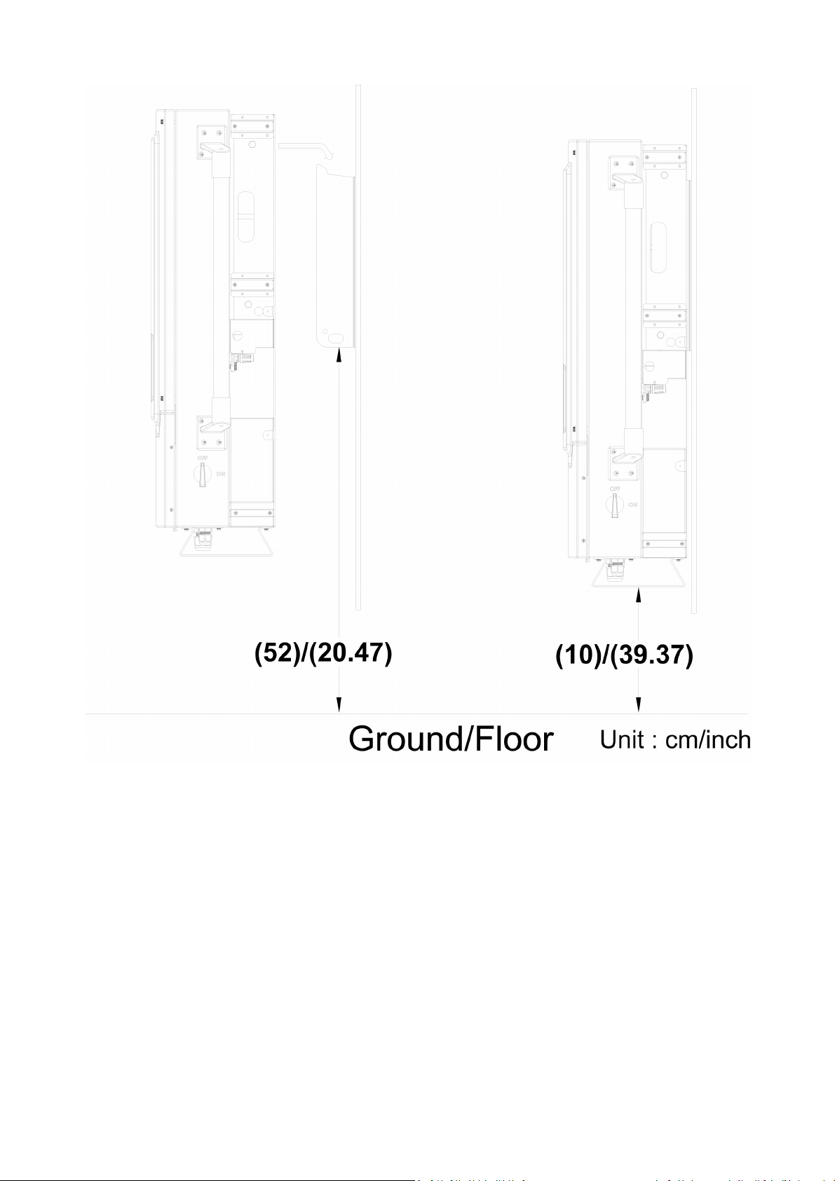
∙ ISMG3 inverters, that must be vertically mounted, can be located indoor or
outdoor according to protection degree of enclosure IP55.
∙ Leave at least 50 cm (19.7 inches) of free space above and 100 cm (39.4
inches) below the inverter when installed outdoor. Allow 20 cm (7.9 inches)
between inverters when installing multiple inverters for better ventilation (see
Fig 2.1.1).
∙ Mount the inverter on a wall that is strong enough to withstand the inverter
with 75 kg weight.
∙ Avoid mounting the inverter on a location directly exposed to sunlight to
maintain the ambient temperature of the inverter within -25° and 60 °C (-13°
and 140°F). Humidity shall be within 0% and 95%.
12
Page 23

WARNING!
Some parts of the cooling surface can reach temperatures over
70°C (158°F) when the inverter is in operation. Do not operate the
inverter where it exposes to flammables, explosive atmospheres or
close to combustibles or unknown materials that may result in
fire/expolsion danger.
WARNING!
Do not expose the inverter to the corrosive liquids and/or gases.
Keep DC wirings as short as possible to minimize power loss.
The mounting bracket should be fastened on a concrete or a masonry wall
with the recommended anchors.
Fig 2.1.1 Clearances required for ISMG3 inverter installation
13
Page 24

2.2 Mounting
The steps listed below describe how to mount the inverter on the wall:
1. After taking out the inverter from the carton, the attached mounting bracket
shall first be removed from the inverter by following the steps shown in Fig
2.2.1 below.
Fig 2.2.1 To remove the mounting bracket from the inverter
14
Page 25

2. Use the mount bracket (Fig 2.2.2) as a template to mark the location of the
holes to be drilled in the wall. After drilling the holes, the mounting bracket is
then held against the wall and fastened to the wall with anchors as shown in
Fig 2.2.3. (At least ten (10) screws required)
For mounting on wooden wall, the suggested diameter of screw is at least
6.35mm and the length is 25.4mm. The nut size needs to be at least 12.7mm.
A minimum of 10 screws are required to mount the bracket on wooden wall
For mounting on steal plate, the suggested screw size is M8x16. A minimum
of 8 screws are required to mount the bracket on steel plate
For mounting on cement wall, the suggested anchor screw with outer
diameter of 8mmx38.1mm is recommended. The nut size needs to be at least
12.7 mm. A minimum of 8 screws are required to mount the bracket on
cement wall
Fig 2.2.2 Inverter mounting bracket
15
Page 26

Fig 2.2.3 Fasten the mounting bracket
16
Page 27
3. Once the mounting bracket is fastened to the wall, the inverter can be
mounted and fastened on the bracket. Hook the inverter on the mounting
bracket flanges and slip down carefully to lock it in place. And then fasten the
inverter to the mounting bracket as shown in Fig 2.2.4.
17
Page 28
18
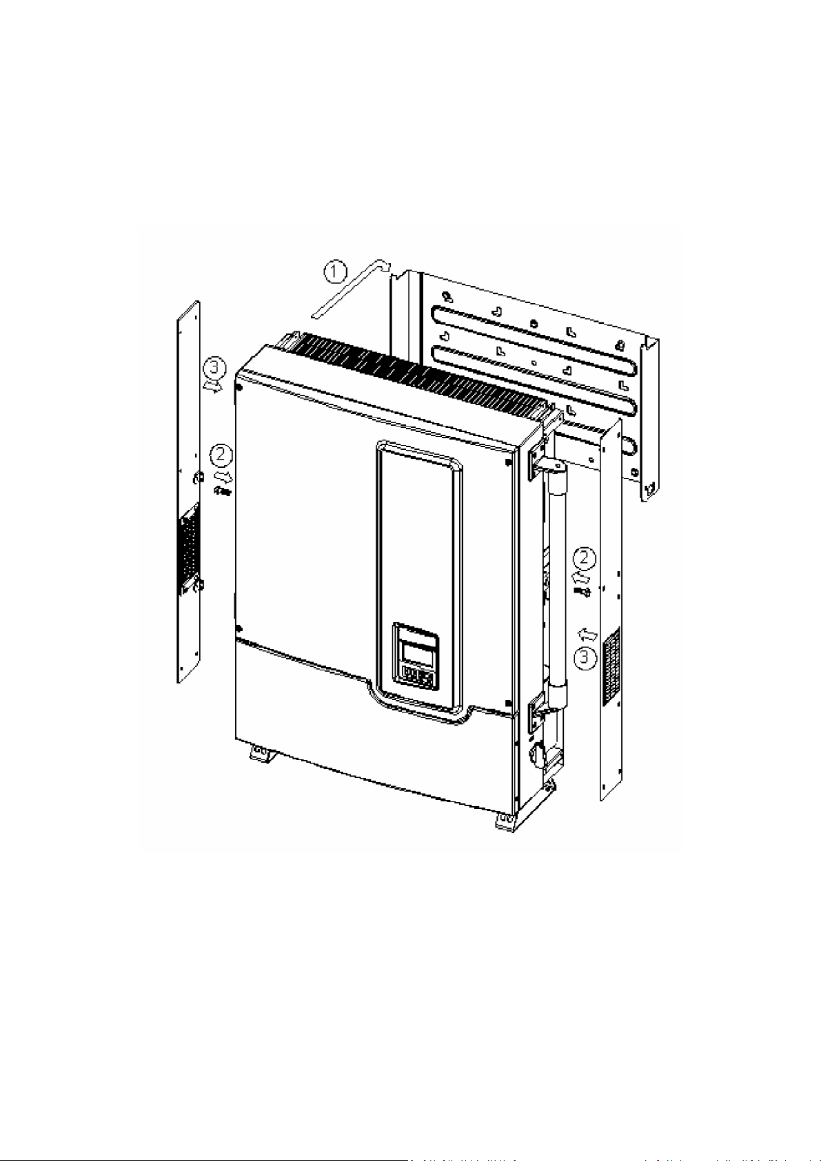
Page 29

Fig 2.2.4 Hook the Inverter on the mounting bracket and then fasten the screw
After the inverter has been hooked correctly on the bracket and fastened to the
mounting bracket, it is then possible to proceed with the wiring.
19
Page 30

2.3 Wiring the inverter
It is necessary to open the front lid of the wiring box before wiring the inverter.
First, the DC disconnect switch must be turned OFF as shown in Fig 2.3.1. And
then remove the two screws on the right hand side; open the red colour front lid
of the wiring box as shown in the Fig 2.3.2 and Fig 2.3.3 below.
Fig 2.3.1 Turn the DC disconnect switch OFF
20
Page 31

Fig 2.3.2 Loosen the screws
21
Page 32

Fig 2.3.3 Open the front lid of the wiring box
After the door is opened, it is then possible to remove the covers of the Threaded
Conduit holes as shown in the Fig 2.3.4 for the DC and AC cables to be put
through the threaded conduit holes in order to connect the inverter.
22
Page 33

Fig 2.3.4 Removal of the covers for the cable through holes
The following three sections describe the wiring for the AC, DC, and
communication ports. The wiring shall carried out in the wiring box for the
ISMG315 and ISMG320. There is a DC terminal block, two (2) RJ-45 connectors,
and one (1) AC terminal block in the wiring box as shown in Figure 2.3.5. The DC
terminal block is used to connect up to two (2) PV strings individually or in parallel
in the wiring box. The RJ-45 connectors are used for external communication to a
remote computer or terminal. The AC terminal block is used to connect to the
utility grid, through a circuit breaker and distribution panel, according to national
and local requirements.
23
Page 34

Fig 2.3.5 Wiring box front view
24
Page 35

WARNING!
All electrical work shall carried out in accordance with the local and
national electrical norms and should follow the important safety
precautions contained in this manual.
WARNING!
Make sure that suitable connecting cables are used for both the AC
and DC wirings. The cable must be adequately dimensioned and
suitably inert to temperature fluctuation, UV radiation and other
possible hazards. For DC wiring connection to the ISMG3 inverter,
use 10 to 16 mm2 (#8 to #6 AWG), 90°C (194°F) copper wire; For AC
wiring connection, use 6 to 10 mm2 (#10 to #8 AWG), 90°C (194°F)
copper wire.
WARNING!
PV arrays will be energized when exposed to light. Cover the arrays
with opaque (dark) material during installation and wiring and make
sure the DC switch is on OFF position (as in fig.2.3.1)
Before wiring the ISMG3 inverter, it is necessary to determine the utility
configuration that the inverter will be connected to. The ISMG315 and ISMG320
inverters shall be used in three-phase utility interconnection with neutral as well
as the ground as shown in Fig 2.3.6.
25
Page 36

Note: When connecting the ISMG3 inverter to the utility, the grid voltage must be
compatible.
Fig 2.3.6 Utility Grid Configuration
26
Page 37

2.3.1 Connection of the AC cable
Use the following procedures to wire the AC cables.
1. Open the Distribution panel and switch off the circuit breaker used to
connect the inverter to the grid.
2. Use 6 to 10 mm2 (#10 to #8 AWG), 90°C (194°F) copper wire for all AC wiring
connections to the ISMG3 inverter.
3. Connect the cable GND to the ground terminal labeled
4. Connect the cable N to the terminal labeled N of the AC terminal block.
or “PE”
.
Fig 2.3.1.1 AC Terminal Block for AC cable connections
5. Connect the cables of the utility grid phases: L1, L2 and L3, to the terminals
labeled “L1”, “L2” and “L3” of the AC terminal block correctly.
6. Tighten the screws with a torque of 3.0 Nm (27.6 lb-in).
7. Reconfirm that all connections have been performed properly as described
above and all screws are properly tightened.
27
Page 38

WARNING!
Make sure that the circuit breaker to the mains utility is switched
OFF before connecting the power cable from the breaker to the AC
terminal block.
WARNING!
Each connection to an ISMG3 inverter must be installed with a
dedicated circuit breaker in the mains utility service panel. The
breaker must be sized in order to handle the rated maximum output
voltage and current of an ISMG3 Inverter. No other appliances may
be connected to the circuit breaker.
28
Page 39

!
!
2.3.2 Connection of the DC cable
The wiring box of the ISMG3 inverter is designed to support up to two (2)
independent PV strings to be connected in the wiring box and then fed into the
inverter.
Fig 2.3.2.1 ISMG3 Inverter supports two (2) independent PV strings
CAUTION!
Overcurrent protection may be required depending on the type
and ratings of the PV module configured in your system. The
maximum DC input current is 43.3A for ISMG315 and 57.8A for the
ISMG320. The maximum DC current allowed per string is 21.6A for
ISMG315 and 28.9A for ISMG320.
CAUTION!
The +PV and –PV cables of a PV sting shall be connected to the DC
terminals labeled “+” and “-” respectively. The capacity of the
cables should be taken into account by system installers to
determine the proper rating of the PV string fuse or a fire hazard
may occur if there is short-circuit in a PV string.
29
Page 40

There are two (2) terminals per PV string located inside the wiring box used for
the DC cable connections. Up to two (2) independent PV strings are supported by
the ISMG3 inverter. Therefore, there are four (4) terminals, two (2) of them are
labeled with “+” and other two (2) are labeled with “-”, in the wiring box for DC
cable connections as shown in Fig 2.3.2.2 and Fig 2.3.2.3. All the screws for the
cable connections shall be tightened with a torque of 3.5 Nm (35.5 lb-in).
Fig 2.3.2.2 PV Inverter Connections
Fig 2.3.2.3 PV Strings in Parallel
30
Page 41

!
!
NOTE: The ISMG3 inverter with Dual-MPP tracker is designed to be applied
to a variety of different configurations. In most cases it is
recommended to link the two PV strings into a single hole to obtain
the highest efficiency. Please consult with your installation servicer
and see how to connect, as show in Fig 2.3.2.3.
CAUTION!
PV arrays are energized when exposed to light. Use safe working
practices when working on PV arrays.
WARNING!
Route the DC cables to be connected to the ISMG3 inverters away
from any possible hazards that could damage the cables.
WARNING!
Hazardous voltage is still present on the ISMG3 inverter after
disconnection of all PV DC inputs. Allow 5 minutes for the device to
discharge the energy completely.
CAUTION!
Make sure that the DC input voltage generated by the PV arrays
must be equal to or less than 850 VDC in any condition, especially
in cold weather conditions, or it will cause damage to the ISMG3
inverter.
31
Page 42

2.3.3 Connection of the Communication cable
The ISMG3 inverter supports two common data interface standards, RS-232 and
RS-485 that will be used to communicate to a remote computer or terminal
equipped with RS-232 or RS-485. Only one of the communication interfaces can
work at a time. As shown in Figure 2.3.3.1, there are two RJ-45 connectors, RJ45-R
and RJ45-L, which are located on the bottom of the enclosure. The pin numbers of
the RJ-45 connectors and the corresponding signals are described in Figure 2.3.3.2
below. If the RS485 is used as the external communication interface and the
inverter is the last device within the RS485 chain connections, then the
termination switch shall be put to ON position (shown in Figure 2.3.3.4). Users
shall open the front lid of the wiring box to switch the termination switch to ON
position. The termination switch is default set to OFF position.
Fig 2.3.3.1 Positions of the communication ports and termination switch
32
Page 43

RJ45-L
Top view
Pin
1 TXD (RS232)
2 RXD (RS232)
18
3 Not used
4 GND
5 GND
6 Not used
7 TX A (RS485)
8 RX B (RS485)
RJ45-R
18
Top view
Pin
1 Factory reserved
2 Factory reserved
3 5V
4 GND
5 GND
6 5V
7 TX A (RS485)
8 RX B (RS485)
Fig 2.3.3.2 RJ-45 Pins and Signals
As shown in Fig 2.3.3.2, the RS-232 signal pins, TXD and RXD, are only on the
RJ45-L. Therefore, only the RJ45-L can be used to connect to the remote PC or
terminal when the RS-232 interface is selected. The cable with the part number of
ISMG-RJ45S0918, which is 180 cm (70.9 inches) in length, is dedicated for the
communications between a ISMG3 inverter and a computer when RS-232
interface is used. This cable has an RJ45 connector on one end and a RS-232 (DB9)
connector on the other end as shown in Fig 2.3.3.3. If RS-485 interface is selected,
then both RJ-45 connectors on the ISMG3 inverter can be used for the cascaded
RS-485 connections shown in Fig 2.3.3.4.
33
Page 44

Fig 2.3.3.3 RS-232 connection (ISMG-45S0918)
Fig 2.3.3.4 RS-485 connection
34
Page 45

2.4 Wiring inverter in parallel
ISMG3 inverters can be connected in parallel when more power is required. In the
parallel configuration, each inverter shall connect to its own PV array. It is not
recommended to connect one PV array to more than one inverter. This may cause
the inverter to work abnormally. The Fig 2.4.1 below shows the connections
between inverters and PV arrays in parallel configuration.
Fig 2.4.1 Parallel configuration of inverter
35
Page 46

3. Operation
voltage point, the inverter is powered up, and enters the
displayed
on the LCD. In this operation mode, the inverter sets the
, and detects all parameters
that will be stored for future use. This stage takes only a few
ter will wait until the DC input
voltage point to enter the
3.1 Overview
The control electronics will be active as soon as the DC (PV) voltage reaches
“minimum MPPT” voltage point which is around 200VDC. The ISMG3 inverter is
then powered up and will show “Illumination” on the LCD, complete the system
initialization and wait for the DC voltage to reach the “PV start” voltage point
which is 400VDC. When the DC voltage reaches the “PV start” voltage point, the
inverter will enter “Checking” mode and then go on-line with the mains grid
(“Grid/MPP” mode) if all necessary conditions for grid connection are checked
and fulfilled. If the DC input voltage falls below the “pre-set threshold” point, the
inverter will shut off its output AC power and go back to “Illumination Low” mode
providing the DC voltage remains above the minimum MPPT voltage point. When
the DC voltage goes under the “minimum MPPT” voltage point, the inverter will
shut down itself.
There are five main operating modes described in detail below.
Illumination: When the DC input voltage goes above the “minimum MPPT”
system initialization procedure with “Illumination”
initial values, runs diagnostics
seconds and then the inver
voltage reaches the “PV start”
“Checking” mode.
36
Page 47

Checking:
In this operation mode, the inverter checks all parameters on
nditions must be fulfilled and last for a certain
period of time, then the system will enter the Grid/MPP
is under
inverter
, turn the display
inverter continues to
to AC
stop
any
detected in the operating mode
on
the
state, stop feeding power to the grid, and then jump
executes a preset sequence. When
a
system fault mode
and enter checking mode. Some faults, like component
ff operation in
malfunction,
both AC and DC sides to ensure that connecting to the mains
is safe. All co
mode. If any parameter, except the DC voltage that
the “PV start” voltage, does not meet the criteria the
goes to “System Fault” mode.
Grid/MPP: The inverter will turn on the AC relays
backlight into green colour, and start feeding the AC power to
the grid. In this operating mode, the
convert the DC power generated by the PV array in
power that is then fed into the grid. The inverter will
feeding the power and go back to checking mode if
conditions for grid feeding mode is not satisfied anymore.
System Fault: When fault(s) occurs and are
described above, the inverter will display “System Fault”
the LCD (the display backlight turns to red) and exit
current
into the fault mode which
the faults have been cleared and do not appear anymore for
preset period of time, the inverter will exit
failure, will cause the inverter going into the “System idle”
mode. This condition requires maintainance sta
order to be cleared.
System Idle: Once the inverter has detected a major fault or
37
Page 48

it will go into the “System idle”
mode and stop feeding the
This state requires
and put the
power to the grid for safety reasons. Normally this is a failure
that cannot be removed by the user.
maintainance staff operation in order to be reset
inverter back to normal operation.
38
Page 49

3.2 Operation Features
1. Anti-Islanding protection
When an “islanding” condition is detected, for instance the utility grid
falls or is disconnected by mean of the mains disconnector, the inverter
will stop feeding the power on the AC output. An “island” is defined as a
grid tied inverter maintaining operation and feeding power to a load that
is isolated from the utility power source. This situation on the ISMG
inverters causes an automatic shutdown of the inverter. This is a safety
feature which is primarily meant to prevent electric shock hazard to
personnel who might have shut down the Utility grid in order to make
maintainance operations on it.
2. Unitary Power Factor:
The ISMG3 inverter intent is to feed the power with a unitary power
factor (PF = 1) to the utility during operation. The inverter continues
sensing the phase of the utility voltage and builds the output current
waveform in phase with the utility voltage.
3. Maximum Power Point Tracking:
In order to find the most efficient way of utilizing the solar energy,
ISMG3 inverters are designed to track and absorb the maximum power
from the PV array. The Maximum Power Point Tracking (MPPT) function
is employed in the embedded control software to achieve this intended
purpose.
39
Page 50

3.3 LCD Display
The ISMG3 inverter has a 128 x 64 graphic LCD Display with three (3) colours
backlight, to display various information of the inverter such as the operating
status/settings, input/output data, cumulated power, and error messages.
furthermore, there is a keypad with 4 pushbuttons for users to select the
information to be displayed on the LCD from one of the categories of “System
Status”, “Energy Production”, and “Error Message”. The User can change, under a
password protected menu, some of the settings by selecting the “Edit Settings”.
As long as the DC input voltage is above the minimum MPPT voltage, the LCD
continues to display the information, the flow is described below in this section.
Fig 3.3.1 Front panel of the ISMG3 inverter
40
Page 51

3.3.1 LCD Backlight Indication
There are three (3) colours: white, green, and red, of LCD backlight. The colour
will change according to the inverter operation status as shown in Figure3.3.1.1.
The explanation of the status and the corresponding colours of the backlight are
described in the following table.
Mode::::Grid/MPP
Mode::::Illumination
Mode::::Illumination
Vac::::230/230/230V
Vac::::230/230/230V
Fac::::50.00Hz
Fac::::50.00Hz
Pac:::: 0W
Pac:::: 0W
03/27 06:50:25
03/27 06:50:25
Mode::::Grid/MPP
Vac::::230/230/230V
Vac::::230/230/230V
Fac::::50.00Hz
Fac::::50.00Hz
Pac::::20000W
Pac::::20000W
03/27 13:50:25
03/27 13:50:25
Fig 3.3.1.1 3 colours LCD backlight
Mode::::SystemFault
Mode::::SystemFault
Vac::::230/230/230V
Vac::::230/230/230V
Fac::::50.00Hz
Fac::::50.00Hz
Pac:::: 0W
Pac:::: 0W
03/27 15:20:45
03/27 15:20:45
LCD Backlight Indication Table
41
Page 52

LCD backlight Operating status Description
White
Green
Initialization
Illumination
Checking
Grid/MPP
Derating Reduce the AC power feeding.
The inverter sets the initial values and
detects all parameters.
The low Sun irradiation can not start
the inverter.
The inverter monitors all the system
parameters.
The Inverter is feeding AC power to the
grid.
The system has encountered a minor
Warning
warning, but it continues to feed the
AC power to the grid.
Red
The inverter has detected a
SystemFault
SystemIdle
Programming The program is being updated.
recoverable failure and will re-start on
its own as soon as normal condition is
restored.
An unrecoverable failure occurred; The
unit requires service personnel in
order to verify the system and restore
normal operation.
42
Page 53

3.3.2 Display messages flow
The display messages flow changes according to the procedure we are into. There
are 3 main operation procedures: regular procedure, fault procedure or idle
procedure.
The regular procedure is when the system goes from power-on (illumination low),
system check, and then Grid/MPPT mode without any fault condition detected. If
during the system check, a fault condition that could be cleared is detected, the
system will turn to the fault procedure. The system will return to regular
procedure as soon as the fault condition disappears. An example of this situation
could be the “island” condition: if the grid voltage goes off and then after some
time goes on again, the ISMG3 goes into fault state, but the fault condition is
cleared when the power returns. If a fault cannot does not self restore, the
system will enter the idle procedure and will need a service staff to clear the fault
and reset the system. The following paragraphs explain how the display works in
the different operating modes.
Illumination:
When the DC input voltage rises above the “minimum MPPT” voltage point but
under the “PV start” voltage point, the ISMG3 inverter is powered up and will
show the model name (e.g. ISMG315), serial number, firmware versions, and the
complied standards, on the Display. After around five (5) seconds, the Main Menu
with four (4) selections, System Display, Graphic Method, Error message, and
Setting, that user can select through the up/down buttons will be displayed on
the LCD. Three seconds later, if no selection is made, the “System Display” will
automatically go to “Illumination” Mode on the LCD and stop there until the
system goes into the “Checking” mode. Together with the Mode (Illumination),
43
Page 54

the LCD also displays the three-phase AC voltages, Frequency, and AC output
DK5940
DK5940
power on the AC side.
PVMate 20E
PVMate 20E
S/N::::020010070001
S/N::::020010070001
Ver. M00 & S00
Ver. M00 & S00
Std.
Std.
5 seconds ↓
System Display
System Display
System Display
Graphic Method
Graphic Method
Graphic Method
Error message
Error message
Error message
Setting
Setting
Setting
3 seconds ↓
Mode::::Illumination
Mode::::Illumination
Vac::::230/230/230V
Vac::::230/230/230V
Fac::::50.00Hz
Fac::::50.00Hz
Pac:::: 0W
Pac:::: 0W
03/27 23:50:25
03/27 23:50:25
44
Page 55

Checking:
When the DC input voltage reaches the “PV start” voltage point, the inverter goes
into the “Checking” Mode. In this operation mode, the inverter will check “Riso”,
all parameters on both AC and DC sides, and then the AC relay to ensure that
connecting to the mains is safe. After all conditions are satisfied for a preset time,
which can be set from 20 to 600 seconds, then the system will enter the
Grid/MPP mode and feed AC power to the grid. During the Checking mode, the
display will follow the information flow as shown in the diagram below.
Mode::::Check 300s
Mode::::Check 300s
Mode::::Check Riso
Mode::::Check Riso
Mode::::Check Riso
Vac:::: 0/ 0/ 0V
Vac:::: 0/ 0/ 0V
Vac:::: 0/ 0/ 0V
Mode::::Check 300s
Vac::::230/230/230V
Vac::::230/230/230V
Vac::::230/230/230V
Fac::::00.00Hz
Fac::::00.00Hz
Fac::::00.00Hz
Pac:::: 0W
Pac:::: 0W
Pac:::: 0W
03/27 23:50:25
03/27 23:50:25
03/27 23:50:25
30 seconds ↓
30 seconds ↓
Mode::::Checking
Mode::::Checking
Mode::::Checking
Vac::::230/230/230V
Vac::::230/230/230V
Vac::::230/230/230V
Fac::::50.00Hz
Fac::::50.00Hz
Fac::::50.00Hz
Pac:::: 0W
Pac:::: 0W
Pac:::: 0W
03/27 23:50:25
03/27 23:50:25
03/27 23:50:25
3 seconds ↓
3 seconds ↓
Fac::::50.00Hz
Fac::::50.00Hz
Fac::::50.00Hz
Pac:::: 0W
Pac:::: 0W
Pac:::: 0W
03/27 23:50:25
03/27 23:50:25
03/27 23:50:25
XXX seconds ↓
XXX seconds ↓
Mode::::Check Relay
Mode::::Check Relay
Mode::::Check Relay
Vac::::230/230/230V
Vac::::230/230/230V
Vac::::230/230/230V
Fac::::50.00Hz
Fac::::50.00Hz
Fac::::50.00Hz
Pac:::: 0W
Pac:::: 0W
Pac:::: 0W
03/27 23:50:25
03/27 23:50:25
03/27 23:50:25
3 seconds ↓
3 seconds ↓
45
Page 56

Grid/MPP:
After the system has entered into the Grid/MPP (grid feeding) mode, the inverter
will feed the AC power to the mains grid and show on the display, with green
lolour backlight, the operating mode, the actual AC voltage, frequency, and. The
other data such as the cumulated energy, the DC input power of each PV string,
and the AC output power of each phase, can be displayed on the LCD by press the
“DOWN” button of the keypad as shown in the figure below.
By using the “UP”, “DOWN”, “ESC”, and “OK” buttons, users may be able to view
the data they want.
(a)Press “UP” or “DOWN” key to select the monitoring parameter.
(b)Press “ESC” key return to previous state.
(c)Press “OK” key to confirm.
46
Page 57

Mode::::Grid/MPP
Mode::::Grid/MPP
Mode::::Grid/MPP
Vac::::230/230/230V
Vac::::230/230/230V
Vac::::230/230/230V
Fac::::50.00Hz
Fac::::50.00Hz
Fac::::50.00Hz
Pac::::20000W
Pac::::20000W
Pac::::20000W
03/27 23:50:25
03/27 23:50:25
03/27 23:50:25
Enter “ DOWN ” key ↓
Enter “ DOWN ” key ↓
Mode::::Grid/MPP
Mode::::Grid/MPP
Mode::::Grid/MPP
Eac_ty:::: 999kWh
Eac_ty:::: 999kWh
Eac_ty:::: 999kWh
Eac_to::::999999kWh
Eac_to::::999999kWh
Eac_to::::999999kWh
CO2_rd::::999999kg
CO2_rd::::999999kg
CO2_rd::::999999kg
03/27 23:50:25
03/27 23:50:25
03/27 23:50:25
Enter “ DOWN ” key ↓
Enter “ DOWN ” key ↓
Mode::::Grid/MPP
Mode::::Grid/MPP
Mode::::Grid/MPP
VPV_A:::: 630.0 V
VPV_A:::: 630.0 V
VPV_A:::: 630.0 V
I PV_A:::: 18.2 A
I PV_A:::: 18.2 A
I PV_A:::: 18.2 A
WPV_A::::11466 W
WPV_A::::11466 W
WPV_A::::11466 W
03/27 23:50:25
03/27 23:50:25
03/27 23:50:25
Enter “ DOWN ” key ↓
Enter “ DOWN ” key ↓
Mode::::Grid/MPP
Mode::::Grid/MPP
Mode::::Grid/MPP
Vac_L1::::230.0 V
Vac_L1::::230.0 V
Vac_L1::::230.0 V
I ac_L1:::: 31.8 A
I ac_L1:::: 31.8 A
I ac_L1:::: 31.8 A
Pac_L1:::: 7314 W
Pac_L1:::: 7314 W
Pac_L1:::: 7314 W
03/27 23:50:25
03/27 23:50:25
03/27 23:50:25
Enter “ DOWN ” key ↓
Enter “ DOWN ” key ↓
Mode::::Grid/MPP
Mode::::Grid/MPP
Mode::::Grid/MPP
Vac_L2::::230.0 V
Vac_L2::::230.0 V
Vac_L2::::230.0 V
I ac_L2:::: 31.7 A
I ac_L2:::: 31.7 A
I ac_L2:::: 31.7 A
Pac_L2:::: 7291 W
Pac_L2:::: 7291 W
Pac_L2:::: 7291 W
03/27 23:50:25
03/27 23:50:25
03/27 23:50:25
Enter “ DOWN ” key ↓
Enter “ DOWN ” key ↓
Mode::::Grid/MPP
Mode::::Grid/MPP
Mode::::Grid/MPP
VPV_B:::: 630.0 V
VPV_B:::: 630.0 V
VPV_B:::: 630.0 V
I PV_B:::: 18.2 A
I PV_B:::: 18.2 A
I PV_B:::: 18.2 A
WPV_B::::11466 W
WPV_B::::11466 W
WPV_B::::11466 W
03/27 23:50:25
03/27 23:50:25
03/27 23:50:25
Enter “ DOWN ” key ↓
Enter “ DOWN ” key ↓
47
Mode::::Grid/MPP
Mode::::Grid/MPP
Mode::::Grid/MPP
Vac_L3::::230.0 V
Vac_L3::::230.0 V
Vac_L3::::230.0 V
I ac_L3:::: 31.9 A
I ac_L3:::: 31.9 A
I ac_L3:::: 31.9 A
Pac_L3:::: 7337 W
Pac_L3:::: 7337 W
Pac_L3:::: 7337 W
03/27 23:50:25
03/27 23:50:25
03/27 23:50:25
Page 58

Derating:
When power de-rating is detected, the “Derating” message will be displayed on
the LCD as shown in the picture below. There are five possible situations that may
cause output power derating. The ISMG detects only one derating situation at the
time. Therefore, users shall also view other information through the RS485
interface if they want to precisely identify the reason that causes derating, when
the “Derating” message is displayed. Please refer to Section 4.3 De-rating
Operation for additional information regarding the situations that can cause
power derating. The VDE0126 requires that if the maximum AC output power
(110% of the rated power can normally occur together with VacH) lasts for 10
minutes, the inverter shall shut off the output. In the ISMG315/320 inverter, it is
designed to lower the output power (output power de-rating) before shutting off
the output. If the VacH message goes away, the inverter will not turn off the
output. If the VacH message remains, the inverter will shut off its output
according to the VDE0126 norm.
Mode::::Derating
Mode::::Derating
Vac::::230/230/230V
Vac::::230/230/230V
Fac::::50.00Hz
Fac::::50.00Hz
Pac::::16888W
Pac::::16888W
03/27 13:50:25
03/27 13:50:25
48
Page 59

Warning:
There are three possible warning messages that can be displayed on the Display
when exespected situations occur in Grid/MPP mode:
When the system has encountered a problem in accessing to the
internal EEPROM memory device, the “EEPROM” warning message
will be displayed
The ISMG3 has encountered a communication error with the
external terminal, the “COMM” warning message will be displayed
on the LCD;
If one and/or two o the built-in fans stop running, the warning
message, Fan Lock A, Fan Lock B or Fan Lock AB, will be displayed. If
all warnings occur simultaneously, the warning messages will be
displayed in the following order with three (3) seconds interval:
COMM => EEPROM => Fan Lock A (or B or AB)
Mode::::Fan Lock AB
Mode::::Fan Lock AB
Vac::::230/230/230V
Vac::::230/230/230V
Fac::::50.00Hz
Fac::::50.00Hz
Pac::::16888W
Pac::::16888W
03/27 13:50:25
03/27 13:50:25
49
Page 60

System Fault:
When the system goes into the fault mode, it will shut off the output AC power,
disconnect from the mains grid, and have the “System Fault” message displayed
on the LCD with the backlight in red color as shown in the figure below. The
fault(s) that cause the system going into the fault mode will be recorded. Users
can press the “ESC” button to go into the main menu and then select the “Error
message” to view the error message(s) of the fault(s). Users may refer to the Error
Message Table on Section 3.6 for the explanations of the error messages. When
the fault will clear, the inverter will automatically try to go into the Checking
mode and then the Grid/MPP mode to feed AC power to the grid.
50
Page 61

System Idle:
When the ISMG3 inverter goes into the Idle mode, only service staff can clear this
mode and reset the inverter. When in the idle mode, the ISMG3 inverter will shut
off the output AC power, disconnect from the mains grid, and have the “System
Idle” message displayed on the LCD with the backlight in red color as shown in the
figure below. The fault(s) that cause the system going into the idle mode are
recorded. Users can press the “ESC” button to go into the main menu and then
select the “Error message” to view the error message(s) of the fault(s). Please
refer to Error Message Table on Section 3.6 for explanations of error messages.
51
Page 62

2
3.3.3 Produced Power Graphs
Press the “ESC” button to return to the main menu, then press the “Down” key
until the “Graphic Method” is highlighted and then press the “OK” key to confirm
the selection.The daily production graph will be displayed on LCD as shown in the
figure below. This trend graph shows the output AC power produced on a
specified date. The date is indicated on the upper right corner. In order to go to
another date press the “OK” button first and then press the “DOWN” or “UP” until
the required date is reached. The ISMG3 inverter has enough memory to record
the daily chart for up to 31 days.
System Display
System Display
System Display
Graphic Method
Graphic Method
Graphic Method
Error message
Error message
Error message
Setting
Setting
Setting
Press “OK” key ↓
kWh
kWh
kWh
kWh
5
5
5
5
5
5
4
4
4
4
4
4
3
3
3
3
3
3
2
2
2
2
2
2
1
1
1
1
1
1
2 4 6 8 10 12 14 16 18 20 22 24
2 4 6 8 10 12 14 16 18 20 22 24
2 4 6 8 10 12 14 16 18 20 22 24
2 4 6 8 10 12 14 16 18 20 22 24
2 4 6 8 10 12 14 16 18 20 22 24
2 4 6 8 10 12 14 16 18 20 22 242 4 6 8 10 12 14 16 18 20 22 24
07/31
07/31
07/31
07/31
Press “DOWN” key ↓
5
Page 63

If order to display the monthly chart, first press “ESC” key and then press the
"DOWN" key to change to the monthly chart as shown below.
On the upper right
corner, it shows the present month. To change month press “OK” first and then
press “DOWN” or “UP” key to switch the months. The ISMG3 may record monthly
charts for up to 12 months.
kWh
kWh
200
200
200
150
150
150
100
100
100
50
50
50
kWh
10 20 30
10 20 30
10 20 30
2010/07
2010/07
2010/07
53
Page 64

3.3.4 Error Messages
To review the recorded error messages, users shall select "Error Message", on the
main screen, by pressing the “Down” or “Up” key from and then press the "OK"
key to confirm. The LCD will then display the last error message recorded on the
LCD with the date and time that the fault occurred. To see the next recorded error
message, press “DOWN” or “UP” key to browse through the pages. The ISMG3
may record up to 99 error messages in the memory.
System Display
System Display
System Display
Graphic Method
Graphic Method
Graphic Method
Error message
Error message
Error message
Setting
Setting
Setting
Press “OK” key ↓
1. 2010 / 07 / 01
1. 2010 / 07 / 01
17::::45::::35
17::::45::::35
Error message
Error message
Press “DOWN / UP” key
54
Page 65

3.3.5 Setting Operation
Some of the Inverter parameters can be re-configured from the built in panel. To
chenge the paramaters select "Setting" from the main menu and then confirm by
pressing the "OK", as shown below. The standard selection is password protected.
The other settings such as the date, time, language, minimum start voltage,
start-up time, buzzer ON/OFF, communication baud rate, and RS485 address, are
not password protected. The interface protection standard change: DK5940,
VDE 0126, or RD1663, shall be carried out by qualified and professional service
staff. For this purpose a specific password ie required. When the setting change is
completed, the inverter must be restarted to have the new settings effectively
executed.
The parameters that can be re-configured from the panel are described as
follows:
Date: Date setting.
Time: Time setting.
Language: Display language selection.
Start V: Adjust the minimum startup voltage.
Start Sec: Set the delay time at start-up.
Alarm: Turn "ON" or "OFF" the buzzer.
Standard: Interface protection standard setting according to
local/national requirements.
Baudrate: Set the communication serial port baud rate.
RS485 Addr: Set the RS485 address.
Auto Test: Perform auto-test function. (Only for ISMG315IT and
ISMGT320IT)
55
Page 66

System Display
DK5940
YES
DK5940
DK5940
YES
YES
System Display
System Display
System Display
Graphic Method
Graphic Method
Graphic Method
Graphic Method
Error message
Error message
Error message
Error message
Setting
Setting
Setting
Setting
Press “ OK ” key ↓
Press “ OK ” key ↓
System Setting
System Setting
System Setting
Password:::: 000000
Password:::: 000000
Password:::: 000000
Press “UP/DOWN/OK” key ↓
Press “UP/DOWN/OK” key ↓
System Setting
System Setting
System Setting
Standard:
Standard:
Standard:
Baudrate:::: 9600
Baudrate:::: 9600
Baudrate:::: 9600
RS485 Addr.:::: 250
RS485 Addr.:::: 250
RS485 Addr.:::: 250
Press “UP/DOWN/OK” key ↓
Press “UP/DOWN/OK” key ↓
System Setting
System Setting
System Setting
Auto Test::::OFF
Auto Test::::OFF
Auto Test::::OFF
Press “ ESC ” key ↓
Press “ ESC ” key ↓
:
:
:
::
::
::
System Setting
System Setting
System Setting
Date::::2010/07/01
Date::::2010/07/01
Date::::2010/07/01
Time:::: 15:25:35
Time:::: 15:25:35
Time:::: 15:25:35
Language::::English
Language::::English
Language::::English
Press “UP/DOWN/OK” key ↓
Press “UP/DOWN/OK” key ↓
System Setting
System Setting
System Setting
Start V :::: 400.0V
Start V :::: 400.0V
Start V :::: 400.0V
Start Sec:::: 300S
Start Sec:::: 300S
Start Sec:::: 300S
Alarm::::OFF
Alarm::::OFF
Alarm::::OFF
Press “UP/DOWN/OK” key ↓
Press “UP/DOWN/OK” key ↓
EXIT Setting:
EXIT Setting:
EXIT Setting:
Press “DOWN/OK” key
Press “DOWN/OK” key
:
:
:
::
::
::
56
Page 67

3.4 Auto Test (Only for ISMG315IT and ISMGT320IT)
This Auto Test function is required according to the Italian Standard DK5940. With
the Auto Test function, users may be able to verify the AC voltage and frequency
(grid side) monitoring function. When the Auto Test function is running, the
inverter will not provide AC power to the mains grid. The Auto Test routine shall
be in the order as:
Maximum AC voltage threshold test for each phase
Minimum AC voltage threshold test for each phase
Maximum AC frequency threshold test for each phase
Minimum AC frequency threshold test for each phase
PVMate 15E/20E
3-phase AC output
R
DC input
Main relay
S
T
There are two relays series connected for each phase of the AC output as shown
above. The Main relay will be closed (activated) when running each threshold test
for each phase. After the threshold test is complete the Main relay will be
released (de-activated). The Auto Test functionality and procedure is described in
the following sections.
57
Page 68

3.4.1 Auto test PC Software
The Auto Test software as an accessory provided with the inverter and should be
installed in a computer which is connected to the inverter through the “RJ45-L
port” (the RJ45 port on the left-hand side of the Inverter). Once the software is
installed successfully, the .EXE file “ISMG315/320 Auto Test” has been created in
the sub-directory “Start\Programs menu”. Users may start the Auto Test function
by double clicking “ISMG315/320 Auto Test.exe” file . The program starts with a
search routine for all inverters connected to the computer, a pop-up window will
appear on the PC screen: “Search for inverters” as shown in Figure 3.4.1.1. If no
inverters are found, the “Search again” warning message will be displayed on the
screen. A re-confirm that the connections are correct within the RS485
communication loop is required. Then click on the “Search for inverters” button
to search again. If at least one inverter is found, the serial number and the status
of the inverter will be shown on the screen as shown in Figure 3.4.1.2.
Fig 3.4.1.1 Search for inverters
58
Page 69

Fig
3.4.1.2 Communicated successfully
Only one inverter at the time can be selected to run the Auto Test function even if
more than one inverter is found. Users can choose the inverter by highlighting the
serial number and then click the “Start Auto Test” button to run the Auto Test
function, which will be performed in the order as shown in Figure 3.4.1.3 and
described below.
a. Maximum AC voltage (VacH) threshold ( phase order: R → S → T )
b. Minimum AC voltage (VacL) threshold ( phase order: R → S → T )
c. Maximum AC frequency (FacH) threshold ( phase order: R → S → T )
d. Minimum AC frequency (FacL) threshold ( phase order: R → S → T )
The standard threshold values and the trip time related to the specified sub test,
will be displayed on the PC screen, before the Auto Test starts. The slew rate of
the threshold values, either increase or decrease, are ≤ 0.05 Hz/s for frequency
and ≤ 1 V/s for voltage starting from the maximum (or minimum) threshold value.
During the Auto Test the threshold value changes linearly and the measured
59
Page 70

voltage or frequency of the AC grid will be displayed on the PC screen. The
maximum/minimum threshold values and the accepted trip time defined in
DK5940 are as follows:
a. Maximum AC voltage threshold: 270 V; < 80 ms
b. Minimum AC voltage threshold: 188 V; < 160 ms
c. Maximum AC frequency threshold: 50.25 Hz; ≤ 60 ms
d. Minimum AC frequency threshold: 49.25 Hz; ≤ 80 ms
The threshold value will decrease (or increase) from the maximum (or minimum)
threshold value toward the measured value of the AC grid. When the threshold
value reaches the measured AC voltage or frequency of the grid the inverter will
disconnect the AC line by de-activate the Main relay. The inverter will measure
the time duration when the command has been sent and the disconnection is
recognized. This time duration must be less than the trip time defined.
(a)
Start Auto-test
60
Page 71

(b) Auto-test completed
Fig 3.4.1.3 Auto-test process
After all sub tests are completed, a popup window “All tests are finished” will
appear on the PC screen and the “OK” key, on the PC screen, has to be pressed in
order to stop the Auto Test software.
61
Page 72

3.4.2 Use Self-testing
It is also possible to run the Auto Test function without a computer connected.
From the main display menù, select “Setting” and then select “Auto Test” and
press “OK” to perform the Auto Test function as shown below. (Please refer to
Section 3.3.5)
System Setting
System Setting
Auto Test::::ON
Auto Test::::ON
Press “ OK “ key ↓
AUTO TEST
AUTO TEST
. . . . . . . .
. . . . . . . .
When the Auto Test function starts running, the “AUTO TEST” message will be
displayed on the Display as shown above and stay until the Auto Test function
ends with “PASS” or “FAIL” message on the display. If the test fails, it will also
show the tested item which didn’t pass the threshold test.
AUTO TEST
AUTO TEST
AUTO TEST
AUTO TEST
<< FAIL >>
<< FAIL >>
<< PASS >>
<< PASS >>
L1 Vac High
L1 Vac High
or
62
Page 73

!
!
CAUTION!
If any one of these sub tests fails, the inverter will go into the “fault
mode” and stop the test. The inverter will stay in “fault mode” and
will not restart unless the test is re-run and it is Passed
CAUTION!
The only purpose of the Auto Test function is only to check the
operation of the interface protection functionality of the inverter.
It will NOT change any actual threshold and trip setting.
63
Page 74

3.5 Error Messages description
when a fault occurs, the inverter will stop feeding the AC power to the utility grid
and display the error message on the LCD. Qualified service staff shall analyse,
measure, and if needed proceed with debugging, according to the error message,
in order to restore normal operation. It is recommended to screen out the fault
condition(s) by referring to the table below and then remove the fault
condition(s) to have the inverter back to normal condition and continue to feed
AC power to the utility. Please contact Carlo Gavazzi local National Sales
Company, your distributor or service representative if the same error message
persists.
64
Page 75

Error Messages Table
Error Message Description
GridNA No AC voltage is detected on the utility grid side.
VacH The AC voltage of utility grid is over the upper limit.
VacL The AC voltage of utility grid is under the lower limit.
FacH The AC frequency of the utility grid is over the upper limit.
FacL The AC frequency of the utility grid is under the lower
limit.
Phase Loss One or two phases are missing (AC voltage is not present
on that / those phase).
L2, L3 Swap. L2 and L3 phases are reversed.
Drift Fac Islanding is detected.
FastEarthCurrent The drastic change of the leakage current has been
detected.
SlowEarthCurrent The leakage current has exceeded a safe operating limit.
DCInjectCurH The DC current injected into the AC grid is over the upper
limit.
Iac_Max. Over current on the grid side.
IacH The AC current is over the upper limit.
65
Page 76

Error Message Description
Riso Low The insulation resistance between PV array and the ground
is below the safe operating limit.
VpvH The DC voltage of PV array is over the upper limit.
IpvH Over current on the DC side.
PpvH Over power on the DC side.
VdcbusH Internal DC bus voltage is over the upper limit.
VdcbusL Internal DC bus voltage is below the lower limit.
Temp. High The internal temperature of the inverter exceeded the safe
operating limit.
CPUs diff.High Internal measurements from both CPU’s are differ from
System Error General system failure.
Relay Open
each other.
Relay Short
Relay Fault
Vdcbus Fault DC/DC converter failure.
Output relay failure.
66
Page 77

Error Message Description
RCMU Fault Leakage current measurement device failure.
I/P HCT Fault
O/P HCT Fault
HCT Fault
Idc-inj. Fault DC injection current monitoring function failure.
SPI Error Internal communication failure.
EEPROM Fault
FanLock_A
FanLock_B
EEPROM test failed. *warning message
Cooling fan / fans stopped running. *warning message
Input/Output current sensor failure.
Comm. Error External communication failed. *warning message
Offset Fault Internal reference voltage failed, +1.5VA, +1.5VB.
CalDataLoss Loss of the Calibration data.
Model Error The hardware MODEL and the CPU software versions are
not compatible.
Version Error The firmware version is not correct.
67
Page 78

3.6 Troubleshooting
The error message(s) are displayed on the LCD and recorded in memory when the
ISMG3 inverter has encountered a fault situation. Some critical faults will cause
the inverter to automatically shut off the output AC power. For safety reason, the
inverter will not re-start until the fault will be cleared. In general, we suggest to
follow the steps described below to identify and solve the problems.
1. Make sure that the ISMG3 inverter is correctly connected to the mains utility
and PV arrays following the connection procedures described in this manual.
2. Try to identify and solve the problem based on the troubleshooting table
below.
3. If the problem cannot be identified and solved, please contact your local
Carlo Gavazzi National Sales Company, distributor or service representative
for assistance.
68
Page 79

Trouble Shooting Table
Restart the inverter again;
Inform professional service
staff if failure does not
Error Message
Comm. Error
DCInjectCurH
Possible Causes
External communication
malfunction
Calibration parameters
are deviated
Internal circuits
malfunction
AC current sensor
malfunctions
The default settings are
Disposal Measures
Restart the inverter again;
Inform professional service
staff if failure does not
restore
Inform professional service
staff in order to check the
calibration parameters CPUs diff.High
restore
Inform professional service
inappropriate
staff to check the settings
69
Page 80

Error Message
EEPROM Fault
FanLock_A
FanLock_B
FastEarthCurrent
SlowEarthCurrent
Possible Causes
EEPROM's parameters
are unrecognized
Fan malfunction
DC or AC wires
insulation is damaged
and it causes high
ground fault current
AC feed lines are
Disposal Measures
Inform professional
service staff to update
the EEPROM's
parameters
Inform professional
staff to replace the fan
Check the DC and AC
wire insulation
Check the AC wirings
GridNA
(Loss of Mains)
HCT Fault
Iac_Max.
IacH
disconnected
AC switch/breaker is
open
Grid power blackout
DC or AC current sensor
malfunctions
Mains voltage drops
suddenly
The inverter
malfunctions
Close the AC switch/
breaker after clearing
the faults
Wait until the grid is
restored
Restart the inverter;
Inform prof. staff if
failure does not restore
If seldom occurring it
can be ignored
Inform professional
staff if failure does not
restore
70
Page 81

;
Inform professional staff if
at least
Error Message
Idc-inj. Fault
Offset Fault
L2, L3 Swap.
Model Error
Phase Loss
RCMU Fault
Possible Causes
Internal circuit
malfunctions
L2 and L3 cables are wired
reversed
Default settings are wrong
One of the AC wirings is
disconnected
Residual current
protective device
malfunctions
Disposal Measures
Restart the inverter again;
Inform professional staff if
failure does not restore
L2 and L3 wirings shall be
swapped
Inform professional staff to
replace the inverter
Check the AC wirings
Restart the inverter again
Relay Open
Relay Short
Relay Fault
Riso Low
SPI Error
Temp. High
AC relay malfunctions
Moisture or conductive
matter between DC lines
and earth.
Internal communication
malfunctions
Insufficient Air circulation
failure does not restore
Remove matter and or dry
the wet area then restart
the inverter again
Restart the inverter again
and Inform professional
staff if failure does not
restore
Allow a clearance of
20cm at least from walls or
other devices for air intake
71
Page 82

and exhaust
Inform
Error Message
VacH
VacL
FacH
FacL
(Mains voltage or
frequency is
beyond the limit)
Ambient temperature is
too high
Possible Causes
AC voltage or
frequency exceeds
the default settings
Mains voltage or
frequency is unstable
The settings are
Ensure the ambient
temperature is below 60°C
Disposal Measures
Wait until the grid is back to
stable condition
Request the utility supplier to
improve and then inform
professional staff to change
the settings.
Inform professional staff to
VdcbusH
VdcbusL
Vdcbus Fault
Version Error
VpvH
IpvH
PpvH
inappropriate
The inverter
malfunctions
Firmware version is
incompatible
PV array voltage
exceeds the
permissible value
check the settings.
Restart the inverter and
professional staff if failure
does not restore
Reinstall the firmware
according to the instruction
Disconnect the DC source and
inform the system installer to
check the configuration of PV
arrays
72
Page 83

4. Technical Documentation
4.1 Outline Drawing
Fig 4.1.1 Outline Drawing of ISMG3
73
Page 84

4.2 Efficiency
The efficiency of the ISMG315/320 is shown in Figure 4.2.1 and Figure 4.2.2
below.
Fig 4.2.1 Efficiency of the ISMG320 = 96.0%
Fig 4.2.2 Efficiency of the ISMG315 = 95.5%
74
Page 85

4.3 De-rating Operation
Here below are described the different situations in which the Inverter will limit
the output power in order ensure the system operates in a safe condition.
Temperature
The ISMG3 inverter monitors the heat sink temperature. If the temperature
exceeds 70°C (ambient temperature is around 45°C), the the output power
will be reduced until the temperature falls under the critical value. The ISMG3
inverter will shut down the AC power output to the grid if the temperature
reaches 85°C. If this situation occurs frequently, it is necessary to check
whether the inverter is installed in an adequate location, with good
ventilation and not exposed to direct sunlight.
Fig 4.3.1 Temperature de-rating curve of the ISMG320
75
Page 86

Input DC current excess
When the input current from the PV strings is about to exceed the maximum
value, the ISMG3 inverter will limit it to the safe operating value in order to
prevent damages to the inverter. If this situation occurs frequently, it is
necessary to check whether the PV arrays are properly configured according
to the Inverter DC current limit.
Fig 4.3.2 DC Power curve of the independent PV string of the ISMG320
Output AC power excess
The maximum power that the ISMG3 inverter feeds to the grid is limited
according to the specifications listed in Section 1.2. The Output current of is
limited by the ISMG3 inverter is in case the AC voltage becomes too high in
ordet to maintain the power within the specified limit.
76
Page 87

Output AC current
The maximum current that the ISMG3 inverter feeds to the grid is limited
according to the specifications listed in Section 1.2.
Fig 4.3.3 Output Power v.s. Grid voltage of the ISMG320
77
Page 88

4.4 MPP Efficiency
The ISMG315/320 supports up two (2) PV strings that can be either connected in
parallel, feeding into a single MPP tracker, or connected individually to each MPP
tracker. The efficiencies of the 2 configurations: two(2) PV strings connected in
parallel and connected individually are shown in Figure 4.4.1 and Figure 4.4.2
respectively.
Fig 4.4.1 MPP Efficiency of the two PV strings in parallel
Fig 4.4.2 MPP Efficiency of the two PV strings in individual
78
Page 89

WARNING!
PV arrays are always energized when exposed to light therefore
hazardous voltage is still present on the terminal blocks and the PV
string fuse holders even the DC disconnect switch is switched OFF.
Please cover the PV arrays with opaque (dark) materials during the
inverter removal. Keep covered until the inverter is hooked back
and reconnected.
WARNING!
Hazardous voltage is still present on the device after disconnection
of all PV DC inputs. Allow 5 minutes for the inverter to discharge
the energy completely.
WARNING!
Check that all DC and AC switches are turned off for at least five (5)
minutes before opening the front covers of the inverter and the
wiring box and disconnect the DC and AC wires between them. The
wires that have been disconnected shall be wrapped with an
insulated material in order to prevent electrical shocks of the
service personnel and to avoid short circuits.
WARNING!
Not to keep any spare parts inside the wiring box.
79
Page 90

5. Warranty information
Warranty Period
A period of 5 years is warranted from the date of your purchase of the ISMG3
series Products.
Additional 5 years warranty: warranty extension up to 10years can be purchased
separately within the term specified in the “warranty terms certificate” from
purchase date of the unit
Warranty Terms
The warranty terms of the ISMG3xx Inverters are specified in the “Warranty terms
and certificate” leaflet enclosed in the package of purchased unit.
Product Return Procedure
The product return procedure and terms are described in the “Warranty terms
and certificate” leaflet enclosed in the package of purchased unit.
On-site Inspection & Repair
The on-site Inspection & Repair procedure and terms are described in the
“Warranty terms and certificate” leaflet enclosed in the package of purchased
unit.
80
Page 91

Your Notes :
81
 Loading...