

CARLO GAVAZZI ISMG 315, ISMG 320 User Manual

User Manual
ISMG 315 / ISMG 320
Three-Phase Solar Inverter

© 2010 Carlo Gavazzi Automation All rights reserved V 1.3 July 2010
2

Safety
KEEP THESE INSTRUCTIONS FOR FUTURE REFERENCE – This manual contains
important instructions for Models ISMG 315 and ISMG 320 that shall be followed
during installation and future maintenance of the ISMG inverter.
Safety Precautions/Safety Notes
Only trained skilled and qualified electrical personnel shall carry out e electrical
installation, wiring, opening of the ISMG inverters. Even when no external voltage
is present, or the device is disconnected, the ISMG inverters can still store high
voltages and cause of electric shocks.
The temperature of the external heat sinks of the device can reach over 70°C
(158°F) in normal operation (Ambient temperature rating: 45°C / 113°F). There is
high risk of burn injury if these parts are touched.
The following general safety precautions must be observed during all operation
phases, service and installation of this device. Failure to comply with these safaty
precautions or specific warnings, elsewhere in this manual, violates safety
standards of design, manufacture, and intended use of the device. The
manufacturer assumes no liability for the customer’s failure to comply with these
requirements.

Safety Symbols
safety information prevent serious injuries or death to users
!
To reduce the risk of injury and to ensure the continued safe operation of this
product, the safety related information, contained in this manual are marked with
the below listed signs.
Warning, risk of electric shock
These
and/or installers.
Earth ground symbol
Caution
These information prevent damage to the product.
Intended Use
ISMG3 Series inverters shall be installed according to the specific norms and
regulations of your local building and safety department to meet the following
qualifications:
Electrical installation must be carried out correctly to meet the applicable
regulations and standards;
ISMG3 Series inverters shall be installed in a well ventilated environment and
protected against rain, condensation, moisture and dust;
ISMG3 Series inverters shall be installed in a permanent location according to
the instructions stated in this manual;
ISMG3 Series inverters shall operate according to the technical specifications
stated in this manual.

General Safety Precautions
Remove all conductive jewelry or personal accessories prior to installation or
service of the device, parts, connectors, and/or wirings.
Only trained and qualified personnel is authorised to mount, reconfigure or
repair this device.
Only licensed electricians are entitled to install permanently wired
equipments.
Make sure of standing on an insulated surface when working on the
operating device (i.e: avoid grounding of the person).
Instructions and information on cautions contained in this manual must be
carefully read and followed.
Use proper lifting techniques whenever handling enclosure, equipment or
parts.
The ISMG3 inverter must be provided with an equipment-grounding
conductor connected according to local norms and regulations.
The AC Neutral connection is only for voltage sensing and shall be neither
used to carry currents nor connected to ground inside the inverter.
The list does not contain all measures pertinent to the safe operation of the
device. If special problems arise which are not described in sufficient detail
for the purposes of the buyer, contact your local Carlo Gavazzi National Sales
company or specialized dealer or technician.

Safe Installation and Operation
Installation of the device must be in accordance with the relevant national or
local regulations. Correct grounding and short circuit protection must be
provided to ensure operational safety.
Read all instructions and caution remarks in the manual before installation.
Switch off the circuit breakers before installation and wirings. Avoid standing
on wet surfaces when working on the inverter.
PV arrays will be energized when exposed to light. Cover the arrays with
opaque (dark) material during installation and wiring. Always make sure the
DC switch is on the OFF position.
Check both of the AC and DC connections with a digital volt meter prior to
any installation or removal procedures.
Close the cover properly before switching on the circuit breakers.
Not to install the inverter exposed to direct sunlight
When no external voltage is present; the ISMG3 inverter can still contain high
voltages. There is still risk of electrical shocks.
Allow at least 5 minutes for the inverter to discharge completely after
disconnecting the AC and DC sources from the inverter.
External heat sinks can reach a relatively high temperature in normal
operation and cause skin burn injury if touched. Pay attention to it.
To prevent the risk of fire hazard, do not cover or obstruct the heat sink.
Any modification to the electrical system shall be carried out only by qualified
electricians.

!
Wiring the inverter
WARNING!
All electrical installation and the wiring methods shall be done in
accordance with the relevant national or local electrical regulations
and should follow the important safety instructions in this manual.
WARNING!
Make sure that you use suitable connecting cables for both the AC
and DC wirings. The cables must be adequately dimensioned and
suitably inert to temperature fluctuation, UV radiation and other
possible hazards.
WARNING!
Reconfirm that all connections have been performed properly and
all screws are properly tightened.
Connection of the DC cable
For DC Input Terminals, use wire size 10 to 16 mm2 (#8 to #6 AWG), 90°C
(194°F) Copper Wire.
CAUTION!
Identify the different polarity of DC voltage on each PV string and
connect respectively to the input terminals. Make sure the DC
voltage that PV arrays generate is equal or less than 850 VDC in any
case.
WARNING!
Route the DC connection cables to the ISMG3 inverters away from
any possible hazards that could damage the cables.
WARNING!
Hazardous voltage is still present on the device after disconnection
of all PV DC inputs. Allow 5 minutes for the inverter to discharge
the energy completely.
WARNING!
PV arrays will be energized when exposed to light. Cover the arrays
with opaque materials during installation and wiring.

!
!
!
Connection of the AC cable
For AC Output Terminals, use wire size 6 to 10 mm2 (#10 to #8 AWG), 90°C
(194°F) Copper Wire.
WARNING!
Make sure that the circuit breaker of utility mains is switched OFF
before connecting the power cables from the breaker to the AC
connector.
Interaction with the Utility Grid
CAUTION!
The default interface protection has been verified according to the
valid low-voltage national grid connection standards. Only the
authorized installers can change the tripping-limit settings under
the approval of the distribution network operator (DNO).
CAUTION!
Confirm the grid connection standard is selected correctly before
tied with the grid (Std. DK5940 for Italy, VDE0126-1-1 for Germany
or RD1663 for Spain). Please refer to the Section 3.3.5 Setting
Operation for the selection of the grid connection standards.
CAUTION!
The default interface protection is saved permanently in the
EEPROM and won’t be erased even if the inverter shuts down.
Repair and Maintenance
The inverter contains no user serviceable parts inside, except for the fans.
Only CARLO GAVAZZI LOGISTICS SpA trained staff is authorized to repair the
unit. Please return the equipment for further examination if the faults are not
caused by fans.
WARNING!
Not to make alterations or tamper assembly in the inverter unless
expressly specified elsewhere in this Manual. Doing so may result
in injury, electric shock, or fire and of corse void the warranty.
2

1.
2.
Contents
INTRODUCTION 3
1.1
1.2
1.3
1.4
INSTALLATION 12
2.1
2.2
2.3
2.3.1
G
ENERAL
S
PECIFICATIONS
F
EATURES
A
CCESSORIES
P
LACEMENT
M
OUNTING
W
IRING THE INVERTER
3
5
11
11
12
14
20
Connection of the AC cable................................................................27
3.
2.3.2
2.3.3
2.4
OPERATION 36
3.1
3.2
3.3
3.3.1
3.3.2
3.3.3 Produced Power Graphs.......................................................................52
3.3.4
Connection of the DC cable ...............................................................29
Connection of the Communication cable .........................................32
W
IRING INVERTER IN PARALLEL
O
VERVIEW
O
PERATION FEATURES
LCD D
LCD Backlight Indication ....................................................................41
Display messages flow .......................................................................43
Error Messages...................................................................................54
36
39
ISPLAY
40
35
3.3.5
3.4
3.4.1
3.4.2
Setting Operation ...............................................................................55
A
UTO TEST (ONLY FOR
Auto test PC Software ........................................................................58
Use Self-testing...................................................................................62
ISMG315IT
3
AND
ISMGT320IT) 57

4.
5.
3.5
3.6
TECHNICAL DOCUMENTATION 73
4.1
4.2
4.3
4.4
WARRANTY INFORMATION 80
E
RROR MESSAGES DESCRIPTION
T
ROUBLESHOOTING
O
UTLINE DRAWING
E
FFICIENCY
DE-
RATING OPERATION
MPP E
74
FFICIENCY
68
73
75
78
64
4

List of Figures
Fig1.1.1
Fig 2.1.1
Fig 2.2.2
Fig 2.2.3
Fig 2.2.4 Hook the Inverter on the mounting bracket and then fasten the screw
19
Fig 2.3.1
Fig 2.3.2
Fig 2.3.3
Fig 2.3.4
Fig 2.3.5
Fig 2.3.6
Grid Connected Solar System Overview...................................................4
Clearances required for ISMG3 inverter installation ..........................13
Inverter mounting bracket ...................................................................15
Fasten the mounting bracket ...............................................................16
Turn the DC disconnect switch OFF......................................................20
Loosen the screws .................................................................................21
Open the front lid of the wiring box.....................................................22
Removal of the covers for the cable through holes ............................23
Wiring box front view ...........................................................................24
Utility Grid Configuration .....................................................................26
Fig 2.3.1.1
Fig 2.3.2.1
Fig 2.3.2.2
Fig 2.3.2.3
Fig 2.3.3.1
Fig 2.3.3.2
Fig 2.3.3.3
Fig 2.3.3.4
Fig 3.3.1
Fig 3.3.1.1
Fig 3.4.1.1
Fig 3.4.1.3 Auto-test process ..............................................................................61
AC Terminal Block for AC cable connections ..................................27
ISMG3 Inverter supports two (2) independent PV strings....................29
PV Inverter Connections ..................................................................30
PV Strings in Parallel ........................................................................30
Positions of the communication ports and termination switch....32
RJ-45 Pins and Signals......................................................................33
RS-232 connection (ISMG-45S0918) ...............................................34
RS-485 connection ...........................................................................34
Front panel of the ISMG3 inverter .......................................................40
3 colours LCD backlight....................................................................41
Search for inverters..........................................................................58
Fig 4.1.1
Fig 4.2.1
Fig 4.2.2
Outline Drawing of ISMG3....................................................................73
Efficiency of the ISMG320 = 96.0% ......................................................74
Efficiency of the ISMG315 = 95.5% ......................................................74

Fig 4.3.1
Temperature de-rating curve of the ISMG320....................................75
Fig 4.3.2
Fig 4.3.3 Output Power v.s. Grid voltage of the ISMG320 ..................................77
Fig 4.4.1
Fig 4.4.2
DC Power curve of the independent PV string of the ISMG320.....76
MPP Efficiency of the two PV strings in parallel .................................78
MPP Efficiency of the two PV strings in individual..............................78
2

1. Introduction
1.1 General
The Carlo Gavazzi ISMG3 product family is a series of grid-connected photovoltaic
inverters which are designed to convert DC power generated by photovoltaic
arrays to AC power that is delivered into the utility grid. The ISMG315 and
ISMG320 are devices of the family with three (3) phases AC outputs for the
European market. The overview of the grid-tied solar energy system is shown in
Fig 1.1.1. ISMG3 inverters utilize the state-of-the-art technology to achieve the
purpose of high reliability and ease of use. In addition, ISMG315 and ISMG320
comply with the requirements of VDE0126-1-1, RD1663/RD661 and DK5940
Standards. Furthermore the 3-phase ISMG3 inverters are certified to comply with
the Standard EN50178 and EN55022 EMC Regulations with Class A device.
The ISMG3 inverter is designed to operate automatically once it is installed and
commissioned correctly according to the technical specifications. When the DC
input voltage generated by the photovoltaic arrays raises above the minimum
MPPT voltage setting, the embedded controller starts and goes into the system
initialization mode. If the DC input voltage goes above the PV Start voltage point,
the inverter will go into Checking mode (Riso check) and monitor all parameters
needed for grid connection. During this time, the ISMG3 inverter is not generating
AC power yet. Once all conditions necessary for grid connection are satisfied, the
ISMG3 inverter goes into the Grid/MPP mode and begins feeding the AC power
into the grid. When the input DC voltage falls below the pre-set threshold voltage
setting, the ISMG3 inverter will then shut off the output AC power. And the
inverter will shut down itself when the DC input voltage is under the minimum
3

MPPT voltage setting. The ISMG3 inverter will be awakened again automatically
when the input DC voltage rises above the minimum MPPT voltage point.
We appreciated your choice of Carlo Gavazzi ISMG3 inverters for your power
conversion devices in your solar power system. This document contains the
information you need for the installation and settings of the ISMG3 inverters.
Therefore, it is strongly recommended to read this manual carefully before the
ISMG3 inverter installation and settings.
Fig1.1.1 Grid Connected Solar System Overview
4

1.2 Specifications
Specifications for ISMG315 and ISMG320
Name-Part number ISMG 315 ISMG 320
Grid output (AC)
Grid voltage, nominal 400VAC 3PH/N/PE
Grid voltage, operating range
320 ~ 460VAC
Grid frequency, nominal 50 Hz
Grid frequency, operating
48~52.5 Hz (adjustable)*
range
Nominal Output Power
15,000 W 20,000 W (19,990W**)
Maximum output power 16,500 W 22,000 W
Nominal Output Current
Maximum Output Current
21.8 A 29.0 A
28.2 A 31.9 A (31.88A**)
Waveform True sine
Power factor > 0.99 @ nominal power
Total Harmonic Distortion < 5 %
DC Component < 0.5 %
Phase Three Phase
Solar input (DC)
Maximum DC Power
17,300 W 23,100 W
Maximum input voltage 850 VDC
Input voltage range 300 ~ 850 VDC
MPP voltage range 400 ~ 850 VDC
PV start voltage 400 VDC (adjustable)
Nominal voltage 630 VDC
Nominal
input current 2x19.7A (39.4 A) 2x26.3A (52.5 A)
5

Maximum input current 2x21.6A (43.3 A) 2x28.9A (57.8 A)
General
Name-Part number ISMG 315 ISMG 320
Maximum efficiency
CEC efficiency
96.7 % 97.0 %
95.5 % 96.0 %
Night consumption < 1W
Environmental
Operating temperature range -25° ~ +60°C (-13° ~ +140°F)
Storage temperature range -25° ~ +70°C (-13° ~ +158°F)
Maximum full power operating
50°C (122°F) 45°C (113°F)
ambient
Relative humidity Max. 95 %
Mechanical
Outdoor enclosure IP55, ref. IEC 60529(2001)
Cooling Intelligent control fan
DC input - Accept wire size of 10 to 16 mm2
(#8 to #6 AWG)
Input & Output terminals
AC output - Accept wire size of 6 to 10 mm2
(#10 to #8 AWG)
Weight/Shipping weight 75 kg / 85kg (165.3 lb / 187.3 lb )
Dimensions (HxWxD) 890.5×751×245.5 mm (35.1×29.6×9.7 inches)
Shipping dimensions (HxWxD) 1130×900×700 mm (44.6×35.5×27.6 inches)
Interface
Communication RS232 and RS485
Display 128 * 64 graphic display
Certifications
Directive 2004/108/EC
EN 55022(1998) : IEC/CISPR22
Electromagnet Compatibility
EN 61000-6-2(2005)
EN 61000-6-4(2007)
EN 61000-3-11(2000)
6

EN 61000-3-12(2004)
configured with the approval of the local utility
trip limits and may be
on the ISMG315IT and on the
Low-Voltage Regulation
Directive 2006/95/EC
EN 50178(1997), covered by IEC 62103(2003)
VDE 0126-1-1(2006), RD 1663(2000) / RD 661
Network Monitoring
(2007), DK 5940(2007) / Enel Connections Guide
(2008), Section F
RoHS Directive 2002/95/EC
* Some factory settings can be re-
provider. This inverter is provided with adjustable
aggregated over 200kW on a single Point of Common Coupling.
** The
output power
capacity is limited to 19.99 kW
ISMG320IT according to the DK5940 for the Italian market only.
7

Adjustable voltage, Frequency and Reconnection Settings (1)
DK5940 VDE0126-1-1
Setting
Range Default Range Default
Over-frequency (Hz) 50.05~50.95 50.25 50.05~50.15 50.15
Over-frequency
disconnection time (cycle)
Under-frequency (Hz) 49.05~49.95 49.75 47.55~49.95 47.55
Under-frequency
disconnection time (cycle)
Over-voltage (Vac) 235~270 270 235~260 260
Over-voltage
disconnection time (cycle)
Under-voltage (Vac) 188~225 188 188~225 188
Under-voltage
disconnection time (cycle)
Dc injection tripping
current (A)
Dc injection
disconnection time (cycle)
1~3 3 1~8 8
1~4 4 1~8 8
1~4 4 1~8 8
1~8 8 1~8 8
0.10~0.60 0.60 0.10~0.80 0.80
1~4 4 1~8 8
Insulation resistance trip
setting (MOhm)
PV start voltage (Vdc) 400~800 400 400~800 400
Reconnect delay* (s) 20~300 20 30~300 30
* Once a grid failure occurred, the ISMG3 inverter waits 20~600 seconds before
the next connection to the grid. The default setting is 20 seconds for DK5940
(Italy), 30 seconds VDE0126 (Germany) and 180 seconds for RD1663 (Spain).
0.5~10 1.0 0.5~10 1.0
8

Adjustable voltage, Frequency and Reconnection Settings (2)
RD1663 User
Setting
Range Default Range Default
Over-frequency (Hz) 50.05~50.95 50.95 50.05~54.50 50.95
Over-frequency
disconnection time (cycle)
Under-frequency (Hz) 48.05~49.95 48.05 45.50~49.95 49.05
Under-frequency
disconnection time (cycle)
Over-voltage (Vac) 235~249 249 235~276 264
Over-voltage
disconnection time (cycle)
Under-voltage (Vac) 199~225 199 160~225 196
Under-voltage
disconnection time (cycle)
Dc injection tripping
current (A)
Dc injection
disconnection time (cycle)
1~8 8 1~250 4
1~8 8 1~250 4
1~8 8 1~150 4
1~8 8 1~150 4
0.10~0.80 0.80 0.10~0.80 0.80
1~150 8 1~150 8
Insulation resistance trip
setting (MOhm)
PV start voltage (Vdc) 400~800 400 400~800 400
Reconnect delay* (s) 180~300 180 20~600 20
* Once a grid failure occurred, the ISMG3 inverter waits 20~600 seconds before
the next connection to the grid. The default setting is 20 seconds for DK5940
(Italy), 30 seconds VDE0126 (Germany) and 180 seconds for RD1663 (Spain).
0.5~10 1.0 0.5~10 1.0
9

Measurement precision
Range
Resolution
Accuracy
Display Measurement
Input voltage (VDC)
Input Current (IDC)
Grid voltage (VAC)
Grid current (IAC)
Grid frequency (Hz)
Output power (W)
Energy yield (kWh)
0~900V 0.1V 0.3V ±2V
0~50000mA 100mA 15mA ±500mA
0~300V 0.1V 0.3V ±1V
0~60000mA 100mA 30mA ±500mA
45~65Hz 0.01Hz 0.001Hz ±0.02Hz
0~22000W 1W 1W ±50W
0~65535×103kWh 0.1kWh 2.2×10⁻⁶kWh 1%
10

1.3 Features
High conversion efficiency
Dual-MPP trackers (Can be connected in parallel)
IP55 enclosure (Outdoor)
Graphical display (Internal mini-datalogger)
Three-phase balanced outputs
Easy installation
Smart self-diagnosis
High power / small size ratio
High reliability @ competitive price
Conformity to VDE 0126-1-1 (ENS), RD1663/RD661
DK5940/Enel Connections Guide (2008), Section F
1.4 Accessories
Operation Manual (incl. warranty page) 1 pcs
Mounting Bracket 1 pcs
Fixing screws (bet. the inverter and bracket) 2 pcs
Cross jumper (for input terminal) 1 pcs
Auto Test Software CD-ROM 1 pcs
Mounting screws 10 pcs
11

2. Installation
2.1 Placement
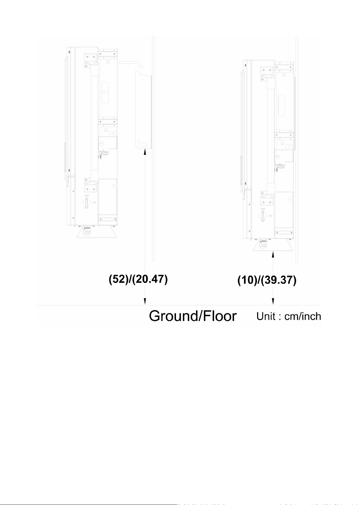
∙ ISMG3 inverters, that must be vertically mounted, can be located indoor or
outdoor according to protection degree of enclosure IP55.
∙ Leave at least 50 cm (19.7 inches) of free space above and 100 cm (39.4
inches) below the inverter when installed outdoor. Allow 20 cm (7.9 inches)
between inverters when installing multiple inverters for better ventilation (see
Fig 2.1.1).
∙ Mount the inverter on a wall that is strong enough to withstand the inverter
with 75 kg weight.
∙ Avoid mounting the inverter on a location directly exposed to sunlight to
maintain the ambient temperature of the inverter within -25° and 60 °C (-13°
and 140°F). Humidity shall be within 0% and 95%.
12

WARNING!
Some parts of the cooling surface can reach temperatures over
70°C (158°F) when the inverter is in operation. Do not operate the
inverter where it exposes to flammables, explosive atmospheres or
close to combustibles or unknown materials that may result in
fire/expolsion danger.
WARNING!
Do not expose the inverter to the corrosive liquids and/or gases.
Keep DC wirings as short as possible to minimize power loss.
The mounting bracket should be fastened on a concrete or a masonry wall
with the recommended anchors.
Fig 2.1.1 Clearances required for ISMG3 inverter installation
13

2.2 Mounting
The steps listed below describe how to mount the inverter on the wall:
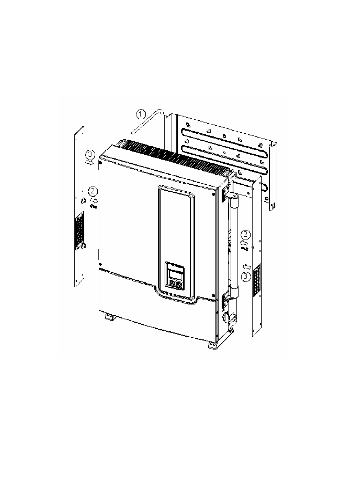
1. After taking out the inverter from the carton, the attached mounting bracket
shall first be removed from the inverter by following the steps shown in Fig
2.2.1 below.
Fig 2.2.1 To remove the mounting bracket from the inverter
14

2. Use the mount bracket (Fig 2.2.2) as a template to mark the location of the
holes to be drilled in the wall. After drilling the holes, the mounting bracket is
then held against the wall and fastened to the wall with anchors as shown in
Fig 2.2.3. (At least ten (10) screws required)
For mounting on wooden wall, the suggested diameter of screw is at least
6.35mm and the length is 25.4mm. The nut size needs to be at least 12.7mm.
A minimum of 10 screws are required to mount the bracket on wooden wall
For mounting on steal plate, the suggested screw size is M8x16. A minimum
of 8 screws are required to mount the bracket on steel plate
For mounting on cement wall, the suggested anchor screw with outer
diameter of 8mmx38.1mm is recommended. The nut size needs to be at least
12.7 mm. A minimum of 8 screws are required to mount the bracket on
cement wall
Fig 2.2.2 Inverter mounting bracket
15

Fig 2.2.3 Fasten the mounting bracket
16
3. Once the mounting bracket is fastened to the wall, the inverter can be
mounted and fastened on the bracket. Hook the inverter on the mounting
bracket flanges and slip down carefully to lock it in place. And then fasten the
inverter to the mounting bracket as shown in Fig 2.2.4.
17
18
 Loading...