

Page 1
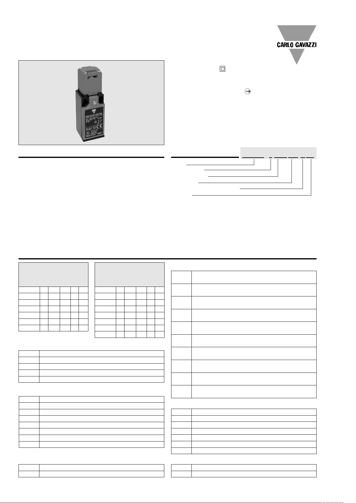
Limit Switches - Safety Type
Plastic Body IP65
and Metal Body IP66
Product Description
They are developed in order to be
used for following operations:
For monitoring and protection of
industrial machines, without
inertia, in which down-timeisless
than access time to the
dangerous area.
Use on slidingor pivoting protectors
(covers, cases, doors, grids,etc.).
To protect operators working on
dangerous machines, by opening
the control circuit. Withdrawal of
key by opening the mobile
protector, causes immediate
stopping of the machine drive.
Specific limit switches ideal for
monitoring and protection of light
industrial machines without
inertia, equipped with angular
movement protectors (doors,
hinges, rotative covers, grid, etc.).
Detection by the rotative axis or
by means of a lever. Opening of
the mobile protector guarantees
operatorprotectionby immediately
stopping the machine drive.
To control the access point of the
hazardous area.
• High mechanical resistant
• Double Insulation (for thermoplastic type)
• Degree of protection IP65 (thermoplastic) IP66 (metal)
Reinforced UL-V0 thermoplastic fiber-glass body
•
• Zinc alloy (Zamack) or aluminium body
• Positive Opening Operation
• Minimum Actuation Force/Torque
• Minimum Force to achieve Positive Opening Operation
• Precise operating points (consistency)
• Immune to electromagnetic disturbances
• Zb type contact blocks
• Current Ith = 10A
Rated insulation voltage Ui = 500V
•
• UL, CSA, CE
• Conform with IEC 947-5-1 (EN 60947-5-1)
Ordering Key
Body
Cable Gland
Contact block
Head type
Material of body and head
Options
PS21S-PS1105-T00
Description of the key codes
for
Key actuator
(key must be ordered separately)
Hinge and Wire
PS21S P S11 05 T 00
PS42S N S02 09 Y
PS21H B T11 HZ
PS42H A O11 HS
M T02 HC
PS21R N6
PS42R N7 K0
4
(key must be ordered separately)
PS31S P S11 05 Y 00
PS43S N S02 T
PS31R O11 N7
PS43R T02 N7 K0
Cable Gland
M20
M
PG13.5
P
PG11
B
M16
A
1/2 NPT
N
Contact block
1NO+1NC overlap slow(+)
O11
2NC snap(+)
S02
1NO+1NC snap(+)
S11
2NC slow(+)
T02
3NC slow(+)
T03
1NO+1NC slow(+)
T11
1NO+2NC slow(+)
T12
2NO+1NC slow(+)
T21
Material of body and head Options
Thermoplastic Body and Thermoplastic head
T
Metal Body and Thermoplastic head
Y
for
Key actuator
and Wire
M T11
T21
T12
T03
Body
PS21H
5
PS42H
PS21R
4
PS31R
PS42R
PS43R
PS21S
PS31S
PS42S
PS43S
Head type
05
09
HC
HS
HZ
N6
N7
00
K0
PS 30mm/1.18” (fix 20/22mm/0.79”/0.87”)
1 cable inlet for hinge (shaft or pin)
PS 50mm/1.97” (fix 40/42mm/1.57”/1.65”)
2 cable inlet for hinge (shaft or pin)
PS 30mm/1.18” (fix 20/22mm/0.79”/0.87”)
1 cable inlet for pull wire
PS 40mm/1.57” (fix 30mm/1.18”)
1 cable inlet for pull wire
PS 50mm/1.97” (fix 40/42mm/1.57”/1.65”)
2 cable inlet for pull wire
PS 60mm/2.36” (fix 40/42mm/1.57”/1.65”)
3 cable inlet for pull wire
PS 30mm/1.18” (fix 20/22mm/0.79”/0.87”)
1 cable inlet for Key actuator
PS 40mm/1.57” (fix 30mm/1.18”)
1 cable inlet for Key actuator
PS 50mm/1.97” (fix 40/42mm/1.57”/1.65”)
2 cable inlet for Key actuator
PS 60mm/2.36” (fix 40/42mm/1.57”/1.65”)
3 cable inlet for Key actuator
90° Adj. key head
Fully turnable key head
Zinc plated steel LEVER
Stainless steel shaft
Zinc plated steel shaft
Pull wire for simple stop
Pull wire for emergency stop
no option
with reset button
1 Specifications are subject to change without notice.Pictures are just an example. For special features and/or customization, please ask to our sales network.101208
Page 2

Technical Data
Millions of operating cycles
0.1
0.2
0.3
0.5
Current (A)
1
2
3
5
1 2 3 5100.2 0.3 0.5
1
2
2
4
4
8
1
30
23
0 -
24
0
400
1 2 3 510
Current (A)
0.1
0.2
0.3
0.5
1
2
3
5
Millions of operating cycles
1
2
2
4
4
8
130
2
3
0
Plastic Body Metal body
Standards
IEC 60947-1, IEC 60947-5-1, EN 60947-1, EN 60947-5-1,
UL508 and CSA C22-2 n°14
Certifications – Approvals UL – CSA
Air temperature near the device
- during operation
- for storage
Climatic withstand
According to IEC 68-2-3 and salty mist according to IEC 68-2-11
-25°C…+70°C/-13°F...158°F
-30°C…+80°C/-22°F...+176°F
Mounting positions All positions are authorized
Shock withstand (according to IEC 68-2-27 and 60068-2-27)
(1/2 sinusoidal shock for 11ms) no change in contact position
Protection against electrical shocks (
Degree of protection (
according to IEC 529 and EN 60529)
ccordingto IEC 536)
a
40g/1.41oz Limit switch for hinge (pin/shaft) or pull wire (rope)
10g/0.35oz Limit switch with key actuator
Class II Class I
IP65 IP66
Electrical Data
Plastic Body Metal body
Rated insulation voltage U
-according to IEC 60947-1 and EN 60947-1 500V (degree of pollution 3)
-according to UL 508, CSA C22-2 n°14
Rated impulse withstand voltage Uimp
(according to IEC 60947-1 and EN 60947-1)
Conventional enclosed thermal current Ithe
(according to IEC 60947-1 and EN 60947-5-1) (θ≤40°C)
Short-circuit protection - gG type fuses
Rated operational current
Ie / AC-15 - acc.to IEC 60947-5-1 24VAC (50/60 Hz)
- acc.to UL 508, CSA C22 n°14
Ie / DC-13 - acc.to IEC 60947-5-1 24VDC
- acc.to UL 508, CSA C22 n°14
Electrical durability (according to IEC 60497-5-1 annex C)
- max. switching frequency Cycles/h
- load factor
Connecting data of contact blocks
Connecting terminals
Connecting capacity 1 or 2 x mm2/ AWG
Terminal marking
Positivity
i
400V (PS21,PS42), 500V (PS31,PS43)
(degree of pollution 3)
A 600 Q600
A 300 Q 300 (PS21, PS42)
A 600 Q 600 (
6kV
10A
10A
10.0A
130VAC (50/60 Hz)
230VAC (50/60 Hz)
240VAC (50/60 Hz)
400VAC (50/60 Hz)
5.5A
3.1A
3.0A
1.8A
Q 600 Q 300 (PS21/42) Q 600 (PS31/43)
2.8A
110VDC
250VDC
0.6A
0.27A
Q 600 Q 300 (PS21/42) Q 600 (PS31/43)
Utilization categories AC-15 and DC-13 (see curves and value below)
3600
0.5
M3.5 (+,-) pozidriv 2 screw with cable clamp
0.5mm2/ AWG 20 to 2.5mm2/ AWG 14
According to EN 50013
Contacts with positive opening operation as per IEC 60947-5-1 chapter 3
PS31, PS43)
Diagram for snap action
contact:
Specifications are subject to change without notice.Pictures are just an example. For special features and/or customization, please ask to our sales network.101208 2
Diagram for slow action
contact:
Electrical durability for DC-13 utilization category
Power breaking for a durability of 5 million operating cycles
Snap action Slow action
Voltage 24V 9.5W 12W
Voltage 48V 6.8W 9W
Voltage 110V 3.6W 6W
Page 3

24.1/0.95”
30/1.18”
37/1.46”
24.1/0.95”
12.5/0.49”
6.6/
0.27”
54.5/2.15” 2/0.08”
40/1.57”
42/1.65”
52/2.05”
59/2.32”
2
0/0.79”
22/0.87”
Ø5.2
0.20”
1
12.5/
0.49”
1
4/0.55”
36/1.42”
Pg13.5 (x3)
1/2" NPT (x3)
Pg11 (x3)
M16x1,5 (x3)
M
20x1,5 (x3)
Limit Switches - Safety Type (PS42S/H/R)
24.1/0.95”
39/1.54”
45.6/1.80”
2
4.1/0.95”
12.5/0.49”
6
.6/
0.27”
24.2/0.95”
17.5/0.69”
26.5/1.04”
20.4/0.80”
51.2/2.01”
2
3.0/0.91”
13.2/0.52”
7.0/0.28”
M4 x 2
73.2x2/
2.88”x2
26.7/1.05”
Ø8.3/
0.32”
Ø12/0.47”
17.5/0.69”
16.0/0.63”
86.5/3.41”
5.3/0.21”
54/2.13”
5/0.20”
2/0.08”
39/1.54”
24/0.94”
Metal Body IP66
Cable Gland
P = one cable inlet PG13.5 cable gland
M = one cable inlet M20x1.5 cable gland
N = one cable inlet 1/2” NPT cable gland
B = one cable inlet PG11 cable gland
A = one cable inlet M16x1.5 cable gland
Contact block (Zb type)
S11 (1NO+1NC)
Snap Action
T02 (2NC)
Slow Action
Conformity / (NC)
Max. Actuation speed
Min. force or torque
Weight
T11 (1NO+1NC)
Non overlapping
Slow action
S02 (2NC)
Snap Action
EN 50047 /
0.5m/s / 1.64ft/s
15N / 30Nm
285.0g / 10.053oz
mm/inches
m/inches
m
O11 (1NO+1NC)
Overlapping
Slow Action
S11 T11 O11
T02 S02
90° adjustable head
Code PS42S- 05-Y00
S11 T11 O11
T02 S02
Conformity / (NC)
Max. Actuation speed
Min. force or torque
Weight
EN 50047 /
0.5m/s / 1.64ft/s
15N / 30Nm
296.0g / 10.441oz
mm/inches
Fully turnable head
Code PS42S- 09-Y00
S11 T11 O11
T02 S02
Conformity / (NC)
Max. Actuation speed
Min. force or torque
Weight
EN 50047 /
Shaft for hinge
0.5m/s / 1.64ft/s Code Zinc plated steel
0.12N / 0.60Nm Stainless steel
297.0g / 10.476oz
PS42H- HZ-Y00
PS42H- HS-Y00
S11 T11 O11
mm/inches
T02 S02
Conformity / (NC)
Max. Actuation speed
Min. force or torque
Weight
11 Specifications are subject to change without notice.Pictures are just an example. For special features and/or customization,please ask to our sales network. 101208
EN 50047 /
0.5m/s / 1.64ft/s
0.12N / 0.60Nm
297.0g / 10.476oz
Zinc plated steel lever
Code PS42H- HC-Y00
Page 4

24/0.94”
4/0.16”6/0.24”
90.75/3.57”
15/0.59”
12.5/
0
.49”
10/
0
.39”
2
4/0.94”
4/0.16”6/0.24”
90.75/3.57”
12.5/
0.49”
10/
0.39”
S11 T11 O11
mm/inches
T02 S02
Conformity / (NC)
Max. Actuation speed
Max wire lenght
eight
W
6m/19.68ft ÷ 15m/49.21ft
292.0g / 10.300oz
/
Pull wire without reset for simple stop
Code PS42R- N6-Y00
S11 T11 O11
mm/inches
T02 S02
Conformity / (NC)
Max. Actuation speed
Max wire lenght
Weight
EN 50047 /
6m/19.68ft ÷ 15m/49.21ft
297.0g / 10.476oz
Pull wire with reset for emergency stop
Code PS42R- N7-YK0
Operating Key
K13 K14 K15 K16 K17 K18 K19
Bent Key
22mm/0.87”
Flat Key
22mm/0.87”
Bent Key
13mm/0.51”
Flat Key
13mm/0.51”
Shock absorbing
bent key
Shock absorbing
flat key
Adjustable joint
key
Accessories for Pull Wire Limit Switches
Specifications are subject to change without notice. Pictures are just an example.For special features and/or customization, please ask to our sales network. 080910 12
OCC 8 MOR 05 RED 05 FUN 05
Stay bolt Rope Clamp Rope Eye
Rope 5mm x 100m
0.20” x 328.08ft
Page 5

Utilization precautions
Maximum lenght application of pullwire head
PS21, PS42: 6m/19.70ft max.
PS31, PS43: 16m/52.49ft max.
Example of applications
5m
≤
16.40ft
≤
≤
16.40ft
≤
PS21, PS42: 15m/49.21ft max.
PS31, PS43: 25m/82.02ft max.
5m
≤
16.40ft
≤
5m
≤
16.40ft
≤
5m
≤
16.40ft
≤
5m
Key actuator type Head for hinge (by pin) Head for hinge (by shaft)
Adjustment
Accessories for Pull Wire Limit Switches
5 way key actuator head
OCC 8
Stay bolt
MOR 05
Rope Clamp
RED 05
Rope Eye
FUN 05
Rope 5mmx100m
0.20” x 328.08ft
15 Specifications are subject to change without notice. Pictures are just an example.For special features and/or customization, please ask to our sales network. 080910
 Loading...