

Page 1
ICS, IP69K, M12
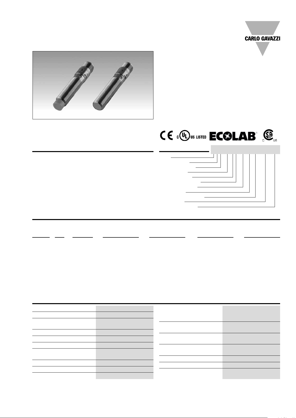
Proximity Inductive Sensors - Ecolab certified
Standard and Extended Range, Stainless Steel Housing
Types ICS, IP69K, M12
• Sensing distance: 2 to 8 mm
• Flush or non-flush mountable
• Long body version
• Rated operational voltage (U
• Output: DC 200 mA, NPN or PNP
• Normally open or normally closed
• 4 x 90° LED indication for output ON, short-circuit and
overload
• Protection: reverse polarity, short circuit, transients
• M12 plug version
• According to IEC 60947-5-2
• High-pressure washdown resistant
• Ecolab certified, FDA-certified plastic
• Laser engraved on the housing, permanently legible
• Extended temperature range: -40°C...+80°C
• CSA certified for Hazardous Locations
): 10 - 36 VDC
b
Product Description Ordering Key
A family of inductive proximity switches in stainless steel
(AISI 316L) ideal for food
and beverage applications
where sensors are exposed
to high pressure and high
temperature cleaning processes.
They are fully sealed and
resistant to all common
acid and alkaline cleaning
agents and disinfectants
(Ecolab certified). IP68 and
IP69K-rated products. Output is open collector NPN or
PNP transistors.
Type
Housing style
Housing material
Housing size
Housing length
Detection principle
Sensing distance
Output type
ICS12LF04NOM1-FB
Output configuration
Connection
Washdown series
Type Selection
Connec- Body Rated Ordering no. Ordering no. Ordering no. Ordering no.
tion style operating NPN, PNP, NPN, PNP,
distance S
Standard range
Plug Long 2 mm
Plug Long 4 mm
Extended range
Plug Long 4 mm
Plug Long 8 mm
1)
For flush mounting in metal
Normally open Normally open Normally closed Normally closed
n
1)
ICS12LF02NOM1-FB ICS12LF02POM1-FB ICS12LF02NCM1-FB ICS12LF02PCM1-FB
2)
ICS12LN04NOM1-FB ICS12LN04POM1-FB ICS12LN04NCM1-FB ICS12LN04PCM1-FB
1)
ICS12LF04NOM1-FB ICS12LF04POM1-FB ICS12LF04NCM1-FB ICS12LF04PCM1-FB
2)
ICS12LN08NOM1-FB ICS12LN08POM1-FB ICS12LN08NCM1-FB ICS12LN08PCM1-FB
2)
For non-flush mounting in metal
Specifications
Rated operational voltage (Ub)
Ripple ≤ 10%
Output current (I
) ≤ 200 mA @ 50°C
e
(≤ 150 mA @ 50-80°C)
OFF-state current (I
) ≤ 10 μA
r
No load supply current (I
Voltage drop (U
) Max. 2 VDC @ 200 mA
d
Protection Reverse polarity,
short-circuit, transients
Voltage transient 1 kV/0.5 J
Power ON delay (t
) ≤ 20 ms
v
Operating frequency (f) ≤ 2000 Hz
Specifications are subject to change without notice (08.01.16) 1
10 to 36 VDC (ripple incl.)
) ≤ 15 mA
o
Indication for output ON
Activated LED, yellow (4x90°)
NO version Target present
NC version Target not present
Indication for short circuit/
overload LED blinking (f = 2 Hz)
Assured operating
sensing distance (S
) 0 ≤ Sa ≤ 0.81 x S
a
n
Effective operating
distance (S
Usable operating distance (Su)
) 0.9 x Sn ≤ Sr ≤ 1.1 x S
r
0.9 x Sr ≤ Su ≤ 1.1 x S
n
r
Repeat accuracy (R) ≤ 5%
Differential travel (H)
(Hysteresis) 1 to 20% of sensing dist.
Page 2
ICS, IP69K, M12
Specifications (cont.)
Ambient temperature
Operating
-40° to +80°C (-40° to +176°F)
short exposure (15’) to
100°C during cleaning
process
Storage
-40° to +80°C (-40° to +176°F)
Shock and vibration IEC 60947-5-2/7.4
Housing material
Body Stainless steel (AISI 316L)
Front
Grey PPS - FDA-certified
Connection
Plug M12 x 1
Degree of protection IP67, IP68 (1 m, 7 days),
IP69K
Weight (cable/nuts included) Max. 35 g
Dimensions See diagrams below
Tightening torque 25 Nm
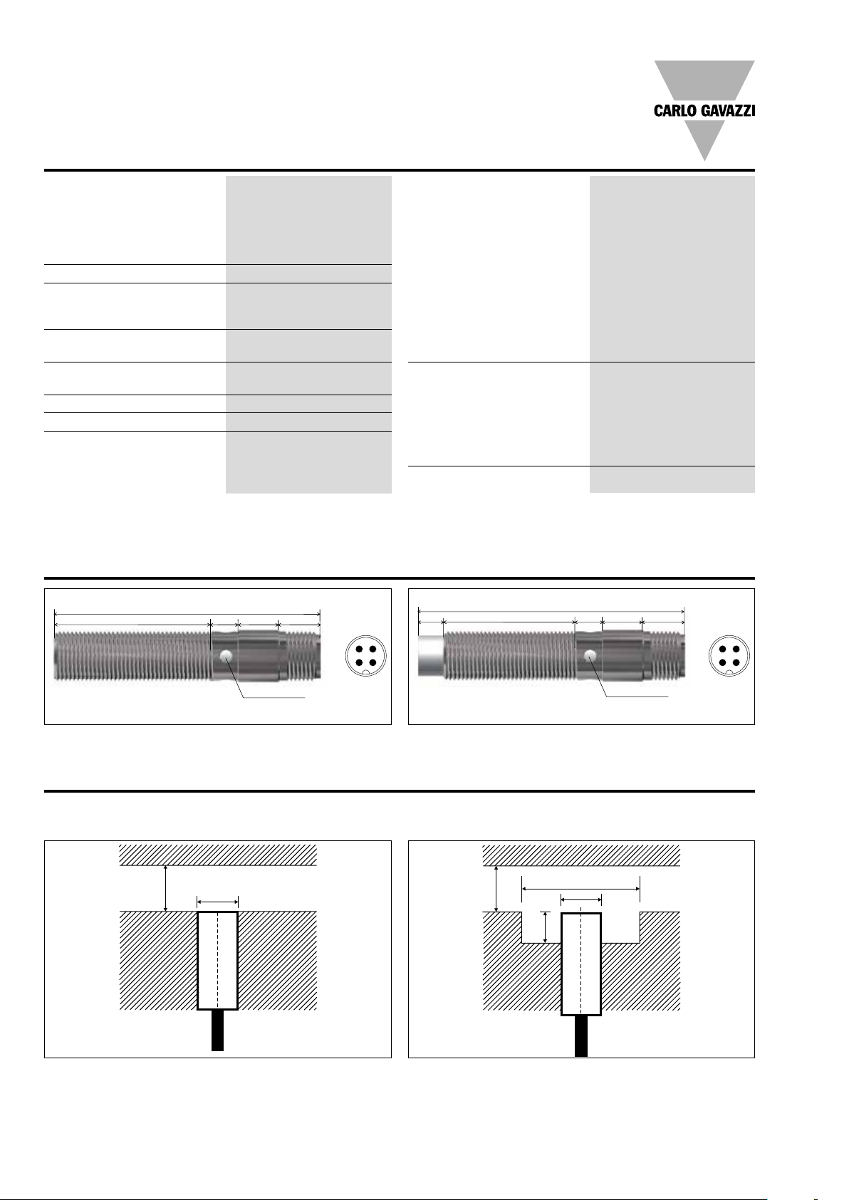
Dimensions (mm)
Approvals cULus (UL508)
cCSAus As Process Control
Equipment for Hazardous
Note: The terminal connector
(version ...M1) was not
evaluated. The suitability of
the terminal connector should
be determined in the end-use
application.
Locations.
- Class I, Division 2,
Groups A, B, C and D.
- T5, Enclosure Type 4.
Ambient temperature
Ta: -25° to +60°C
CCC is not required for
products with a maximum
operating voltage of ≤ 36 V
EMC protection According to IEC 60947-5-2
IEC 61000-4-2 (ESD) 8 KV air discharge,
4 KV contact discharge
IEC 61000-4-3 3 V/m
IEC 61000-4-4 2 kV
IEC 61000-4-6 3 V
IEC 61000-4-8 30 A/m
MTTF
770 years @ 50°C (122°F)
d
Flush version
38.7 6.2 9.6 10.3
64.8
LED (4 x 90°)
3
142
6.2
Non-flush version
Installation
Flush mountable proximity switches, when installed in
damping material, must be according to Picture 1A.
Picture 1A Picture 1B
≥ 3 x S
n
d
Free zone or
non-damping
material
Non-flush mountable proximity switches, when installed in
damping material, must be according to Picture 1B.
≥ 3 x S
64.8
32.5 6.2 9.6 10.3
n
≥ 3 x d
d
**
3
142
LED (4 x 90°)
Free zone or
non-damping
material
: nominal sensing distance
S
n
d : sensor diameter (12 mm)
: nominal sensing distance
S
n
d : sensor diameter (12 mm)
** ≥ 6 mm, Sn = 4 mm (1x)
≥ 12 mm, Sn = 8 mm (2x)
2 Specifications are subject to change without notice (08.01.16)
Page 3

ICS, IP69K, M12
Installation (cont.)
Flush mountable proximity switches, when installed together
in damping material, must be according to Picture 2A.
Non-flush mountable proximity switches, when installed
together in damping material, must be according to Picture
2B.
Picture 2A
d d d
d : sensor diameter (12 mm)
Picture 2B
d : sensor diameter (12 mm)
2 x dd
d
dd
For sensors installed opposite each other, a minimum space of 6 x Sn (the nominal sensing distance) must be observed (See
Picture 3).
Picture 3
≥ 6 x S
n
Wiring Diagram
1 BN
4 BK
3 BU
NPN - Normally open
+
-
Sn : nominal sensing distance
1 BN
2 BK
3 BU
NPN - Normally closed
+
-
1 BN
4 BK
3 BU
PNP - Normally open
+
-
PNP - Normally closed
1 BN
2 BK
3 BU
+
-
Specifications are subject to change without notice (08.01.16) 3
Page 4

ICS, IP69K, M12
Reduction Factors
The rated operating distance
is reduced by the use of
metals and alloys other than
Fe360.
Picture 4
Fe360 : Steel
CrNi : Chrome-nickel
CuZn : Brass
Al : Aluminium
Cu : Copper
Sr : Effective operating distance
Delivery Contents
• Inductive proximity switch ICS.
• 2 nuts stainless steel
• Packaging: plastic bag
The most important reduction factors for inductive
proximity sensors are shown
in Picture 4.
IP69K Connector Cables
4-wire angled connector,
2 m cable CONB14NF-AP2W
4-wire angled connector,
5 m cable CONB14NF-AP5W
4-wire straight connector,
2 m cable CONB14NF-SP2W
4-wire straight connector,
5 m cable CONB14NF-SP5W
For any additional information
or different options,
please refer to the
“General Accessories”
datasheets.
4 Specifications are subject to change without notice (08.01.16)
 Loading...