

Proximity Sensors Inductive
Extended Range, Nickel Plated Brass Housing
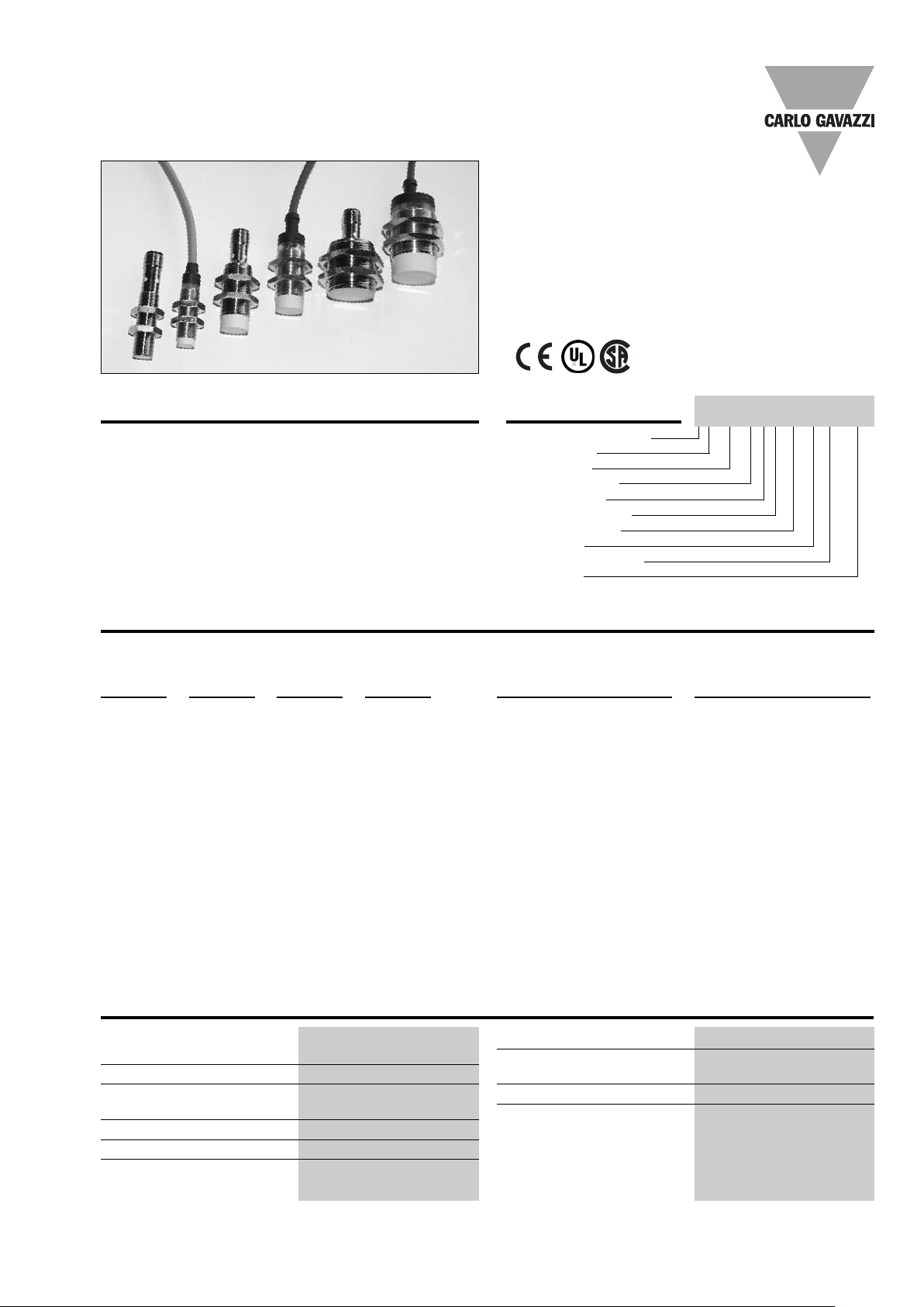
Types IA, DC, M12, M18 and M30, 2-wire
• Sensing distance: 4 to 22 mm
• Flush and non-flush types
• Power supply: 10 to 40 VDC
• Output: Transistor
• Make or break switching
• Protection: Reverse polarity, short-circuit and transients
• 2 m cable or plug M12
Diameter: M12, M18, M30
•
Product Description
Proximity switch M12, M18
and M30 in nickel-plated
brass housings. Made in
accordance with Euronorm
EN 60 947-5-2.
Ordering Key
Cap. proximity switch
Housing style
Housing size
IA12ASF04DOM1
Housing material
Housing length
Detection principle
Sensing distance
Output type
Output configuration
Connection
Type Selection
Housing Body Connec- Rated Ordering no. Ordering no.
diameter style tion operating 2 wire DC 2 wire DC
dist. (S
M12 Short Cable 4 mm
M12 Short Plug 4 mm
M12 Short Cable 8 mm
M12 Short Plug 8 mm
M18 Short Cable 8 mm
M18 Short Plug 8 mm
M18 Short Cable 14 mm
M18 Short Plug 14 mm
) Normally open Normally closed
n
1)
1)
)
2
2)
1)
1)
2)
2)
IA 12 DSF 04 DO IA 12 DSF 04 DC
IA 12 ASF 04 DO M1 IA 12 ASF 04 DC M1
IA 12 DSN 08 DO IA 12 DSN 08 DC
IA 12 ASN 08 DO M1 IA 12 ASN 08 DC M1
IA 18 DSF 08 DO IA 18 DSF 08 DC
IA 18 ASF 08 DO M1 IA 18 ASF 08 DC M1
IA 18 DSN 14 DO IA 18 DSN 14 DC
IA 18 ASN 14 DO M1 IA 18 ASN 14 DC M1
M30 Short Cable 15 mm
M30 Short Plug 15 mm
M30 Shor
M30
1)
For flush mounting in metal
2)
For non-flush mounting in metal
t
Short
Cable 22 mm
Plug
22 mm
1)
1)
2)
2)
IA 30 DSF 15 DO IA 30 DSF 15 DC
IA 30 ASF 15 DO M1 IA 30 ASF 15 DC M1
IA 30 DSN 22 DO IA 30 DSN 22 DC
IA 30 ASN 22 DO M1
IA 30 ASN 22 DC M1
Specifications
Rated operational volt. (Ue) 12 to 36 VDC
(UB)
10 to 40 VDC (ripple included)
Ripple ≤ 10%
Rated operational current (Ie)
Continuous ≤ 5-100 mA
No-load supply current (I) ≤ 0.8 mA
Voltage drop (Ud) ≤ 3 VDC at max. load
Protection Reverse polarity
,
short-circuit, transients
Specifications are subject to change without notice (06.06.05) 1
Transient voltage ≤ 1 kV/0.5 J
EMC Appr
oved according to
EN 50 080, EN 50 081
Power ON delay < 50 ms
Frequency of operating IA12xSF 1000 Hz
cycles (f) IA12xSN 800 Hz
IA18xSF 500 Hz
IA18xSN 400 Hz
IA30xSF 400 Hz
IA30xSN 200 Hz

C
D
E
F
SW
A
LED
B
C
D
F
SW
A
LEDs
M12 x 1 x 9.5
B
IA, DC, M12, M18 and M30, 2-wire
Specifications (cont.)
Indication LED, yellow
Repeat accuracy (R) ≤ 10%
Hysteresis (H) (Differential travel)
Assured operating dist. (Sa)0 ≤ Sa≤ 0.77 S
Effective operating dist. (Sr) 0.9 x Sn≤ Sr≤ 1.1 x S
1 to 20% of sensing distance
n
n
Usable operating dist. (S) 0.85 x Sr≤ Su≤ 1.15 x S
Connection
Cable 2 m, 2 x 0.5 mm2,
Plug M12 x 1
Cables for plug (-1)
Weight (cable excluded) IA 12xxx 20 g
r
Ambient temperature
Operating
Storage
Degree of protection IP 67 (Nema 1, 3, 4, 6, 13)
-25° to +70°C (-13° to +158°F)
-30° to +80°C (-22° to +176°F)
Tightening torque IA 12 (x) 7 Nm
Housing material
Body In nickel-plated brass
ont Grey thermoplastic polyester
Fr
Back
Black polyester (cable)
In nickel-plated brass (plug)
Approvals CSA, UL
CE-marking Ye s
Dimensions
Type A B C D E F SW
IA 12 DSF 04 D.
M 12 x 1 x 38 10.7 38 11 5.0 4 17
IA 12 ASF 04 D. M1 M 12 x 1 x 38 10.7 38 25.2 4 17
IA 12 DSN 08 D. M 12 x 1 x 38 10.7 42 11 5.0 4 17
IA 12 ASN 08 D. M1 M 12 x 1 x 38 10.7 42 25.2 4 17
IA 18 DSF 08 D. M 18 x 1 x 30 16.7 30 11.6 15.4 424
IA 18 ASF 08 D. M1 M 18 x 1 x 30 16.7 30 25.0 4 24
IA 18 DSN 14 D. M 18 x 1 x 30 16.7 38 11.6 15.4 4 24
IA 18 ASN 14 D. M1 M 18 x 1 x 30 16.7 38 25.0 4 24
IA 30 DSF 15 D. M 30 x 1.5 x 30 28 30 13.6 15.4 5 36
IA 30 ASF 15 D. M1 M 30 x 1.5 x 30 28 30 25.0 5 36
IA 30 DSN 22 D. M 30 x 1.5 x 30 28 42 13.6 15.4 5 36
IA 30 ASN 22 D. M1 M 30 x 1.5 x 30 28 42 25.0 5 36
Ø mm mm mm mm mm mm
grey PVC, oil proof
CONH1A serie
IA 18xxF 26 g
IA 18xxN 30 g
IA 30xxF 50 g
A 30xxN
I
0 g
8
15 Nm
IA 18 27.5 Nm
IA 30 50 Nm
Cable type
Plug type
Wiring Diagrams
“PNP”
1
BN+
DC 2-wire
make switching (NO)
LOAD
4
1
BU-
BN+
DC 2-wire
break switching (NC)
LOAD
2
2 Specifications are subject to change without notice (06.06.05)
BU-
“NPN”
DC 2-wire
make switching (NO)
DC 2-wire
break switching (NC)
1
4
1
2
LOAD
LOAD
BN+
BU-
BN+
BU-

A, DC, M12, M18 and M30, 2-wire
I
Power Supplies
Power supplies VDC: > SS 130/140.
Installation Hints
current peaks, separate the prox. switch power cables from any other power cables, e.g.
motor, contactor or solenoid cables
Relief of cable strain
Incorrect
Correct
The cable should not be pulled
Protection of the sensing face Switch mounted on mobile carrierTo avoid interference from inductive voltage/
A proximity switch should not serve as
mechanical stop
Any repetitive flexing of the
cable should be avoided
Specifications are subject to change without notice (06.06.05) 3
 Loading...