

Page 1

EN ITDA ES FR DE
EM24 E1
USER MANUAL
MANUALE UTENTE
BETRIEBSANLEITUNG
MANUEL D’EMPLOI
INSTRUCCIONES DE USO
BRUGERMANUAL
Page 2

EM24 E1
Three-phase energy analyzer
USER MANUAL
Page 3

Contents
EM24 E1 4
Introduction 4
Description 4
UCS (Universal Conguration Software) 4
EM24 E1 use 5
Introduction 5
Display 5
Network parameters setting 6
Setting network parameters via DHCP 6
Setting network parameters without DHCP 6
Working with EM24 E1 7
Working with the measurement/info menu 7
Working with the settings menu 7
Resetting partial energy meter 7
Setting a parameter 8
Menu description 9
Measurement menu - measurement pages 9
Information Menu 10
Settings from EM24 E1 11
General settings 11
Essential information 12
Applications 12
Programming pages 13
Managing taris via Modbus command 14
Disabling tari management 14
Frontal LED 14
Frontal selector 14
Maintenance and disposal 15
3EM24 E1 - Instruction manual | CARLO GAVAZZI Controls SpA
Page 4

Information property
Copyright © 2018, CARLO GAVAZZI Controls SpA
All rights reserved in all countries.
CARLO GAVAZZI Controls SpA reserves the right to apply modifications or make improvements to the relative documentation
without the obligation of advance notice.
Safety messages
The following section describes the warnings related to user and device safety included in this document:
NOTICE: indicates obligations that if not observed may lead to damage to the device.
CAUTION! Indicates a risky situation which, if not avoided, may cause data loss.
IMPORTANT: provides essential information on completing the task that should not be neglected.
General warnings
This manual is an integral part of the product and accompanies it for its entire working life. It should be consulted for all
situations tied to configuration, use and maintenance. For this reason, it should always be accessible to operators.
NOTICE: no one is authorized to open the analyzer. This operation is reserved exclusively for CARLO GAVAZZI technical
service personnel.
Protection may be impaired if the instrument is used in a manner not specified by the manufacturer.
Service and warranty
In the event of malfunction, fault, requests for information, contact the CARLO GAVAZZI branch or distributor in your country.
Installation and use of analyzers other than those indicated in the provided instructions void the warranty.
Download
This manual www.productselection.net/MANUALS/UK/EM24_im_use.pdf
Installation instruction - EM24 www.productselection.net/MANUALS/UK/EM24_im_inst.pdf
UCS software www.productselection.net/Download/UK/ucs.zip
4 EM24 E1 - Instruction manual | CARLO GAVAZZI Controls SpA
Page 5

EM24 E1
Introduction
EM24 is a three-phase energy analyzer for DIN-rail mounting, with configuration joystick, frontal selector and LCD display.
The direct connection version (AV2) allows to measure up to 65 A, the CT connection version (AV5) allows to measure up to 34875 A by
means of current transformers (5 A secondary output).
The DHCP function is able to speed the commissioning and all the configuration parameters can be set up via UCS.
Description
AV2 AV5
Part
Description
A LCD display
B Voltage/current connections
C Joystick
D Selector with pin for MID seal (programming block)
E Inputs/outputs or communication port
F Pins for MID seal (protection covers included)
UCS (Universal Conguration Software)
UCS desktop is available for free download. It can be connected to EM24 via Ethernet (Modbus TCP/IP) .
The following is possible with UCS:
• configure EM24 (online or offline)
• view system status for diagnostics and configuration checks function overview
5EM24 E1 - Instruction manual | CARLO GAVAZZI Controls SpAEM24 E1 - Instruction manual | CARLO GAVAZZI Controls SpA
Page 6

EM24 E1 use
Introduction
EM24 is organized in two menus:
• measurement and information menu: pages used to display the measurement pages, information relevant to the programmed parameters
and instrument firmware release
• settings menu: pages used to set parameters
Display
The display is divided into 3 lines.
Symbol Description
Displaying of phase-to-neutral system voltage
Displaying of phase-to-phase system voltage
Displaying of max values
User ID
EEEE
Displaying of system variables
Displaying of dmd variables
Overflow.
Note: the DMD calculation, the hour-counter and the
energy meters functions are inhibited and the alarm
outputs are activated. The indication “EEEE” in a single
phase variable automatically implies the overflow condition of the relevant system variable, and the PF indication is forced to “0.000”.
6 EM24 E1 - Instruction manual | CARLO GAVAZZI Controls SpA
Page 7

Network parameters setting
Setting network parameters via DHCP
Step Action
1 Install EM24
2 Enable DHCP and exit with End
3 Connect the EM24 to the LAN network to which the PC is connected
4 Access the Info pages to view the assigned network parameters
5 Start UCS software and connect to EM24 via Manual connection> Modbus TCP
6 Enter the IP address displayed on the Info page (see point 4)
7 Access the settings, disable DHCP and assign the required network parameters (assigned by network administrator)
Setting network parameters without DHCP
Step Action
1 Install EM24
2 Disable DHCP (default setting)
3 Connect the PC to the EM24 via Ethernet cable (point to point connection)
Set the PC network properties as follows:
• static IP address
4
5
6 Access the settings and enter the required network parameters
7 Disconnect the Ethernet cable and connect the EM24 to the network to which the Modbus master is connected
• IP address of the same class as the EM24, e.g. if the IP of EM24 is 192.168.1.10 (default), you can set the PC address to
192.168.1.20
• Subnet mask: 255.255.255.0
• Gateway: not necessary
Start UCS software and connect to EM24 via Manual connection> Modbus TCP, enter the EM24 IP address
(192.168.1.10 by default)
7EM24 E1 - Instruction manual | CARLO GAVAZZI Controls SpAEM24 E1 - Instruction manual | CARLO GAVAZZI Controls SpA
Page 8
EM24 E1 use
Working with EM24 E1
Working with the measurement/info menu
to previous info page to next info page
to previous measurement page
to next measurement page
to sengs menu
Working with the settings menu
increase a parameter value
edit/conrm
to previous page to next page
decrease a parameter value
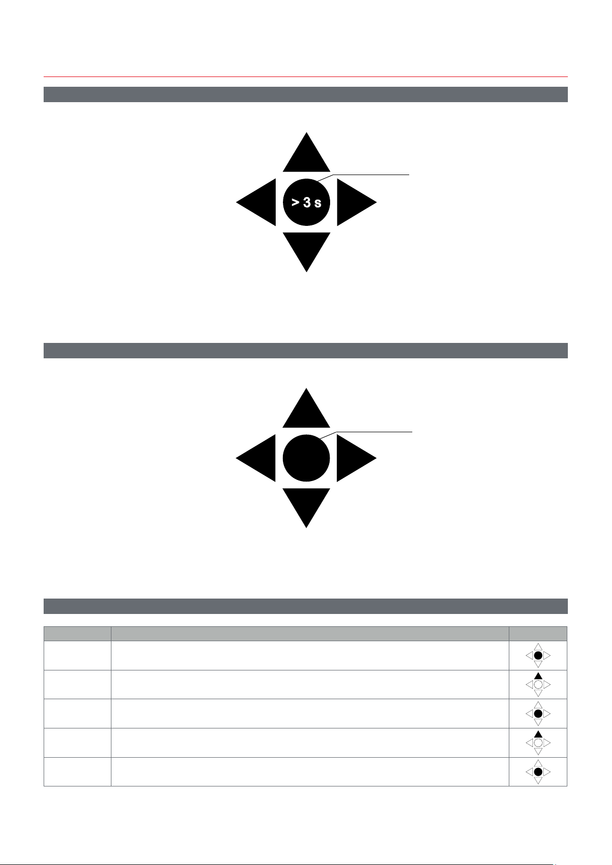
Resetting partial energy meter
Step Action Button
1 Press the button for at least 3 seconds
2 In the PASS page, set the password 1357
3 Confirm operation
4 In the rESEt page, set YES
5 Confirm operation
8
EM24 E1 - Instruction manual | CARLO GAVAZZI Controls SpA
Page 9
EM24 E1 use
Step Action Button
6 In the EnE PrES page, set YES
7 Confirm operation
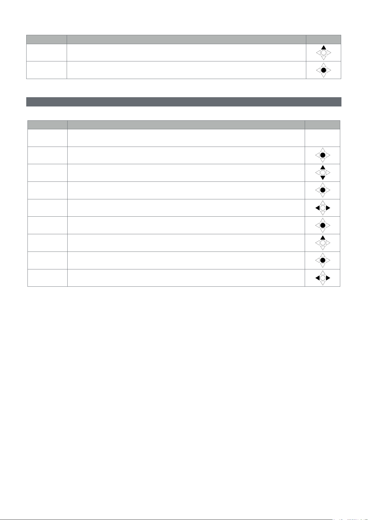
Setting a parameter
Example procedure: how to set Ct rAtio=20 and save changes.
Step Action Button
1 Power on the energy analyzer
2 Press the joystick for at least 3 seconds
3 In the PASS? page, select the correct password (default 0)
4 Confirm operation
5 Scroll pages until Ct rAtio
6 Enter the editing mode
7 Select 20
8 Confirm operation
9 Scroll pages until End to exit
EM24 E1 - Instruction manual | CARLO GAVAZZI Controls SpAEM24 E1 - Instruction manual | CARLO GAVAZZI Controls SpA
9
Page 10

EM24 E1 use
Menu description
Measurement menu - measurement pages
The displayed pages depend on the application set.
Page Displayed measurements Description
1
V
Hz
LNΣ
L1-L2-L3
L1-L2-L3
2
V
Hz
LLΣ
Tot kWh (+)
3
W
dmd
Σ
WΣ dmd max
kWh
4
A dmd max
PArt
Tot kvarh (+)
5
VAΣ dmd
VAΣ dmd max
kvarh
6
VA
PArt
Σ
kWh (+)
7
t1
W
dmd
Σ
kWh (+)
8
t2
W
dmd
Σ
kWh (+)
9
t3
W
dmd
Σ
kWh (+)
10
t4
W
dmd
Σ
kvarh (+)
11
t1
W
dmd
Σ
kvarh (+)
12
t2
W
dmd
Σ
kvarh (+)
13
t3
W
dmd
Σ
kvarh (+)
14
t4
W
dmd
Σ
kWh (+) X
15
W X
User X
kWh (+) Y
16
W Y
User Y
kWh (+) Z
17
W Z
User Z
Total kvarh (-)
18
VA
dmd
Σ
VAΣ dmd max
Total kWh (-)
19
W
dmd
Σ
WΣ dmd max
Phase sequence
System phase-neutral voltage
Frequency
Phase sequence
System phase-phase voltage
Frequency
Total imported active energy
System active power dmd
System active power dmd max
Active energy
Maximum dmd current
Partial active energy
Total imported reactive energy
System apparent power dmd
System apparent power dmd max
Reactive energy
System apparent power
Partial reactive energy
Imported active energy, tariff 1
System active power dmd
Imported active energy, tariff 2
System active power dmd
Imported active energy, tariff 3
System active power dmd
Imported active energy, tariff 4
System active power dmd
Imported reactive energy, tariff 1
dmd
W
Σ
Imported reactive energy, tariff 2
WΣ dmd
Imported reactive energy, tariff 3
WΣ dmd
Imported reactive energy, tariff 4
WΣ dmd
Imported active energy
Active power
User
Imported active energy
Active power
User
Imported active energy
Active power
User
Total exported reactive energy
System apparent power dmd
System apparent power dmd max
Total exported active energy
System active power dmd
System active power dmd max
10
EM24 E1 - Instruction manual | CARLO GAVAZZI Controls SpA
Page 11

Congure the system
20
21
22
23
24
25
26
27
28
Hours
W
Σ
PF
Σ
Hours
VAr
Σ
PF
Σ
var L1
var L2
var L3
VA L1
VA L2
VA L3
PF L1
PF L2
PF L3
W L1
W L2
W L3
A L1
A L2
A L3
V L1-2
V L2-3
V L3-1
V L1
V L2
V L3
Total load operating hours
System active power
System power factor
Total load operating hours
System reactive power
System power factor
Phase 1 reactive power
Phase 2 reactive power
Phase 3 reactive power
Phase 1 apparent power
Phase 2 apparent power
Phase 3 apparent power
Phase 1 power factor
Phase 2 power factor
Phase 3 power factor
Phase 1 active power
Phase 2 active power
Phase 3 active power
Phase 1 current
Phase 2 current
Phase 3 current
Phase 1-phase 2 voltage
Phase 2-phase 3 voltage
Phase 3-phase 1 voltage
Phase 1 voltage
Phase 2 voltage
Phase 3 voltage
Note: in programming mode, the last displayed page is stored.
Information Menu
Page Page title Information displayed
1 IP o.o.-.- IP address (first part)
2 IP -.-.o.o IP address (second part)
3 Sub o.o.-.- Subnet mask (first part)
4 Sub -.-.o.o Subnet mask (second part)
5 Gateo.o.-.- Default gateway (first part)
6 Gate-.-.o.o Default gateway (second part)
7 Port Modbus TCP port
8 DHCP DHCP enabling
9 Info Ethernet diagnostic
10 Ut ratio VT/PT ratio
11 CT ratio CT ratio
12
(2-3-4-wire)
dmd (time)
13 Pulse LED pulse weight (Number of kWh/kvarh per pulse)
14 Year
1P/2P/3P/3Pn
System
Connection (2-3-4-wire)
Dmd integration time (min.)
Firmware release
Year of production
EM24 E1 - Instruction manual | CARLO GAVAZZI Controls SpAEM24 E1 - Instruction manual | CARLO GAVAZZI Controls SpA
11
Page 12

Congure the system
Settings from EM24 E1
General settings
The available settings depend on the application set.
Page title Sub-menu Description Values Default value
Cng PASS - Change password From 0 to 9999 0
APPLiCAt Application tYP.A
User USEr 1 User From 0 to 9999 1
USEr 2 From 0 to 9999 2
USEr 3 From 0 to 9999 3
dHCP - DHCP enabling oFF/on oFF
IP Addr IP o.-.-.- IP address From 000 to 255 192
IP -.o.-.- From 000 to 255 168
IP -.-.o.- From 000 to 255 1
IP -.-.-.o From 000 to 255 10
SUb SUb o.-.-.- Subnet mask From 000 to 255 255
SUb -.o.-.- From 000 to 255 255
SUb -.-.o.- From 000 to 255 255
SUb -.-.-.o From 000 to 255 0
GAtE GAtE o.-.-.- Default gateway From 000 to 255 192
GAtE -.o.-.- From 000 to 255 168
GAtE -.-.o.- From 000 to 255 1
GAtE -.-.-.o From 000 to 255 1
Port - MODBUS TCP port 502
SELECtor SELEC. 1 Page displayed according to selector
SELEC. 2 From 1 to 28 25
SELEC. 3 From 1 to 28 28
SELEC.LoC From 1 to 28 3
SYS - System 3P.n
Ut rAtio - Voltage transformer ratio (VT) AV5: from 1 to 6975
Ct rAtio - Current transformer ratio (CT) AV5: from 1 to 6975
P int.ti - Dmd integration time (min) From 1 to 30 15
FiLtEr.S - Interval of lter intervention with respect
FiLtEr.Co - Filter coefcient From 1 to 32 2
End - Exit and save - -
position among the available pages for
each application (see”Frontal selector”
on page 15)
to full scale (%)
tYP.b
tYP.C
tYP.d
tYP.E
tYP.F
tYP.G
tYP.H
From 1 to 28 1
3P.1
2P
1P
3P
Note: MID (PFA, PFB): only 3P.n
AV2: N/A
AV2: N/A
From 0 to 100 2
tYP.H
3P.n
1
1
Note: the Ut rAtio is available for compatibility with other versions, even though the AV5 version is not meant to be used with voltage transformers. It should
be therefore set to 1.
12
EM24 E1 - Instruction manual | CARLO GAVAZZI Controls SpA
Page 13

Essential information
Essential information
Measurement management
Applications
Note: if an application with easy connection is selected, for the calculation of the active energy the power is always integrated, both in the case of imported
and exported power . The current direction does not affect the measurement. If an application without easy connection is selected, both the active imported
and exported are available.
Application Measurements Easy connection
System:
• phase sequence
A
B
C
D
E
F
• phase-neutral voltage
• frequency
• total imported active energy
• active power dmd and dmd max
System:
• phase sequence
• phase-neutral voltage
• frequency
• total imported active energy
• active power dmd and dmd max
• total imported reactive energy
• apparent power dmd and dmd max
System:
• phase sequence
• phase-neutral voltage
• frequency
• total imported active energy
• active power dmd and dmd max
• imported active and reactive energy by tariff
Single phase:
• imported active energy
• voltage
System:
• phase sequence
• phase-neutral voltage
• frequency
• total imported and exported active energy
• active power dmd and dmd max
• run hour meter
• active power
• power factor
System:
• phase sequence
• phase-neutral voltage
• frequency
• total imported and exported active energy
• active power dmd and dmd max
• phase-phase voltage
• active energy
• maximum dmd current
• partial active energy
• total imported and exported reactive energy
• apparent power, dmd and dmd max
• partial reactive energy
• run hour meter
• active power
• power factor
YES
YES
YES
YES
NO
NO
EM24 E1 - Instruction manual | CARLO GAVAZZI Controls SpAEM24 E1 - Instruction manual | CARLO GAVAZZI Controls SpA
13
Page 14

Essential information
System:
• phase sequence
• phase-neutral voltage
• frequency
• total imported active energy
• active power dmd and dmd max
• phase-phase voltage
• active energy
• maximum dmd current
• partial active energy
• total imported reactive energy
• apparent power, dmd and dmd max
• reactive energy
G
• run hour meter
• active power
• active power dmd
• reactive power
• power factor
• imported active and reactive energy by tariff
Single phase:
• reactive power per phase
• apparent power per phase
• power factor per phase
• active power per phase
• current per phase
• line-line voltages
• line-neutral voltages
System:
• phase sequence
• phase-neutral voltage
• frequency
• total imported and exported active energy
• active power dmd and dmd max
• phase-phase voltage
• active energy
• maximum dmd current
• partial active energy
• total imported and exported reactive energy
• apparent power, dmd and dmd max
• reactive energy
H
• run hour meter
• active power
• active power dmd
• reactive power
• power factor
• imported active and reactive energy by tariff
Single phase:
• reactive power per phase
• apparent power per phase
• power factor per phase
• active power per phase
• current per phase
• line-line voltages
• line-neutral voltages
YES
NO
Programming pages
The following table shows which programming pages are available for each application
Page Application
A B C D E F G H
Change password x x x x x x x x
Application x x x x x x x x
User - - - x - - - -
DHCP enabling x x x x x x x x
IP address x x x x x x x x
Subnet mask x x x x x x x x
Default gateway x x x x x x x x
MODBUS TCP port x x x x x x x x
14
EM24 E1 - Instruction manual | CARLO GAVAZZI Controls SpA
Page 15
Essential information
Selector x x x x x x x x
System x x x x x x x
VT ratio x x x x x x x x
CT ratio x x x x x x x x
Average power integration time x x x - x x x x
Filter S - - - - - x x x
Filter Co - - - - - x x x
End x x x x x x x x
Tariff management
Managing taris via Modbus command
Change the tariff by entering the value corresponding to the current tariff according to the following table in the 1201Fh registry:
Current
tariff
T1 1
T2 2
T3 3
T4 4
Register
value
Disabling tari management
Set tariff management as disabled or enter 0 (default value) in the 1201Fh register.
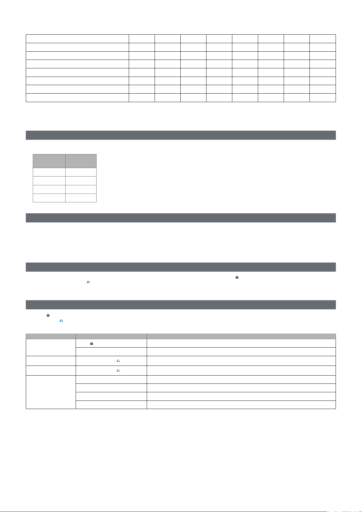
Frontal LED and selector
Frontal LED
The frontal red LED flashes proportionally to the active imported energy consumption if the selector is in - 1 - 2 position, and to the reactive inductive
energy consumption in kvarh
Frontal selector
• Lock position: the frontal selector prevents from accessing the programming mode
• 1, 2, kvarh
Application Selector position Page available
A
B, C, E, F, G, H
C
D
position: quick access to measuring pages. Each position is associated with one measuring page according to the following table:
position. Any kind of negative (exported) energy will not be managed by the front LED.
Lock
1,2,3 1
Lock, 1, 2, kvarh
Lock, 1, 2, kvarh
Lock 28
1 15
2 16
3 17
3
Can be set from 1 to 28
Can be set from 1 to 28
EM24 E1 - Instruction manual | CARLO GAVAZZI Controls SpAEM24 E1 - Instruction manual | CARLO GAVAZZI Controls SpA
15
Page 16

Maintenance and disposal
Maintenance and disposal
Cleaning
Use a slightly dampened cloth to clean the display. Do not use abrasives or solvents.
Responsibility for disposal
The product must be disposed of at the relative recycling centers specified by the government or local public authorities. Correct disposal
and recycling will contribute to the prevention of potentially harmful consequences to the environment and persons.
16
EM24 E1 - Instruction manual | CARLO GAVAZZI Controls SpA
Page 17

CARLO GAVAZZI Controls SpA
via Safforze, 8
32100 Belluno (BL) Italy
www.gavazziautomation.com
info@gavazzi-automation.com
info: +39 0437 355811
fax: +39 0437 355880
EM24 E1 - User manual
2018-06 | Copyright © 2018
Page 18

EM24 E1
Analizzatore di energia per sistemi trifase
MANUALE UTENTE
Page 19

Sommario
EM24 E1 21
Introduzione 21
Descrizione 21
UCS (Universal Conguration Software) 21
Uso di EM24 E1 22
Introduzione 22
Display 22
Impostare i parametri di rete 23
Impostare i parametri di rete via DHCP 23
Impostare i parametri di rete senza DHCP 23
Operare nell’EM24 E1 24
Operare nel menu misure/info 24
Operare nel menuimpostazioni 24
Azzerare il contatore di energia parziale 24
Impostare un parametro 25
Descrizione dei manu 26
Menu misure- pagine di misura 26
Menu informazioni 27
Impostazioni da EM24 E1 28
Impostazioni generali 28
Cose da sapere 29
Applicazioni 29
Pagine di programmazione 30
Gestire le tarie tramite comando Modbus 31
Disabilitare la gestione tarie 31
LED frontale 31
Selettore frontale 31
Manutenzione e smaltimento 32
19EM24 E1 - Manuale utente | CARLO GAVAZZI Controls SpA
Page 20

Proprietà delle informazioni
Copyright © 2018, CARLO GAVAZZI Controls SpA
Tutti i diritti riservati in tutti i paesi.
CARLO GAVAZZI Controls SpA si riserva il diritto di apportare modifiche o miglioramenti alla relativa documentazione senza
obbligo di preavviso.
Messaggi di sicurezza
Di seguito le segnalazioni legate alla sicurezza dell’utilizzatore e dell’apparecchio contenute in questo documento:
AVVISO: indica obblighi che se non ottemperati possono causare danni all’apparecchio.
ATTENZIONE! Indica una situazione rischiosa che se non evitata, può causare la perdita di dati.
IMPORTANTE: offre indicazioni essenziali al completamento del compito che non devono essere trascurate.
Avvertenze generali
Questo manuale è parte integrante del prodotto e accompagna il prodotto per tutta la sua vita. Deve essere consultato per
tutte le situazioni legate alla configurazione, all’uso e alla manutenzione. Per questo motivo deve essere sempre accessibile
agli operatori.
AVVISO: nessuno è autorizzato ad aprire l’analizzatore. TSolo il personale dell’assistenza tecnica CARLO GAVAZZI può
farlo. La protezione può essere compromessa se lo strumento viene usato in un modo non specificato dal costruttore.
Assistenza e garanzia
In caso di malfunzionamento, guasto, necessità informazioni o per acquistare componenti contattare la filiale CARLO GAVAZZI o
il distributore nel paese di appartenenza.
L’installazione e l’uso dell’analizzatore diversi da quanto indicato nelle istruzioni fornite invalidano la garanzia.
Download
Questo manuale www.productselection.net/MANUALS/UK/EM24_im_use.pdf
Istruzioni per l’installazione - EM24 www.productselection.net/MANUALS/UK/EM24_im_inst.pdf
UCS software www.productselection.net/Download/UK/ucs.zip
20 EM24 E1 - Manuale utente | CARLO GAVAZZI Controls SpA
Page 21

EM24 E1
Introduzione
EM24 è un analizzatore di energia trifase per il montaggio su guida DIN, con joystick di configurazione, selettore frontale e display LCD.
La versione con connessione diretta (AV2) consente di misurare fino a 65 A, la versione con connessione TA (AV5) consente di misurare fino
a 34875 A tramite trasformatori di corrente (uscita secondaria 5 A).
La funzione DHCP è in grado di velocizzare la messa in servizio e tutti i parametri di configurazione possono essere impostati tramite UCS.
Descrizione
AV2 AV5
Parte Descrizione
A Display LCD
B Connessioni tensione/corrente
C Joystick
D Selettore con perno per sigillo MID (blocco programmazione)
E Uscite/ingressi o porta di comunicazione
F Perni per sigillo MID (coperture di protezione incluse)
UCS (Universal Conguration Software)
UCS desktop è disponibile per il download gratuito. Può essere collegato a EM24 via Ethernet (Modbus TCP/IP).
Con UCS è possibile:
• configurare EM24 (online oppure offline)
• visualizzare lo stato del sistema a fini diagnostici e di verifica della configurazione function overview
21EM24 E1 - Manuale utente | CARLO GAVAZZI Controls SpAEM24 E1 - Manuale utente | CARLO GAVAZZI Controls SpA
Page 22

Uso di EM24 E1
Introduzione
EM24 è organizzato in quattro menu:
• menu misura e informazioni: pagine che mostrano le pagine di misura, informazioni sui parametri programmati e release firmware dello
strumento
• menu impostazioni: pagine per impostare i parametri
Display
Il display è suddiviso in 3 righe.
Simbolo Descrizione
Visualizzazione tensione fase-neutro di sistema
Visualizzazione tensione fase-fase di sistema
Visualizzazione valori massimi
User ID (Identificatore utente)
EEEE
Visualizzazione variabili di sistema
Visualizzazione variabili dmd
Overflow.
Nota: le funzioni di calcolo DMD, conta-ore e contatori di energia vengono inibite e le uscite allarme
vengono attivate. L’indicazione “EEEE” su una variabile di singola fase si estende automaticamente alla
corrispondente variabile di sistema e l’indicazione PF
viene portata a “0.000”.
22 EM24 E1 - Manuale utente | CARLO GAVAZZI Controls SpA
Page 23

Impostare i parametri di rete
Impostare i parametri di rete via DHCP
Passo Azione
1 Installare l’EM24
2 Abilitare il DHCP ed uscire con End
3 Collegare l’EM24 alla rete LAN alla quale è connesso il PC
4 Accedere alle pagine Info er visualizzare i parametri di rete assegnati
5 Avviare il software UCS e collegare l’EM24 via Connessione manuale> Modbus TCP
6 Digitare l’indirizzo IP visualizzato nelle pagine Info (vedere punto 4)
7 Accedere alle impostazioni, disabilitare il DHCP ed assegnare i parametri di rete (forniti dall’amministratore di rete)
Impostare i parametri di rete senza DHCP
Passo Azione
1 Installare l’EM24
2 Disabilitare il DHCP (disabilitato per default)
3 Collegare il PC all’EM24 via cavo Ethernet (connessione punto-punto)
Impostare le proprietà di rete del PC come segue:
• indirizzo IP statico
4
5
6 Accedere alle impostazioni e digitare i parametri di rete richiesti
7 Scollegare il cavo Ethernet e collegare l’EM24 alla rete alla quale è connesso il master Modbus
• indirizzo IP della stessa classe dell’ IP dell’ EM24, e.g. se l’IP dell’EM24 è 192.168.1.10 (di default), è possibile impostare
l’indirizzo del PC a 192.168.1.20
• Maschera di sottorete: 255.255.255.0
• Gateway: non necessario
Avviare il software UCS e collegare l’EM24 via Connessione manuale> Modbus TCP, igitare l’indirizzo IP dell’EM24 (di
default 192.168.1.10)
23EM24 E1 - Manuale utente | CARLO GAVAZZI Controls SpAEM24 E1 - Manuale utente | CARLO GAVAZZI Controls SpA
Page 24

Uso di EM24 E1
Operare nell’EM24 E1
Operare nel menu misure/info
Visualizzare la pagina
info precedente
Visualizzare la pagina misura
successiva
Visualizzare il menu
impostazioni
Visualizzare la pagina info
successiva
Visualizzare la pagina misura
precedente
Operare nel menu impostazioni
Aumentare il valore di un
parametro
Modicare/
confermare
successiva
Visualizzare la
pagina precedente
Visualizzare la pagina
Diminuire il valore di un
parametro
Azzerare il contatore di energia parziale
Passo Azione Button
1 Premere il tasto per almeno 3 secondi
2 Nella pagina PASS, inserire la password 1357
3 Confermare l’operazione
4 Nella pagina rESEt, impostare YES
5 Confermare l’operazione
24
EM24 E1 - Manuale utente | CARLO GAVAZZI Controls SpA
Page 25

Uso di EM24 E1
Passo Azione Button
6 Nella pagina EnE PrES, impostare YES
7 Confermare l’operazione
Impostare un parametro
Procedura di esempio: compe impostare Ct rAtio=20 salvare la modifica.
Passo Azione Tasto
1 Alimentare l’EM24
2 Premese il tasto per lameno 3 secondi
3 Nella pagina PASS?, selezionare la password corretta (di default 0)
4 Confermare l’operazione
5 Scorrere le pagine fino a Ct rAtio
6 Accedere alla modalità modifica
7 Selezionare 20
8 Confermare l’operazione
9 Scorrere le pagine fino a End per uscire
EM24 E1 - Manuale utente | CARLO GAVAZZI Controls SpAEM24 E1 - Manuale utente | CARLO GAVAZZI Controls SpA
25
Page 26

Uso di EM24 E1
Descrizione dei menu
Menu misure- pagine di misura
Le pagine visualizzate dipendono dall’applicazione impostata.
Pagina Misure visualizzate Descrizione
1
V
Hz
LNΣ
L1-L2-L3
L1-L2-L3
2
V
Hz
LLΣ
Tot kWh (+)
3
W
dmd
Σ
WΣ dmd max
kWh
4
A dmd max
PArt
Tot kvarh (+)
5
VAΣ dmd
VAΣ dmd max
kvarh
6
VA
PArt
Σ
kWh (+)
7
t1
W
dmd
Σ
kWh (+)
8
t2
W
dmd
Σ
kWh (+)
9
t3
W
dmd
Σ
kWh (+)
10
t4
W
dmd
Σ
kvarh (+)
11
t1
W
dmd
Σ
kvarh (+)
12
t2
W
dmd
Σ
kvarh (+)
13
t3
W
dmd
Σ
kvarh (+)
14
t4
W
dmd
Σ
kWh (+) X
15
W X
User X
kWh (+) Y
16
W Y
User Y
kWh (+) Z
17
W Z
User Z
Total kvarh (-)
18
VA
dmd
Σ
VAΣ dmd max
Total kWh (-)
19
W
dmd
Σ
WΣ dmd max
Sequenza fasi
Tensione fase-neutro di sistema
Frequenza
Sequenza fasi
Tensione fase-fase di sistema
Frequenza
Energia attiva importata totale
Potenza attiva di sistema dmd
Potenza attiva di sistema dmd max
Energia attiva
Corrente dmd massima
Energia attiva parziale
Energia reattiva importata totale
Potenza apparente di sistema dmd
Potenza apparente di sistema dmd max
Energia reattiva
Potenza apparente di sistema
Energia reattiva parziale
Energia attiva importata, tariffa 1
Potenza attiva di sistema dmd
Energia attiva importata, tariffa 2
Potenza attiva di sistema dmd
Energia attiva importata, tariffa 3
Potenza attiva di sistema dmd
Energia attiva importata, tariffa 4
Potenza attiva di sistema dmd
Energia reattiva importata, tariffa 1
dmd
W
Σ
Energia reattiva importata, tariffa 2
WΣ dmd
Energia reattiva importata, tariffa 3
WΣ dmd
Energia reattiva importata, tariffa 4
WΣ dmd
Energia attiva importata
Potenza attiva
Utente
Energia attiva importata
Potenza attiva
Utente
Energia attiva importata
Potenza attiva
Utente
Energia reattiva esportata totale
Potenza apparente di sistema dmd
Potenza apparente di sistema dmd max
Energia attiva esportata totale
Potenza attiva di sistema dmd
Potenza attiva di sistema dmd max
26
EM24 E1 - Manuale utente | CARLO GAVAZZI Controls SpA
Page 27

Congurare il sistema
20
21
22
23
24
25
26
27
28
Hours
W
Σ
PF
Σ
Hours
VAr
Σ
PF
Σ
var L1
var L2
var L3
VA L1
VA L2
VA L3
PF L1
PF L2
PF L3
W L1
W L2
W L3
A L1
A L2
A L3
V L1-2
V L2-3
V L3-1
V L1
V L2
V L3
Contaore
Potenza attiva di sistema
Fattore di potenza di sistema
Contaore
Potenza reattiva di sistema
Fattore di potenza di sistema
Potenza reattiva di fase 1
Potenza reattiva di fase 2
Potenza reattiva di fase 3
Potenza apparente di fase 1
Potenza apparente di fase 2
Potenza apparente di fase 3
Fattore di potenza di fase 1
Fattore di potenza di fase 2
Fattore di potenza di fase 3
Potenza attiva di fase 1
Potenza attiva di fase 2
Potenza attiva di fase 3
Corrente di fase 1
Corrente di fase 2
Corrente di fase 3
Tensione di fase 1-fase 2
Tensione di fase 2-fase 3
Tensione di fase 3-fase 1
Tensione di fase 1
Tensione di fase 2
Tensione di fase 3
Note: in modalità programmazione, rimane in memoria l’ultima pagina visualizzata.
Menu informazioni
Pagina Titolo pagina Informazioni visualizzate
1 IP o.o.-.- Indirizzo IP (prima parte)
2 IP -.-.o.o Indirizzo IP (seconda parte)
3 Sub o.o.-.- Maschera di sottorete (prima parte)
4 Sub -.-.o.o Maschera di sottorete (seconda parte)
5 Gateo.o.-.- Default gateway (prima parte)
6 Gate-.-.o.o Default gateway (seconda parte)
7 Port Porta Modbus TCP
8 DHCP Abilitazione DHCP
9 Info Diagnostica Ethernet
10 Ut ratio Rapporto TV
11 CT ratio Rapporto TA
12
(2-3-4-wire)
dmd (time)
13 Pulse Peso impulsi LED (numero di kWh/kvarh per impulso)
14 Year
1P/2P/3P/3Pn
Sistema
Connessione (2-3-4 fili)
Intervallo per il calcolo dei valori medi (min.)
Release firmware
Anno di produzione
EM24 E1 - Manuale utente | CARLO GAVAZZI Controls SpAEM24 E1 - Manuale utente | CARLO GAVAZZI Controls SpA
27
Page 28

Congurare il sistema
Impostazioni da EM24 E1
Impostazioni generali
Le impostazioni disponibili dipendono dall’applicazione impostata.
Titolo pagina Sotto-menu Descrizione Valori Valori di default
Cng PASS - Modica password Da 0 a 9999 0
APPLiCAt Applicazione tYP.A
User USEr 1 Utente Da 0 a 9999 1
USEr 2 Da 0 a 9999 2
USEr 3 Da 0 a 9999 3
dHCP - Abilitazione DHCP oFF/on oFF
IP Addr IP o.-.-.- Indirizzo IP Da 000 a 255 192
IP -.o.-.- Da 000 a 255 168
IP -.-.o.- Da 000 a 255 1
IP -.-.-.o Da 000 a 255 10
SUb SUb o.-.-.- Maschera di sottorete Da 000 a 255 255
SUb -.o.-.- Da 000 a 255 255
SUb -.-.o.- Da 000 a 255 255
SUb -.-.-.o Da 000 a 255 0
GAtE GAtE o.-.-.- Gateway di default Da 000 a 255 192
GAtE -.o.-.- Da 000 a 255 168
GAtE -.-.o.- Da 000 a 255 1
GAtE -.-.-.o Da 000 a 255 1
Port - Porta MODBUS TCP 502
SELECtor SELEC. 1 Pagina visualizzata in base alla
SELEC. 2 Da 1 a 28 25
SELEC. 3 Da 1 a 28 28
SELEC.LoC Da 1 a 28 3
SYS - Sistema 3P.n
Ut rAtio - Rapporto del trasformatore di tensione
Ct rAtio - Rapporto del trasformatore di corrente
P int.ti - Intervallo per il calcolo dei valori medi
FiLtEr.S - Intervallo di intervento del ltro rispetto al
FiLtEr.Co - Coefciente del ltro Da 1 a 32 2
End - Esci e salva le modiche - -
posizione del selettore tra le pagine
disponibili per ciascuna applicazione (vedere “Selettore frontale” a pagina 31)
(TV)
(TA)
(min)
fondo scala (%)
tYP.b
tYP.C
tYP.d
tYP.E
tYP.F
tYP.G
tYP.H
Da 1 a 28 1
3P.1
2P
1P
3P
Nota: MID (PFA, PFB): solo 3P.n
AV5: da 1 a 6975
AV2: N/D
AV5: da 1 a 6975
AV2: N/D
Da 1 a 30 15
Da 0 a 100 2
tYP.H
3P.n
1
1
Nota: Ut rAtio è disponibile per compatibilità con altre versioni, anche se la versione AV5 non è destinata ad essere utilizzata con trasformatori di tensione.
Dovrebbe essere quindi impostato a 1.
28
EM24 E1 - Manuale utente | CARLO GAVAZZI Controls SpA
Page 29

Cose da sapere
Cose da sapere
Gestione misure
Applicazioni
Nota: se l’applicazione selezionata prevede la funzione Easy connection, per il calcolo dell’energia attiva la potenza è sempre integrata, sia nel caso di potenza
importata che esportata. La direzione della corrente non influisce sulla misura. Se l’applicazione selezionata non prevede la funzione Easy connection, sono
disponibili sia l’energia attiva importata che quella esportata.
Applicazione Misure Easy connection
Sistema:
• sequenza fasi
A
B
C
D
E
F
• tensione fase-neutro
• frequenza
• energia attiva importata totale
• potenza attiva dmd e dmd max
Sistema:
• sequenza fasi
• tensione fase-neutro
• frequenza
• energia attiva importata totale
• potenza attiva dmd e dmd max
• energia reattiva importata totale
• potenza apparente dmd e dmd max
Sistema:
• sequenza fasi
• tensione fase-neutro
• frequenza
• energia attiva importata totale
• potenza attiva dmd e dmd max
• energia attiva e reattiva importata per tariffa
Monofase:
• energia attiva importata
• tensione
Sistema:
• sequenza fasi
• tensione fase-neutro
• frequenza
• energia attiva e reattiva importata totale
• potenza attiva dmd e dmd max
• contaore
• potenza attiva
• fattore di potenza
Sistema:
• sequenza fasi
• tensione fase-neutro
• frequenza
• energia attiva e reattiva importata totale
• potenza attiva dmd e dmd max
• tensione fase-fase
• energia attiva
• corrente dmd massima
• energia attiva parziale
• energia reattiva importata ed esportata totale
• potenza apparente, dmd e dmd max
• energia reattiva parziale
• contaore
• potenza attiva
• fattore di potenza
SÌ
SÌ
SÌ
SÌ
NO
NO
EM24 E1 - Manuale utente | CARLO GAVAZZI Controls SpAEM24 E1 - Manuale utente | CARLO GAVAZZI Controls SpA
29
Page 30

Cose da sapere
G
H
Sistema:
• sequenza fasi
• tensione fase-neutro
• frequenza
• energia attiva importata totale
• potenza attiva dmd e dmd max
• tensione fase-fase
• energia attiva
• corrente dmd massima
• energia attiva parziale
• energia reattiva importata totale
• potenza apparente, dmd e dmd max
• energia reattiva
• contaore
• potenza attiva
• potenza attiva dmd
• potenza reattiva
• fattore di potenza
• energia attiva e reattiva importata per tariffa
Monofase:
• potenza reattiva per fase
• potenza apparente per fase
• fattore di potenza per fase
• potenza attiva per fase
• corrente per fase
• tensioni linea-linea
• tensioni linea-neutro
Sistema:
• sequenza fasi
• tensione fase-neutro
• frequenza
• energia attiva e reattiva importata totale
• potenza attiva dmd e dmd max
• tensione fase-fase
• energia attiva
• corrente dmd massima
• energia attiva parziale
• energia reattiva importata ed esportata totale
• potenza apparente, dmd e dmd max
• energia reattiva
• contaore
• potenza attiva
• potenza attiva dmd
• potenza reattiva
• fattore di potenza
• energia attiva e reattiva importata per tariffa
Monofase:
• potenza reattiva per fase
• potenza apparente per fase
• fattore di potenza per fase
• potenza attiva per fase
• corrente per fase
• tensioni linea-linea
• tensioni linea-neutro
SÌ
NO
Pagine di programmazione
La tabella seguente mostra quali pagine di programmazione sono disponibili per ciascuna applicazione
Pagina Applicazione
A B C D E F G H
Modica password x x x x x x x x
Applicazione x x x x x x x x
Utente - - - x - - - Abilitazione DHCP x x x x x x x x
Indirizzo IP x x x x x x x x
Maschera di sottorete x x x x x x x x
Gateway di default x x x x x x x x
Porta MODBUS TCP x x x x x x x x
30
EM24 E1 - Manuale utente | CARLO GAVAZZI Controls SpA
Page 31

Cose da sapere
Selettore x x x x x x x x
Sistema x x x x x x x
Rapporto del trasformatore di tensione (TV) x x x x x x x x
Rapporto del trasformatore di corrente (TA) x x x x x x x x
Intervallo per il calcolo dei valori medi x x x - x x x x
Intervallo di intervento del ltro rispetto al
fondo scala (%)
Coeciente del ltro - - - - - x x x
End x x x x x x x x
- - - - - x x x
Gestione tariffe
Gestire le tarie tramite comando Modbus
Comandare il cambio tariffa scrivendo nel registro 1201Fh il valore corrispondente alla tariffa attuale in accordo alla seguente tabella:
Tariffa
attuale
T1 1
T2 2
T3 3
T4 4
Valore
registro
Disabilitare la gestione tarie
Impostare la gestione delle tariffe come disabilitata oppure scrivere nel registro 1201Fh il valore 0 (valore di default)
LED e selettore frontali
LED frontale
Il LED rosso frontale lampeggia proporzionalmente al consumo di energia attiva importata se il selettore si trova in posizione - 1 - 2, e al consumo di
energia reattiva induttiva se in posizione kvarh
Selettore frontale
• Posizione Lock : il selettore frontale impedisce l’accesso alla modalità di programmazione
• Posizione 1, 2, kvarh
Applicazione Posizione del seletore Pagina disponibile
A
B, C, E, F, G, H
C
D
: accesso rapido alle pagine di misura. Ogni posizione è associata ad una pagina di misura in base alla tabella seguente:
Lock
1,2,3 1
Lock, 1, 2, kvarh
Lock, 1, 2, kvarh
Lock 28
1 15
2 16
3 17
. Ogni tipo di energia negativa (esportata) non è gestita dal LED.
3
Selezionabile, da 1 a 28
Selezionabile, da 1 a 28
EM24 E1 - Manuale utente | CARLO GAVAZZI Controls SpAEM24 E1 - Manuale utente | CARLO GAVAZZI Controls SpA
31
Page 32

Manutenzione e smaltimento
Manutenzione e smaltimento
Pulizia
Per mantenere pulito il display usare un panno leggermente inumidito. Non usare abrasivi o solventi.
Responsabilità di smaltimento
Smaltire con raccolta differenziata tramite le strutture di raccolte indicate dal governo o dagli enti pubblici locali. Il corretto smaltimento
e il riciclaggio aiuteranno a prevenire conseguenze potenzialmente negative per l’ambiente e per le persone.
32
EM24 E1 - Manuale utente | CARLO GAVAZZI Controls SpA
Page 33

CARLO GAVAZZI Controls SpA
via Safforze, 8
32100 Belluno (BL) Italy
www.gavazziautomation.com
info@gavazzi-automation.com
info: +39 0437 355811
fax: +39 0437 355880
EM24 E1 - Manuale utente
2018-06 | Copyright © 2018
Page 34

EM24 E1
Dreiphasen-Energieanalysator
BETRIEBSANLEITUNG
Page 35

Inhaltsverzeichnis
EM24 E1 37
Einleitung 37
Beschreibung 37
UCS (Universal Conguration Software) (Kongurationssoftware) 37
Benutzung des EM24 E1 38
Einleitung 38
Anzeige 38
Netzwerkparametereinstellungen 39
Netzwerkparameter über DHCP einstellen 39
Netzwerkparameter ohne DHCP einstellen 39
Arbeiten mit EM24 E1 40
Arbeiten mit dem Messungs-/Infomenü 40
Arbeiten mit dem Einstellungsmenü 40
Setzt den partiellen Energiezähler zurück 40
Einstellen eines Parameters 41
Beschreibung der Menüs 42
Messungsmenü - Messungsseiten 42
Informationsmenü 43
Einstellungen vom EM24 E1 44
Allgemeine Einstellungen 44
Wichtige Informationen 45
Anwendungen 45
Programmierseiten 46
Tarifverwaltung über Modbus-Befehl 47
Deaktivierung der Tarifverwaltung 47
Front-LED 47
Vorderer Wahlschalter 47
Instandhaltung und Entsorgung 48
35EM24 E1 - Bedienungsanleitung | CARLO GAVAZZI Controls SpA
Page 36

Information über Eigentumsrechte
Copyright © 2018, CARLO GAVAZZI Controls SpA
Alle Rechte vorbehalten in allen Ländern.
CARLO GAVAZZI Controls SpA behält sich das Recht vor, ohne vorherige Ankündigung Änderungen oder Verbesserungen in der
entsprechenden Dokumentation vorzunehmen.
Sicherheitshinweise
Der folgende Abschnitt beschreibt die in diesem Dokument enthaltenen Warnungen in Bezug auf Benutzer- und Gerätesicherheit:
HINWEIS: Bezeichnet Bedienungsregeln, deren Nichtbeachtung zu Schäden am Gerät führen können.
VORSICHT! Bezeichnet eine riskante Situation, die Datenverlust verursachen kann, wenn sie nicht vermieden
wird.
WICHTIG: Bietet wesentliche Informationen zur Erledigung einer Aufgabe, die nicht vernachlässigt werden sollte.
Allgemeine Warnungen
Diese Anleitung ist ein integraler Bestandteil des Produkts und verbleibt bei ihm für seine gesamte Lebensdauer. Sie sollte
in allen Situationen betreffend Konfiguration, Gebrauch und Instandhaltung zu Rate gezogen werden. Deshalb sollte sie
dem Benutzer jederzeit zugänglich sein.
HINWEIS: Niemand ist autorisiert, das Analysator zu öffnen. Diese Operation ist ausschließlich dem technischen
Kundendienstpersonal von CARLO GAVAZZI vorbehalten.
Die Schutzfunktion kann beeinträchtigt werden, wenn das Instrument anders als vom Hersteller vorgesehen benutzt wird.
Kundendienst und Garantie
Bei Störungen oder Fehlern bzw. wenn Sie Auskünfte benötigen, wenden Sie sich bitte an die Niederlassung von CARLO GAVAZZI
oder den zuständigen Vertriebspartner in Ihrem Land.
Installation und Gebrauch von Analysatoren abweichend von der Beschreibung in der mitgelieferten Anleitung macht die Garantie
ungültig.
Download
Diese Anleitung www.productselection.net/MANUALS/UK/EM24_im_use.pdf
Installationsanleitung - EM24 www.productselection.net/MANUALS/UK/EM24_im_inst.pdf
UCS-Software www.productselection.net/Download/UK/ucs.zip
36 EM24 E1 - Bedienungsanleitung | CARLO GAVAZZI Controls SpA
Page 37

EM24 E1
Einleitung
EM24 ist ein Drei-Phasen-Energieanalysator für DIN-Schienenmontage mit Konfigurationsjoystick, frontseitigem Wahlschalter und LCDAnzeige.
Die Ausführung mit direktem Anschluss (AV2) ermöglicht die Messung bis zu 65 A, während die CT-Anschlussversion (AV5) die Messung bis
zu 34875 A mit Stromwandlern (5 A Sekundärausgang) erlaubt.
Die DHCP-Funktion kann die Inbetriebnahme beschleunigen, und alle Konfigurationsparameter können über die UCS eingestellt werden.
Beschreibung
AV2 AV5
Teil
Beschreibung
A LCD-Anzeige
B Spannungs-/Stromverbindungen
C Joystick
D Wahlschalter mit Stift für MID-Dichtung (Programmiersatz)
E Eingänge/Ausgänge oder Kommunikationsschnittstelle
F Stifte für MID-Dichtung (Schutzabdeckungen inbegriffen)
UCS (Universal Conguration Software) (Kongurationssoftware)
Die Arbeitsoberfläche der UCS ist frei herunterladbar. Sie kann über Ethernet (Modbus TCP/IP) mit EM24 verbunden werden.
UCS ermöglicht folgendes:
• Konfiguration EM24 (Online oder Offline)
• Anzeigen des Systemstatus für Diagnostik und zum Überprüfen der Konfiguration Funktionsüberblick
37EM24 E1 - Bedienungsanleitung | CARLO GAVAZZI Controls SpA
Page 38

Benutzung des EM24 E1
Einleitung
Der EM24 bietet zwei Menüs an:
• Messungs- und Informationsmenü: Die Seiten zeigen Messwerteseiten, Informationen über die programmierten Parameter und
Firmwarefreigabe an
• Einstellungsmenü: Die Seiten stellen die Parametereinstellungen dar
Anzeige
Die Anzeige ist in 3 Zeilen unterteilt.
Symbol Beschreibung
Anzeige der Phasen-Nullleiter-Systemspannung
Anzeige der Phasen-Phasen-Systemspannung
Anzeige der MAX-Werte
Benutzer-ID
EEEE
Anzeige der Systemvariablen
Anzeige der DMD Variablen
Overflow.
Hinweis:
sowie die Energiezählerfunktionen sind gesperrt, und die
Alarmausgänge sind eingeschaltet. Die Angabe „EEEE”
in einer Einphasen-Variable deutet automatisch auf den
Overflow-Zustand der relevanten Systemvariable hin,
und die PF-Angabe wird zu „0.000” gezwungen.
Die DMD Berechnungs-, die Stundenzähler-
38 EM24 E1 - Bedienungsanleitung | CARLO GAVAZZI Controls SpA
Page 39

Netzwerkparametereinstellungen
Netzwerkparameter über DHCP einstellen
Schritt Aktion
1 EM24 installieren
2 DHCP aktivieren und mit End verlassen
3 EM24 mit dem LAN-Netzwerk verbinden, an dem der PC angeschlossen ist
4 Zur Ansicht der zugeordneten Netzwerkparameter greifen Sie auf die Info Seiten
5 UCS-Software starten und mit EM24 über Manuelle Verbindung> Modbus TCP verbinden
6 Die auf der Info-Seite (siehe Punkt 4) angezeigte IP-Adresse eingeben
7
Greifen Sie auf die Einstellungen, deaktivieren Sie DHCP und ordnen Sie die notwendigen Netzwerkparameter zu (vom
Netzwerkadministrator vergeben)
Netzwerkparameter ohne DHCP einstellen
Schritt Aktion
1 EM24 installieren
2 DHCP deaktivieren (Standard-Einstellung)
3 Verbinden Sie den PC mit dem EM24 durch ein Ethernetkabel (Punkt-zu-Punkt Verbindung)
Die Netzwerkeigenschaften des PCs wie folgt einstellen:
• statische IP-Adresse
4
5
6 Gelangen Sie zu den Einstellungen, und geben Sie die erforderlichen Netzwerkparameter ein
• IP-Adresse der gleichen Art wie EM24, z. Bsp. falls die IP von EM24 192.168.1.10 (Standard) ist, können Sie die PCAdresse auf 192.168.1.20 einstellen
• Subnetzmaske: 255.255.255.0
• Gateway: nicht nötig
UCS-Software starten und mit EM24 über Manuelle Verbindung> Modbus TCP verbinden, die EM24 IP-Adresse eingeben (192.168.1.10 standardmäßig)
7 Ethernet-Kabel entfernen und EM24 mit dem Netzwerk verbinden, an dem der Modbus-Master angeschlossen ist
39EM24 E1 - Bedienungsanleitung | CARLO GAVAZZI Controls SpA
Page 40

Benutzung des EM24 E1
Arbeiten mit EM24 E1
Arbeiten mit dem Messungs-/Infomenü
zur vorherigen Seite zur nächsten Infoseite
zur nächsten Messungsseite
zum Einstellungsmenü
zur vorherigen Messungsseite
Arbeiten mit dem Einstellungsmenü
Parameterwert erhöhen
Bearbeiten/Bestägen
zur vorherigen Seite
Parameterwert verringern
zur nächsten Seite
Setzt den partiellen Energiezähler zurück
Schritt Aktion Taste
1 Die Taste für mindestens 3 Sekunden gedrückt halten
2
3 Operation bestätigen
4 Auf der Seite rESEt YES eingeben
5 Operation bestätigen
40
EM24 E1 - Bedienungsanleitung | CARLO GAVAZZI Controls SpA
Auf der Seite PASS das Passwort 1357 eingeben
Page 41

Benutzung des EM24 E1
Schritt Aktion Taste
6 Auf der Seite EnE PrES YES eingeben
7 Operation bestätigen
Einstellen eines Parameters
Beispielprozedur: Wie Ct rAtio=20 gesetzt und die Änderung gespeichert wird.
Schritt Aktion Taste
1 Energiezähler einschalten
2 Joystick für mindestens 3 Sekunden gedrückt halten
3 Auf der Seite PASS? das richtige Passwort eingeben (Standard 0)
4 Operation bestätigen
5 Seiten scrollen bis Ct rAtio
6 Gelangen Sie in den Bearbeitungsmodus
7 20 auswählen
8 Operation bestätigen
9 Seiten scrollen bis End, um das Menü abzuschließen
EM24 E1 - Bedienungsanleitung | CARLO GAVAZZI Controls SpA
41
Page 42

Benutzung des EM24 E1
Beschreibung der Menüs
Messungsmenü - Messungsseiten
Die angezeigten Seiten hängen von der eingestellten Anwendung ab.
Page Angezeigte Messungen Beschreibung
1
V
Hz
LNΣ
L1-L2-L3
L1-L2-L3
2
V
Hz
LLΣ
Tot kWh (+)
3
W
dmd
Σ
WΣ dmd max
kWh
4
A dmd max
PArt
Tot kvarh (+)
5
VAΣ dmd
VAΣ dmd max
kvarh
6
VA
PArt
Σ
kWh (+)
7
t1
dmd
W
Σ
kWh (+)
8
t2
W
dmd
Σ
kWh (+)
9
t3
W
dmd
Σ
kWh (+)
10
t4
W
dmd
Σ
kvarh (+)
11
t1
W
dmd
Σ
kvarh (+)
12
t2
W
dmd
Σ
kvarh (+)
13
t3
W
dmd
Σ
kvarh (+)
14
t4
W
dmd
Σ
kWh (+) X
15
W X
User X
kWh (+) Y
16
W Y
User Y
kWh (+) Z
17
W Z
User Z
Total kvarh (-)
18
dmd
VA
Σ
VAΣ dmd max
Total kWh (-)
19
W
dmd
Σ
WΣ dmd max
Phasensequenz
System Phase-Nullleiter-Spannung
Frequenz
Phasensequenz
System Phase-Phase-Spannung
Frequenz
Importierte Wirkenergie gesamt
System-Wirkleistung DMD
System-Wirkleistung DMD max.
Wirkenergie
Maximalstrom DMD
Partielle Wirkenergie
Importierte Blindenergie gesamt
System-Scheinleistung DMD
System-Scheinleistung DMD max.
Blindenergie
System-Scheinleistung
Partielle Blindenergie
Importierte Wirkenergie, Tarif 1
System-Wirkleistung DMD
Importierte Wirkenergie, Tarif 2
System-Wirkleistung DMD
Importierte Wirkenergie, Tarif 3
System-Wirkleistung DMD
Importierte Wirkenergie, Tarif 4
System-Wirkleistung DMD
Importierte Blindenergie, Tarif 1
DMD
W
Σ
Importierte Blindenergie, Tarif 2
DMD
W
Σ
Importierte Blindenergie, Tarif 3
WΣ DMD
Importierte Blindenergie, Tarif 4
WΣ DMD
Importierte Wirkenergie
Wirkleistung
Benutzer
Importierte Wirkenergie
Wirkleistung
Benutzer
Importierte Wirkenergie
Wirkleistung
Benutzer
Exportierte Blindenergie gesamt
System-Scheinleistung DMD
System-Scheinleistung DMD max.
Exportierte Wirkenergie gesamt
System-Wirkleistung DMD
System-Wirkleistung DMD max.
42
EM24 E1 - Bedienungsanleitung | CARLO GAVAZZI Controls SpA
Page 43

Systemkonguration
20
21
22
23
24
25
26
27
28
Hours
W
Σ
PF
Σ
Hours
VAr
Σ
PF
Σ
var L1
var L2
var L3
VA L1
VA L2
VA L3
PF L1
PF L2
PF L3
W L1
W L2
W L3
A L1
A L2
A L3
V L1-2
V L2-3
V L3-1
V L1
V L2
V L3
Gesamt-Betriebsstunden unter Last
System-Wirkleistung
System-Leistungsfaktor
Gesamt-Betriebsstunden unter Last
System-Blindleistung
System-Leistungsfaktor
Blindleistung Phase 1
Blindleistung Phase 2
Blindleistung Phase 3
Scheinleistung Phase 1
Scheinleistung Phase 2
Scheinleistung Phase 3
Leistungsfaktor Phase 1
Leistungsfaktor Phase 2
Leistungsfaktor Phase 3
Wirkleistung Phase 1
Wirkleistung Phase 2
Wirkleistung Phase 3
Strom Phase 1
Strom Phase 2
Strom Phase 3
Spannung Phase 1-Phase 2
Spannung Phase 2-Phase 3
Spannung Phase 3-Phase 1
Spannung Phase 1
Spannung Phase 2
Spannung Phase 3
Hinweis: Die zuletzt angezeigte Seite wird im Programmiermodus gespeichert.
Informationsmenü
Page Seitentitel Angezeigte Information
1 IP o.o.-.- IP-Adresse (erster Teil)
2 IP -.-.o.o IP-Adresse (zweiter Teil)
3 Sub o.o.-.- Subnetzmaske (erster Teil)
4 Sub -.-.o.o Subnetzmaske (zweiter Teil)
5 Gateo.o.-.- Standard-Gateway (erster Teil)
6 Gate-.-.o.o Standard-Gateway (zweiter Teil)
7 Port Modbus TCP Port
8 DHCP DHCP aktiviert
9 Info Ethernet-Diagnose
10 Ut ratio Spannungswandler-/Stromwandlerverhältnis
11 CT ratio CT-Verhältnis
12
(2-3-4-wire)
dmd (time)
13 Pulse LED Impulsgewicht (Anzahl der kWh/kvarh pro Impuls)
14 Year
1P/2P/3P/3Pn
System
Anschluss (2-3-4-Draht)
DMD Integrationszeit (Min.)
Firmwarefreigabe
Herstellungsjahr
EM24 E1 - Bedienungsanleitung | CARLO GAVAZZI Controls SpA
43
Page 44

Systemkonguration
Einstellungen vom EM24 E1
Allgemeine Einstellungen
Die verfügbaren Einstellungen hängen von der eingestellten Anwendung ab.
Seitentitel Untermenü Beschreibung Werte Standardwert
Cng PASS - Passwort ändern Von 0 bis 9999 0
APPLiCAt Anwendung tYP.A
User USEr 1 Benutzer Von 0 bis 9999 1
USEr 2 Von 0 bis 9999 2
USEr 3 Von 0 bis 9999 3
dHCP - DHCP aktiviert oFF/on oFF
IP Addr IP o.-.-.- IP-Adresse Von 000 bis 255 192
IP -.o.-.- Von 000 bis 255 168
IP -.-.o.- Von 000 bis 255 1
IP -.-.-.o Von 000 bis 255 10
SUb SUb o.-.-.- Subnetzmaske Von 000 bis 255 255
SUb -.o.-.- Von 000 bis 255 255
SUb -.-.o.- Von 000 bis 255 255
SUb -.-.-.o Von 000 bis 255 0
GAtE GAtE o.-.-.- Standard-Gateway Von 000 bis 255 192
GAtE -.o.-.- Von 000 bis 255 168
GAtE -.-.o.- Von 000 bis 255 1
GAtE -.-.-.o Von 000 bis 255 1
Port - MODBUS TCP Port 502
SELECtor SELEC. 1 Die Seite wird nach Stellung des Wahl-
SELEC. 2 Von 1 bis 28 25
SELEC. 3 Von 1 bis 28 28
SELEC.LoC Von 1 bis 28 3
SYS - System 3P.n
Ut rAtio - Spannungswandlerverhältnis (VT) AV5: von 1 bis 6975
Ct rAtio - Stromwandlerverhältnis (CT) AV5: von 1 bis 6975
P int.ti - DMD Integrationszeit (Min) Von 1 bis 30 15
FiLtEr.S - Intervall für die Filteranwendung
FiLtEr.Co - Filterkoefzient Von 1 bis 32 2
End - Beenden und speichern - -
schalters unter den verfügbaren Seiten
für jede Anwendung angezeigt (siehe
„Vorderer Wahlschalter“ auf Seite 47)
bezüglich
der Vollausschläge (%)
tYP.b
tYP.C
tYP.d
tYP.E
tYP.F
tYP.G
tYP.H
Von 1 bis 28 1
3P.1
2P
1P
3P
Hinweis: MID (PFA, PFB): nur 3P.n
AV2: N/A
AV2: N/A
Von 0 bis 100 2
tYP.H
3P.n
1
1
Hinweis: Das Ut rAtio ist zur Kompatibilität mit anderen Versionen verfügbar, obwohl die AV5 Version nicht für die Benutzung mit Spannungswandlern
vorgesehen ist. Daher soll es auf 1 eingestellt werden.
44
EM24 E1 - Bedienungsanleitung | CARLO GAVAZZI Controls SpA
Page 45

Wichtige Informationen
Wichtige Informationen
Verwaltung der Messungen
Anwendungen
Hinweis: Wenn eine Anwendung mit einfachem Anschluss ausgewählt wird, ist der Strom für die Berechnung der Wirkenergie immer integriert, sowohl bei der
importierten als auch exportierten Leistung. Die Stromrichtung beeinträchtigt nicht die Messung. Wenn eine Anwendung ohne einfachen Anschluss ausgewählt
wird, ist sowohl die importierte als auch die exportierte Wirkleistung verfügbar.
Anwendung Messungen
System:
• Phasensequenz
A
B
C
D
E
F
• Phase-Nullleiter-Spannung
• Frequenz
• importierte Wirkenergie gesamt
• Wirkleistung DMD und DMD max
System:
• Phasensequenz
• Phase-Nullleiter-Spannung
• Frequenz
• importierte Wirkenergie gesamt
• Wirkleistung DMD und DMD max
• importierte Blindenergie gesamt
• Scheinleistung DMD und DMD max
System:
• Phasensequenz
• Phase-Nullleiter-Spannung
• Frequenz
• importierte Wirkenergie gesamt
• Wirkleistung DMD und DMD max
• importierte Wirk- und Blindenergie nach Tarif
Einphasig:
• importierte Wirkenergie
• Spannung
System:
• Phasensequenz
• Phase-Nullleiter-Spannung
• Frequenz
• importierte und exportierte Wirkenergie gesamt
• Wirkleistung DMD und DMD max
• Betriebsstundenzähler
• Wirkleistung
• Leistungsfaktor
System:
• Phasensequenz
• Phase-Nullleiter-Spannung
• Frequenz
• importierte und exportierte Wirkenergie gesamt
• Wirkleistung DMD und DMD max
• Phase-Phase-Spannung
• Wirkenergie
• Maximalstrom DMD
• Partielle Wirkenergie
• importierte und exportierte Blindenergie gesamt
• Scheinleistung, DMD und DMD max
• Partielle Blindenergie
• Betriebsstundenzähler
• Wirkleistung
• Leistungsfaktor
Einfacher
Anschluss
JA
JA
JA
JA
NEIN
NEIN
EM24 E1 - Bedienungsanleitung | CARLO GAVAZZI Controls SpA
45
Page 46

Wichtige Informationen
System:
• Phasensequenz
• Phase-Nullleiter-Spannung
• Frequenz
• importierte Wirkenergie gesamt
• Wirkleistung DMD und DMD max
• Phase-Phase-Spannung
• Wirkenergie
• Maximalstrom DMD
• Partielle Wirkenergie
• importierte Blindenergie gesamt
• Scheinleistung, DMD und DMD max
• Blindenergie
G
• Betriebsstundenzähler
• Wirkleistung
• Wirkleistung DMD
• Blindleistung
• Leistungsfaktor
• importierte Wirk- und Blindenergie nach Tarif
Einphasig:
• Blindleistung pro Phase
• Scheinleistung pro Phase
• Leistungsfaktor pro Phase
• Wirkleistung pro Phase
• Strom pro Phase
• Netznennspannung
• Netz-Nullleiter-Spannung
System:
• Phasensequenz
• Phase-Nullleiter-Spannung
• Frequenz
• importierte und exportierte Wirkenergie gesamt
• Wirkleistung DMD und DMD max
• Phase-Phase-Spannung
• Wirkenergie
• Maximalstrom DMD
• Partielle Wirkenergie
• importierte und exportierte Blindenergie gesamt
• Scheinleistung, DMD und DMD max
• Blindenergie
H
• Betriebsstundenzähler
• Wirkleistung
• Wirkleistung DMD
• Blindleistung
• Leistungsfaktor
• importierte Wirk- und Blindenergie nach Tarif
Einphasig:
• Blindleistung pro Phase
• Scheinleistung pro Phase
• Leistungsfaktor pro Phase
• Wirkleistung pro Phase
• Strom pro Phase
• Netznennspannung
• Netz-Nullleiter-Spannung
JA
NEIN
Programmierseiten
Die folgende Tabelle zeigt welche Programmierseiten für jede Anwendung zur Verfügung stehen
Page Anwendung
A B C D E F G H
Passwort ändern x x x x x x x x
Anwendung x x x x x x x x
Benutzer - - - x - - - DHCP aktiviert x x x x x x x x
IP-Adresse x x x x x x x x
Subnetzmaske x x x x x x x x
Standard-Gateway x x x x x x x x
MODBUS TCP Port x x x x x x x x
46
EM24 E1 - Bedienungsanleitung | CARLO GAVAZZI Controls SpA
Page 47

Wichtige Informationen
Wahlschalter x x x x x x x x
System x x x x x x x
Spannungswandlerverhältnis x x x x x x x x
CT-Verhältnis x x x x x x x x
Durchschnittsleistung Integrationszeit x x x - x x x x
Filter S - - - - - x x x
Filter Co - - - - - x x x
End x x x x x x x x
Tarifverwaltung
Tarifverwaltung über Modbus-Befehl
Ändern Sie den Tarif durch Eingabe des Wertes, der gemäß folgender Tabelle dem aktuellen Tarif entspricht, in das Register 1201Fh:
Aktueller
Tarif
T1 1
T2 2
T3 3
T4 4
Register-
wert
Deaktivierung der Tarifverwaltung
Stellen Sie die Tarifverwaltung auf deaktiviert ein oder setzen Sie den Wert im Register 1201Fh auf 0 (Standardwert).
Front-LED und Wahlschalter
Front-LED
Die rote Front-LED blinkt proportional zum importierten Wirkenergieverbrauch falls sich der Wahlschalter in - 1 - 2 Position befindet sowie zum induktiven Blindleistungsenergieverbrauch in kvarh Position befindet. Jede Art negativer (exportierter) Energie wird nicht von der Front-LED verwaltet.
Vorderer Wahlschalter
• Lock Position: Der vordere Wahlschalter verhindert den Zugriff auf den Programmiermodus
• 1, 2, kvarh Position: Schnellzugriff auf die Messungsseiten. Jede Position steht in Verbindung mit einer Messungsseite gemäß folgender Tabelle:
Anwendung Wahlschalterposition Verfügbare Seite
A
B, C, E, F, G, H
C
D
Lock
1,2,3 1
Lock, 1, 2, kvarh
Lock, 1, 2, kvarh
Lock 28
1 15
2 16
3 17
3
Kann von 1 bis 28 eingestellt werden
Kann von 1 bis 28 eingestellt werden
EM24 E1 - Bedienungsanleitung | CARLO GAVAZZI Controls SpA
47
Page 48

Instandhaltung und Entsorgung
Instandhaltung und Entsorgung
Reinigung
Benutzen Sie ein leicht angefeuchtetes Tuch zum Reinigen des Displays. Benutzen Sie keine Scheuer- oder Lösungsmittel.
Verantwortlichkeit für Entsorgung
Dieses Produkt muss bei einem geeigneten von der Regierung oder lokalen öffentlichen Autoritäten anerkannten Recyclingbetrieb
entsorgt werden. Ordnungsgemäße Entsorgung und Recycling tragen zur Vermeidung möglicher schädlicher Folgen für Umwelt und
Personen bei.
48
EM24 E1 - Bedienungsanleitung | CARLO GAVAZZI Controls SpA
Page 49

CARLO GAVAZZI Controls SpA
via Safforze, 8
32100 Belluno (BL) Italien
www.gavazziautomation.com
info@gavazzi-automation.com
Tel.: +39 0437 355811
Fax: +39 0437 355880
EM24 E1 - Betriebsanleitung
2018-06 | Copyright © 2018
Page 50

EM24 E1
Analyseur d’énergie triphasé
MANUEL D’EMPLOI
Page 51

Sommaire
EM24 E1 53
Introduction 53
Description 53
UCS (Logiciel de conguration universelle) 53
Utilisation EM24 E1 54
Introduction 54
Achage 54
Configuration des paramètres du réseau 55
Paramétrage du réseau via DHCP 55
Paramétrage du réseau sans DHCP 55
Travailler avec l’EM24 E1 56
Travailler avec le menu mesures/infos 56
Travailler avec le menu paramètres 56
Réinitialiser le compteur d’énergie partiel 56
Congurer un paramètre 57
Description du menu 58
Menu Mesures - pages mesures 58
Menu informations 59
Paramètres d’EM24 E1 60
Paramètres généraux 60
Informations essentielles 61
Applications 61
Pages de programmation 62
Gérer les tarifs via la commande Modbus 63
Désactivation de la gestion tarifaire 63
LED frontale 63
Sélecteur frontal 63
Entretien et élimination 64
51EM24 E1 - Manuel d’instructions | CARLO GAVAZZI Controls SpA
Page 52

Propriété des informations
Copyright © 2018, CARLO GAVAZZI Controls SpA
Tous droits réservés dans tous les pays.
CARLO GAVAZZI Controls SpA se réserve le droit d’apporter des modifications ou des améliorations à la documentation relative
sans préavis.
Messages de sécurité
La section suivante décrit les avertissements relatifs à la sécurité de l’utilisateur et du dispositif inclus dans ce document :
AVIS : indique les obligations qui, si non observées, peuvent entraîner l’endommagement du dispositif.
ATTENTION! Indique une situation de risque qui, si elle n’est pas évitée, peut entraîner la perte de données.
IMPORTANT : fournit des informations essentielles pour compléter la tâche qui ne doivent pas être négligées.
Avertissements généraux
Ce manuel fait partie intégrante du produit et l’accompagne pendant toute sa durée de vie. Il doit être consulté pour toutes
les situations liées à la configuration, et à l’entretien. Pour cette raison, il devra toujours être accessible aux opérateurs.
AVERTISSEMENT : personne n’est autorisé à ouvrir l’analyseur. Cette opération est réservée exclusivement au personnel
du service technique CARLO GAVAZZI.
La protection peut être compromise si l’instrument est utilisé d’une manière non spécifiée par le fabricant.
Entretien et garantie
En cas de dysfonctionnement, de panne ou de besoin d’informations, contactez la filiale ou le distributeur CARLO GAVAZZI de
votre pays.
L’installation et l’utilisation d’analyseurs autres que ceux indiqués dans les instructions fournies annulent la garantie.
Télécharger
Ce manuel www.productselection.net/MANUALS/UK/EM24_im_use.pdf
Instructions d’installation - EM24 www.productselection.net/MANUALS/UK/EM24_im_inst.pdf
logiciel UCS www.productselection.net/Download/UK/ucs.zip
52 EM24 E1 - Manuel d’instructions | CARLO GAVAZZI Controls SpA
Page 53

EM24 E1
Introduction
L’EM24 est un analyseur d’énergie triphasé pour montage sur rail DIN avec joystick de configuration, sélecteur frontal et écran à cristaux
liquides.
La version à connexion directe (AV2) permet de mesurer jusqu’à 65 A, la version à connexion CT (AV5) permet de mesurer jusqu’à 34875 A au
moyen de transformateurs de courant (sortie secondaire 5 A).
La fonction DHCP est capable d’accélérer la mise en service et tous les paramètres de configuration peuvent être configurés via UCS.
Description
AV2 AV5
Pièce
Description
A Affichage LCD
B Connexions tension/courants
C Joystick
D Sélecteur avec broche pour scellé MID (bloc de programmation)
E Entrées/sorties ou port de communication
F Broches pour scellé MID (couvercles de protection inclus)
UCS (Logiciel de conguration universelle)
Le bureau UCS est disponible en téléchargement gratuit. Il peut être connecté à l’EM24 via Ethernet (Modbus TCP/IP).
Ce qui suit est possible avec UCS :
• configurer l’EM24 (en ligne ou hors ligne)
• afficher l’état du système pour les diagnostics et les vérifications de configuration vue d’ensemble de la fonction
53EM24 E1 - Manuel d’instructions | CARLO GAVAZZI Controls SpA
Page 54

Utilisation EM24 E1
Introduction
EM24 est organisé en deux menus :
• menu de mesure et d’information : pages d’affichage des pages de mesure, des informations relatives aux paramètres programmés et de
la version du micrologiciel de l’instrument
• menu paramètres : pages utilisées pour définir les paramètres
Achage
L’écran est réparti en 3 lignes.
Symbole
EEEE
Description
Affichage de la tension simple
Affichage de la tension système phase à phase
Affichage des valeurs maximales
Identifiant utilisateur
Affichage des variables système
Affichage des variables dmd
Surcharge.
Remarque :
d’heures et des compteurs d’énergie sont bloquées et
les sorties d’alarme sont activées. L’indication « EEEE »
dans une variable monophasé implique automatiquement la condition de surcharge de la variable système
en question, et l’indication PF est forcée sur « 0,000 ».
les fonctions de calcul DMD, du compteur
54 EM24 E1 - Manuel d’instructions | CARLO GAVAZZI Controls SpA
Page 55

Configuration des paramètres du réseau
Paramétrage du réseau via DHCP
Étape Action
1 Installer l’EM24
2 Activer le DHCP et quitter sortir à l’aide de l’option Fin
3 Connecter l’EM24 au réseau LAN auquel le PC est connecté
4 Accéder aux pages Infos pour afficher les paramètres réseau assignés
5 Démarrer le logiciel UCS et se connecter au EM24 via Connexion manuelle > Modbus TCP
6 Saisir l’adresse IP affichée sur la page Infos (voir point 4)
7 Accéder aux paramètres, désactiver DHCP et attribuer les paramètres réseau requis (attribués par l’administrateur réseau)
Paramétrage du réseau sans DHCP
Étape Action
1 Installer l’EM24
2 Désactiver DHCP (réglage par défaut)
3 Connecter le PC à l’EM24 par le câble Ethernet (connexion point à point)
Régler les propriétés de réseau du PC comme suit :
• adresse IP statique
4
5
6 Accéder aux paramètres et saisir les paramètres réseau requis
7 Débrancher le câble Ethernet et connecter l’EM24 au réseau auquel le maître Modbus est connecté
• Adresse IP de la même classe que l’EM24, par exemple si l’IP de l’EM24 est 192.168.1.10 (par défaut), vous pouvez définir
l’adresse du PC sur 192.168.1.20
• Masque de sous-réseau : 255.255.255.0
• Passerelle : pas nécessaire
Démarrer le logiciel UCS et se connecter à l’EM24 via Connexion manuelle> Modbus TCP, saisir l’adresse IP de l’EM24
(192.168.1.10 par défaut)
55EM24 E1 - Manuel d’instructions | CARLO GAVAZZI Controls SpA
Page 56

Utilisation EM24 E1
Travailler avec l’EM24 E1
Travailler avec le menu mesures/infos
vers la page de mesure suivante
vers la page d’infos précédente vers la page d’infos suivante
vers la page de mesure précédente
vers le menu paramètres
Travailler avec le menu paramètres
augmenter la valeur d’un paramètre
modier/conrmer
vers la page précédente
diminuer la valeur d’un paramètre
vers la page suivante
Réinitialiser le compteur d’énergie partiel
Étape Action Bouton
1 Appuyer sur le bouton pendant au moins 3 secondes
2
3 Confirmer l’opération
4 Sur la page rESEt, régler sur YES
5 Confirmer l’opération
56
EM24 E1 - Manuel d’instructions | CARLO GAVAZZI Controls SpA
Sur la page PASS, sélectionner le mot de passe 1357
Page 57

Utilisation EM24 E1
Étape Action Bouton
6 Sur la page EnE PrES, régler sur YES
7 Confirmer l’opération
Congurer un paramètre
Exemple de procédure : comment configurer Ct rAtio=20 et enregistrer les modifications.
Étape Action Bouton
1 Mettre l’analyseur d’énergie sous tension
2 Appuyer sur le joystick pendant au moins 3 secondes
3 Sur la page PASS?, sélectionner le bon mot de passe (0 par défaut)
4 Confirmer l’opération
5 Faire défiler les pages jusqu’à Ct rAtio
6 Accéder au mode d’édition
7 Sélectionner 20
8 Confirmer l’opération
9 Faire défiler les pages jusqu’à Fin pour quitter
EM24 E1 - Manuel d’instructions | CARLO GAVAZZI Controls SpA
57
Page 58

Utilisation EM24 E1
Description du menu
Menu Mesures - pages mesures
Les pages affichées dépendent de l’ensemble de l’application.
Page Mesures affichées Description
1
V
Hz
LNΣ
L1-L2-L3
L1-L2-L3
2
V
Hz
LLΣ
Tot kWh (+)
3
W
dmd
Σ
WΣ dmd max
kWh
4
A dmd max
PArt
Tot kvarh (+)
5
VAΣ dmd
VAΣ dmd max
kvarh
6
VA
PArt
Σ
kWh (+)
7
t1
dmd
W
Σ
kWh (+)
8
t2
W
dmd
Σ
kWh (+)
9
t3
W
dmd
Σ
kWh (+)
10
t4
W
dmd
Σ
kvarh (+)
11
t1
W
dmd
Σ
kvarh (+)
12
t2
W
dmd
Σ
kvarh (+)
13
t3
W
dmd
Σ
kvarh (+)
14
t4
W
dmd
Σ
kWh (+) X
15
W X
User X
kWh (+) Y
16
W Y
User Y
kWh (+) Z
17
W Z
User Z
Total kvarh (-)
18
VA
dmd
Σ
VAΣ dmd max
Total kWh (-)
19
W
dmd
Σ
WΣ dmd max
Séquence de phase
Tension phase-neutre système
Fréquence
Séquence de phase
Tension phase-phase système
Fréquence
Énergie active importée totale
Puissance active système dmd
Puissance active système dmd max
Énergie active
Courant dmd maximal
Énergie active partielle
Énergie réactive importée totale
Puissance apparente système dmd
Puissance apparente système dmd max
Énergie réactive
Puissance apparente système
Énergie réactive partielle
Énergie active importée, tarif 1
Puissance active système dmd
Énergie active importée, tarif 2
Puissance active système dmd
Énergie active importée, tarif 3
Puissance active système dmd
Énergie active importée, tarif 4
Puissance active système dmd
Énergie réactive importée, tarif 1
dmd
W
Σ
Énergie réactive importée, tarif 2
dmd
W
Σ
Énergie réactive importée, tarif 3
WΣ dmd
Énergie réactive importée, tarif 4
WΣ dmd
Énergie active importée
Puissance active
Utilisateur
Énergie active importée
Puissance active
Utilisateur
Énergie active importée
Puissance active
Utilisateur
Énergie réactive exportée totale
Puissance apparente système dmd
Puissance apparente système dmd max
Énergie active exportée totale
Puissance active système dmd
Puissance active système dmd max
58
EM24 E1 - Manuel d’instructions | CARLO GAVAZZI Controls SpA
Page 59

Congurer le système
20
21
22
23
24
25
26
27
28
Hours
W
Σ
PF
Σ
Hours
VAr
Σ
PF
Σ
var L1
var L2
var L3
VA L1
VA L2
VA L3
PF L1
PF L2
PF L3
W L1
W L2
W L3
A L1
A L2
A L3
V L1-2
V L2-3
V L3-1
V L1
V L2
V L3
Total heures de fonctionnement de la charge
Puissance active système
Facteur de puissance système
Total heures de fonctionnement de la charge
Puissance réactive système
Facteur de puissance système
Puissance réactive phase 1
Puissance réactive phase 2
Puissance réactive phase 3
Puissance apparente phase 1
Puissance apparente phase 2
Puissance apparente phase 3
Facteur de puissance phase 1
Facteur de puissance phase 2
Facteur de puissance phase 3
Puissance active phase 1
Puissance active phase 2
Puissance active phase 3
Courant phase 1
Courant phase 2
Courant phase 3
Tension phase 1-phase 2
Tension phase 2-phase 3
Tension phase 3-phase 1
Tension de phase 1
Tension de phase 2
Tension de phase 3
Remarque : en mode de programmation, la dernière page affichée est stockée.
Menu informations
Page Titre page Informations affichées
1 IP o.o.-.- Adresse IP (première partie)
2 IP -.-.o.o Adresse IP (deuxième partie)
3 Sub o.o.-.- Masque de sous-réseau (première partie)
4 Sub -.-.o.o Masque de sous-réseau (deuxième partie)
5 Gateo.o.-.- Passerelle par défaut (première partie)
6 Gate-.-.o.o Passerelle par défaut (deuxième partie)
7 Port Port Modbus TCP
8 DHCP Activation du DHCP
9 Info Diagnostic Ethernet
10 Ut ratio Rapport transformateur de tension (TT)/de puissance (TP)
11 CT ratio Rapport CT
12
(2-3-4-wire)
dmd (time)
13 Pulse Poids d’impulsion LED (Nombre de kWh/kvarh par impulsion)
14 Year
1P/2P/3P/3Pn
Système
Connexion (à 2-3-4 fils)
Temps d’intégration dmd (min.)
Version du micrologiciel
Année de production
EM24 E1 - Manuel d’instructions | CARLO GAVAZZI Controls SpA
59
Page 60

Congurer le système
Paramètres d’EM24 E1
Paramètres généraux
Les paramètres disponibles dépendent de l’ensemble de l’application.
Titre page Sous-me-nuDescription Valeur Valeur par
Cng PASS - Changer le mot de passe De 0 à 9999 0
APPLiCAt Application tYP.A
User USEr 1 Utilisateur De 0 à 9999 1
USEr 2 De 0 à 9999 2
USEr 3 De 0 à 9999 3
dHCP - Activation du DHCP oFF/on oFF
IP Addr IP o.-.-.- Adresse IP De 000 à 255 192
IP -.o.-.- De 000 à 255 168
IP -.-.o.- De 000 à 255 1
IP -.-.-.o De 000 à 255 10
SUb SUb o.-.-.- Masque de sous-réseau De 000 à 255 255
SUb -.o.-.- De 000 à 255 255
SUb -.-.o.- De 000 à 255 255
SUb -.-.-.o De 000 à 255 0
GAtE GAtE o.-.-.- Passerelle par défaut De 000 à 255 192
GAtE -.o.-.- De 000 à 255 168
GAtE -.-.o.- De 000 à 255 1
GAtE -.-.-.o De 000 à 255 1
Port - Port MODBUS TCP 502
SELECtor SELEC. 1 Page afchée selon la position du
SELEC. 2 De 1 à 28 25
SELEC. 3 De 1 à 28 28
SELEC.LoC De 1 à 28 3
SYS - Système 3P.n
Ut rAtio - Rapport transformateur de tension (TT) AV5 : de 1 à 6975
Ct rAtio - Rapport de transformateur courant (CT) AV5 : de 1 à 6975
P int.ti - Temps d’intégration dmd (min.) De 1 à 30 15
FiLtEr.S - Intervalle d’intervention du ltre par
FiLtEr.Co - Coefcient du ltre De 1 à 32 2
End - Quitter et enregistrer - -
sélecteur parmi les pages disponibles
pour chaque application (voir «Sélecteur
frontal» à la page 63)
rapport à
la pleine échelle (%)
tYP.b
tYP.C
tYP.d
tYP.E
tYP.F
tYP.G
tYP.H
De 1 à 28 1
3P.1
2P
1P
3P
Remarque : MID (PFA, PFB) : uniquement 3P.n
AV2 : S.O.
AV2 : S.O.
De 0 à 100 2
défaut
tYP.H
3P.n
1
1
Remarque : la valeur Ut rAtio est disponible pour assurer la compatibilité avec les autres versions même si la version AV5 n’est pas destinée à être utilisée avec
des transformateurs de tension. Elle doit donc être réglée sur 1.
60
EM24 E1 - Manuel d’instructions | CARLO GAVAZZI Controls SpA
Page 61

Informations essentielles
Informations essentielles
Gestion des mesures
Applications
Remarque : si une application avec une connexion facile est sélectionnée, pour le calcul de l’énergie active, la puissance est toujours intégrée, à la fois dans le
cas de l’alimentation importée et exportée. La direction actuelle n’a pas d’incidence sur la mesure. Si une application sans connexion facile est sélectionnée, les
alimentations active importée et exportée sont disponibles.
Application Mesures
Système :
• séquence de phase
A
B
C
D
E
F
• tension phase-neutre
• fréquence
• énergie active importée totale
• puissance active dmd et dmd max
Système :
• séquence de phase
• tension phase-neutre
• fréquence
• énergie active importée totale
• puissance active dmd et dmd max
• énergie réactive importée totale
• puissance apparente dmd et dmd max
Système :
• séquence de phase
• tension phase-neutre
• fréquence
• énergie active importée totale
• puissance active dmd et dmd max
• énergie importée active et réactive par tarif
Monophasé:
• énergie active importée
• tension
Système :
• séquence de phase
• tension phase-neutre
• fréquence
• énergie active importée et exportée totale
• puissance active dmd et dmd max
• compte-heures
• puissance active
• facteur de puissance
Système :
• séquence de phase
• tension phase-neutre
• fréquence
• énergie active importée et exportée totale
• puissance active dmd et dmd max
• tension phase-phase
• énergie active
• courant dmd maximal
• énergie active partielle
• énergie réactive importée et exportée totale
• puissance apparente, dmd et dmd max
• énergie réactive partielle
• compte-heures
• puissance active
• facteur de puissance
Connexion
simple
OUI
OUI
OUI
OUI
NO
NO
EM24 E1 - Manuel d’instructions | CARLO GAVAZZI Controls SpA
61
Page 62

Informations essentielles
Système :
• séquence de phase
• tension phase-neutre
• fréquence
• énergie active importée totale
• puissance active dmd et dmd max
• tension phase-phase
• énergie active
• courant dmd maximal
• énergie active partielle
• énergie réactive importée totale
• puissance apparente, dmd et dmd max
• énergie réactive
G
• compte-heures
• puissance active
• puissance active dmd
• puissance réactive
• facteur de puissance
• énergie importée active et réactive par tarif
Monophasé:
• puissance réactive par phase
• puissance apparente par phase
• facteur de puissance par phase
• puissance active par phase
• courant par phase
• tensions ligne-ligne
• tensions ligne-neutre
Système :
• séquence de phase
• tension phase-neutre
• fréquence
• énergie active importée et exportée totale
• puissance active dmd et dmd max
• tension phase-phase
• énergie active
• courant dmd maximal
• énergie active partielle
• énergie réactive importée et exportée totale
• puissance apparente, dmd et dmd max
• énergie réactive
H
• compte-heures
• puissance active
• puissance active dmd
• puissance réactive
• facteur de puissance
• énergie importée active et réactive par tarif
Monophasé:
• puissance réactive par phase
• puissance apparente par phase
• facteur de puissance par phase
• puissance active par phase
• courant par phase
• tensions ligne-ligne
• tensions ligne-neutre
OUI
NO
Pages de programmation
Le tableau ci-dessous ache les pages de programmation disponibles pour chaque application
Page Application
A B C D E F G H
Changer le mot de passe x x x x x x x x
Application x x x x x x x x
Utilisateur - - - x - - - -
Activation du DHCP x x x x x x x x
Adresse IP x x x x x x x x
Masque de sous-réseau x x x x x x x x
Passerelle par défaut x x x x x x x x
Port MODBUS TCP x x x x x x x x
62
EM24 E1 - Manuel d’instructions | CARLO GAVAZZI Controls SpA
Page 63

Informations essentielles
Sélecteur x x x x x x x x
Système x x x x x x x
Rapport transformateur de tension x x x x x x x x
Rapport CT x x x x x x x x
Temps d’intégration de puissance moyenne x x x - x x x x
Filtre S - - - - - x x x
Filtre Co - - - - - x x x
Fin x x x x x x x x
Gestion tarifaire
Gérer les tarifs via la commande Modbus
Modifier le tarif en entrant la valeur correspondant au tarif actuel selon le tableau suivant dans le registre 1201Fh :
Tarif actuel
T1 1
T2 2
T3 3
T4 4
Valeur de
registre
Désactivation de la gestion tarifaire
Paramétrer la gestion des tarifs comme désactivée ou saisir 0 (valeur par défaut) dans le registre 1201Fh.
LED frontale et sélecteur
LED frontale
La LED rouge frontale clignote proportionnellement à la consommation d’énergie importée active si le sélecteur est en position 1 - 2 , et à la consomma-
tion d’énergie réactive à induction en position kvarh
Sélecteur frontal
• Position Verrouiller : le sélecteur frontal empêche d’accéder au mode de programmation
• Position 1, 2, kvarh : accès rapide aux pages de mesure. Chaque position est associée à une seule page de mesure conformément au tableau suivant :
Application Position du sélecteur Page disponible
A
B, C, E, F, G, H
C
D
Verrouiller
1,2,3 1
Verrouiller, 1, 2, kvarh
Verrouiller, 1, 2, kvarh
Verrouiller 28
1 15
2 16
3 17
. La LED frontale ne gère pas tous les types d’énergie (exporté) négative.
3
Peut être réglée de 1 à 28
Peut être réglée de 1 à 28
EM24 E1 - Manuel d’instructions | CARLO GAVAZZI Controls SpA
63
Page 64

Entretien et élimination
Entretien et élimination
Nettoyage
Utiliser un chiffon humide pour nettoyer l’afficheur. Ne pas utiliser d’abrasifs ou de solvants.
Responsabilité de l’élimination
Le produit doit être éliminé dans les déchetteries spécifiés par le gouvernement ou les autorités locales. Une élimination et un recyclage
corrects contribueront à prévenir des conséquences potentiellement nuisibles pour l’environnement et les personnes.
64
EM24 E1 - Manuel d’instructions | CARLO GAVAZZI Controls SpA
Page 65

CARLO GAVAZZI Controls SpA
via Safforze, 8
32100 Belluno (BL) Italy
www.gavazziautomation.com
info@gavazzi-automation.com
info : +39 0437 355811
fax : +86 755 355880
EM24 E1 - Manuel d’emploi
2018-06 | Copyright © 2018
Page 66

EM24 E1
Analizador de energía trifásico
INSTRUCCIONES DE USO
Page 67

Contenido
EM24 E1 69
Introducción 69
Descripción 69
UCS (software de conguración universal) 69
Uso del EM24 E1 70
Introducción 70
Display 70
Ajuste de los parámetros de la red 71
Ajuste de los parámetros de red a través de DHCP 71
Ajuste de los parámetros de red sin DHCP 71
Operaciones con el EM24 E1 72
Operaciones con el menú de medición/información 72
Operaciones con el menú de conguración 72
Reinicio del medidor de la energía parcial 72
Establecimiento de un parámetro 73
Descripción del menú 74
Menú de medición - páginas de medición 74
Menú de información 75
Ajustes desde EM24 E1 76
Ajustes generales 76
Información esencial 77
Aplicaciones 77
Páginas de programación 78
Gestión de tarifas a través de un comando Modbus 79
Inhabilitación de la gestión de tarifas 79
LED frontal 79
Selector frontal 79
Mantenimiento y eliminación 80
67EM24 E1 - Manual de instrucciones | CARLO GAVAZZI Controls SpA
Page 68

Información sobre propiedad
Copyright © 2018, CARLO GAVAZZI Controls SpA
Todos los derechos reservados en todos los países.
CARLO GAVAZZI Controls SpA se reserva el derecho a realizar modificaciones o mejoras en la documentación relativa sin
obligación de aviso previo.
Mensajes de seguridad
La siguiente sección describe las advertencias relacionadas con la seguridad de los usuarios y los dispositivos incluidos en este
documento:
ADVERTENCIA: indica obligaciones que si no se cumplen pueden provocar daños en el dispositivo.
¡CUIDADO! Indica una situación de riesgo que, si no se evita, puede provocar pérdidas de datos.
IMPORTANTE: proporciona información esencial sobre la conclusión de una tarea que no debe pasarse por alto.
Advertencias generales
Este manual forma parte integral del producto y debe acompañarlo a lo largo de toda su vida útil. Debe consultarse para
todo lo que tenga que ver con su configuración, uso y mantenimiento. Por este motivo, los operadores deben disponer de
acceso a él en todo momento.
ADVERTENCIA: nadie está autorizado a abrir el analizador. Esta operación está exclusivamente reservada para el
personal de servicio técnico de CARLO GAVAZZI.
El uso del instrumento de un modo no especificado por el fabricante podría afectar a la protección.
Reparación y garantía
Si se producen fallos o anomalías en el funcionamiento o quiere solicitar información, póngase en contacto con la filial o distribuidor
de CARLO GAVAZZI de su país.
Cualquier instalación o uso de los analizadores que no se ajuste a las instrucciones facilitadas invalidará la garantía.
Descargar
Este manual www.productselection.net/MANUALS/UK/EM24_im_use.pdf
Instrucciones de instalación - EM24 www.productselection.net/MANUALS/UK/EM24_im_inst.pdf
Software UCS www.productselection.net/Download/UK/ucs.zip
68 EM24 E1 - Manual de instrucciones | CARLO GAVAZZI Controls SpA
Page 69

EM24 E1
Introducción
El EM24 es un analizador de energía trifásico para instalación en carril DIN con configuración de palanca de mando, selector frontal y pantalla
LCD.
La versión para conexión directa (AV2) permite medir hasta 65 A, la versión para conexión CT (AV5) permite medir hasta 34875 A a través de
transformadores de corriente (salida secundaria 5 A).
La función DHCP permite acelerar la puesta en servicio y todos los parámetros de configuración se pueden establecer mediante UCS.
Descripción
AV2 AV5
Parte
Descripción
A Pantalla LCD
B Conexiones de tensión/intensidad
C Palanca de mando
D Selector con patilla para cierre MID (bloque de programación)
E Entradas/salidas o puerto de comunicación
F Patillas para cierre MID (cubiertas de protección incluidas)
UCS (software de conguración universal)
El software UCS de escritorio se encuentra disponible para su descarga de manera gratuita. Se puede conectar al EM24 a través de Ethernet
(Modbus TCP/IP) .
El UCS permite llevar a cabo estas acciones:
• configurar el EM24 (en línea o sin conexión)
• ver el estado del sistema con fines de diagnóstico y comprobación de la configuración descripción general de la función
69EM24 E1 - Manual de instrucciones | CARLO GAVAZZI Controls SpA
Page 70

Uso del EM24 E1
Introducción
El EM24 se organiza en dos menús:
• menú de información y medición: páginas utilizadas para visualizar las páginas de medición, la información relevante para los parámetros
programados y la versión del firmware del instrumento
• menú de ajustes: páginas utilizadas para configurar los parámetros
Display
La pantalla se divide en 3 líneas.
Símbolo
EEEE
Descripción
Visualización de la tensión del sistema fase-a-neutro
Visualización de la tensión del sistema fase-a-fase
Visualización de los valores máx.
Id. del usuario
Visualización de las variables del sistema
Visualización de las variables dmd
Desbordamiento.
las funciones del cálculo DMD, el contador horario
Nota:
y los medidores de energía se han inhibido y las salidas
de alarma se han activado. La indicación “EEEE” en
una variable monofásica implica automáticamente la
condición de desbordamiento de la variable del sistema
en cuestión y la indicación PF se fuerza a “0.000”.
70 EM24 E1 - Manual de instrucciones | CARLO GAVAZZI Controls SpA
Page 71

Ajuste de los parámetros de la red
Ajuste de los parámetros de red a través de DHCP
Paso Acción
1 Instale el EM24
2 Habilite la función DHCP y salga con End
3 Conecte el EM24 a la red LAN a la que esté conectado el PC
4 Acceda a las páginas Info para ver los parámetros de red asignados
5 Inicie el software UCS y conéctelo al EM24 a través de Manual connection> Modbus TCP
6 Introduzca la dirección IP que aparece en la página Info (véase el punto 4)
7
Acceda a los ajustes, inhabilite DHCP y asigne los parámetros de red necesarios (asignados por el administrador de la
red)
Ajuste de los parámetros de red sin DHCP
Paso Acción
1 Instale el EM24
2 Inhabilite DHCP (ajuste predeterminado)
3 Conecte el PC al EM24 a través del cable Ethernet (conexión de punto a punto)
Configure las propiedades de la red del PC de este modo:
• Dirección IP estática
4
5
6 Acceda a los ajustes e introduzca los parámetros de red necesarios
• Dirección IP de la misma clase que el EM24; por ejemplo, si la IP del EM24 es 192.168.1.10 (predeterminada), puede
configurar la dirección del PC como 192.168.1.20
• Máscara de subred: 255.255.255.0
• Pasarela: no es necesaria
Inicie el software UCS y conecte con el EM24 a través de Manual connection> Modbus TCP; introduzca la dirección IP
del EM24 (192.168.1.10 por defecto)
7 Desconecte el cable Ethernet y conecte el EM24 a la red a la que esté conectado el maestro Modbus
71EM24 E1 - Manual de instrucciones | CARLO GAVAZZI Controls SpA
Page 72

Uso del EM24 E1
Operaciones con el EM24 E1
Operaciones con el menú de medición/información
a la siguiente página de medición
al menú de ajustes
a la página de información
anterior
a la página de medición anterior
Operaciones con el menú de conguración
incrementar un valor del parámetro
a la página anterior
a la siguiente página de
información
editar/conrmar
a la siguiente página
disminuir un valor del parámetro
Reinicio del medidor de la energía parcial
Paso Acción Botón
1 Pulse el botón durante un mínimo de 3 segundos
2 En la página PASS, configure la contraseña 1357
3 Confirmar operación
4 En la página rESEt, configure YES
5 Confirmar operación
72
EM24 E1 - Manual de instrucciones | CARLO GAVAZZI Controls SpA
Page 73

Uso del EM24 E1
Paso Acción Botón
6 En la página EnE PrES, configure YES
7 Confirmar operación
Establecimiento de un parámetro
Procedimiento de ejemplo: cómo configurar Ct rAtio=20 y guardar los cambios.
Paso Acción Botón
1 Encienda el analizador de energía
2 Pulse la palanca de mando durante un mínimo de 3 segundos
3 En la página PASS?, seleccione la contraseña correcta (valor predeterminado 0)
4 Confirmar operación
5 Recorra las páginas hasta llegar a Ct rAtio
6 Acceda al modo de edición
7 Seleccione 20
8 Confirmar operación
9 Recorra las páginas hasta llegar a End para salir
EM24 E1 - Manual de instrucciones | CARLO GAVAZZI Controls SpA
73
Page 74

Uso del EM24 E1
Descripción del menú
Menú de medición - páginas de medición
Las páginas mostradas dependerán del conjunto de la aplicación.
Page Mediciones mostradas Descripción
1
V
Hz
LNΣ
L1-L2-L3
L1-L2-L3
2
V
Hz
LLΣ
Tot kWh (+)
3
W
dmd
Σ
WΣ dmd max
kWh
4
A dmd max
PArt
Tot kvarh (+)
5
VAΣ dmd
VAΣ dmd max
kvarh
6
VA
PArt
Σ
kWh (+)
7
t1
dmd
W
Σ
kWh (+)
8
t2
W
dmd
Σ
kWh (+)
9
t3
W
dmd
Σ
kWh (+)
10
t4
W
dmd
Σ
kvarh (+)
11
t1
W
dmd
Σ
kvarh (+)
12
t2
W
dmd
Σ
kvarh (+)
13
t3
W
dmd
Σ
kvarh (+)
14
t4
W
dmd
Σ
kWh (+) X
15
W X
User X
kWh (+) Y
16
W Y
User Y
kWh (+) Z
17
W Z
User Z
Total kvarh (-)
18
VA
dmd
Σ
VAΣ dmd max
Total kWh (-)
19
W
dmd
Σ
WΣ dmd max
Secuencia de fase
Tensión fase-neutro del sistema
Frecuencia
Secuencia de fase
Tensión fase-fase del sistema
Frecuencia
Energía activa consumida total
Potencia activa del sistema dmd
Potencia activa del sistema dmd máx.
Energía activa
Intensidad dmd máx.
Energía activa parcial
Energía reactiva consumida total
Potencia aparente del sistema dmd
Potencia aparente del sistema dmd máx.
Energía reactiva
Potencia aparente del sistema
Energía reactiva parcial
Energía activa consumida, tarifa 1
Potencia activa del sistema dmd
Energía activa consumida, tarifa 2
Potencia activa del sistema dmd
Energía activa consumida, tarifa 3
Potencia activa del sistema dmd
Energía activa consumida, tarifa 4
Potencia activa del sistema dmd
Energía reactiva consumida, tarifa 1
dmd
W
Σ
Energía reactiva consumida, tarifa 2
dmd
W
Σ
Energía reactiva consumida, tarifa 3
WΣ dmd
Energía reactiva consumida, tarifa 4
WΣ dmd
Energía activa consumida
Potencia activa
Usuario
Energía activa consumida
Potencia activa
Usuario
Energía activa consumida
Potencia activa
Usuario
Energía reactiva generada total
Potencia aparente del sistema dmd
Potencia aparente del sistema dmd máx.
Energía activa generada total
Potencia activa del sistema dmd
Potencia activa del sistema dmd máx.
74
EM24 E1 - Manual de instrucciones | CARLO GAVAZZI Controls SpA
Page 75

Conguración del sistema
20
21
22
23
24
25
26
27
28
Hours
W
Σ
PF
Σ
Hours
VAr
Σ
PF
Σ
var L1
var L2
var L3
VA L1
VA L2
VA L3
PF L1
PF L2
PF L3
W L1
W L2
W L3
A L1
A L2
A L3
V L1-2
V L2-3
V L3-1
V L1
V L2
V L3
Horas del funcionamiento de la carga totales
Potencia activa del sistema
Factor de potencia del sistema
Horas del funcionamiento de la carga totales
Potencia reactiva del sistema
Factor de potencia del sistema
Potencia reactiva fase 1
Potencia reactiva fase 2
Potencia reactiva fase 3
Potencia aparente fase 1
Potencia aparente fase 2
Potencia aparente fase 3
Factor de potencia fase 1
Factor de potencia fase 2
Factor de potencia fase 3
Potencia activa fase 1
Potencia activa fase 2
Potencia activa fase 3
Intensidad fase 1
Intensidad fase 2
Intensidad fase 3
Tensión fase 1-fase 2
Tensión fase 2-fase 3
Tensión fase 3-fase 1
Tensión de fase 1
Tensión de fase 2
Tensión de fase 3
Nota: en el modo de programación, se guarda la última página mostrada.
Menú de información
Page Título de la página Información mostrada
1 IP o.o.-.- Dirección IP (primera parte)
2 IP -.-.o.o Dirección IP (segunda parte)
3 Sub o.o.-.- Máscara de subred (primera parte)
4 Sub -.-.o.o Máscara de subred (segunda parte)
5 Gateo.o.-.- Pasarela predeterminada (primera parte)
6 Gate-.-.o.o Pasarela predeterminada (segunda parte)
7 Port Puerto modbus TCP
8 DHCP Habilitación de DHCP
9 Info Diagnóstico Ethernet
10 Ut ratio Relación transformador de tensión/potencia
11 CT ratio Ratio CT
12
(2-3-4-wire)
dmd (time)
13 Pulse Proporción de pulsos LED (número de kWh/kvarh por pulso)
14 Year
1P/2P/3P/3Pn
Sistema
Conexión (2, 3, 4 alambres)
Tiempo de integración dmd (min)
Versión del firmware
Año de producción
EM24 E1 - Manual de instrucciones | CARLO GAVAZZI Controls SpA
75
Page 76

Conguración del sistema
Ajustes desde EM24 E1
Ajustes generales
Los ajustes disponibles dependerán del conjunto de la aplicación.
Título de la
página
Cng PASS - Cambie la contraseña Desde 0 hasta 9999 0
APPLiCAt Aplicación tYP.A
User USEr 1 Usuario Desde 0 hasta 9999 1
dHCP - Habilitación de DHCP oFF/on oFF
IP Addr IP o.-.-.- Dirección IP Desde 000 hasta 255 192
SUb SUb o.-.-.- Máscara de subred Desde 000 hasta 255 255
GAtE GAtE o.-.-.- Puerta de enlace predeterminada Desde 000 hasta 255 192
Port - Puerto MODBUS TCP 502
SELECtor SELEC. 1 Página mostrada en función de la
SYS - Sistema 3P.n
Ut rAtio - Relación del transformador de tensión
Ct rAtio - Relación del transformador de intensidad
P int.ti - Tiempo de integración dmd (min) Desde 1 hasta 30 15
FiLtEr.S - Intervalo de la intervención del ltro con
FiLtEr.Co - Coeciente del ltro Desde 1 hasta 32 2
End - Salir y guardar - -
Submenú Descripción Valores Valor por
tYP.b
tYP.C
tYP.d
tYP.E
tYP.F
tYP.G
tYP.H
USEr 2 Desde 0 hasta 9999 2
USEr 3 Desde 0 hasta 9999 3
IP -.o.-.- Desde 000 hasta 255 168
IP -.-.o.- Desde 000 hasta 255 1
IP -.-.-.o Desde 000 hasta 255 10
SUb -.o.-.- Desde 000 hasta 255 255
SUb -.-.o.- Desde 000 hasta 255 255
SUb -.-.-.o Desde 000 hasta 255 0
GAtE -.o.-.- Desde 000 hasta 255 168
GAtE -.-.o.- Desde 000 hasta 255 1
GAtE -.-.-.o Desde 000 hasta 255 1
SELEC. 2 Desde 1 hasta 28 25
SELEC. 3 Desde 1 hasta 28 28
SELEC.LoC Desde 1 hasta 28 3
posición del selector entre las páginas
disponibles para cada aplicación (véase
“Selector frontal” en página 79)
(VT)
(CT)
respecto
a la escala completa (%)
Desde 1 hasta 28 1
3P.1
2P
1P
3P
Nota: MID (PFA, PFB): solamente 3P.n
AV5: entre 1 y 6975
AV2: N/D
AV5: entre 1 y 6975
AV2: N/D
Desde 0 hasta 100 2
defecto
tYP.H
3P.n
1
1
Nota: la página Ut rAtio se encuentra disponible con fines de compatibilidad con otras versiones, a pesar de que la versión AV5 no se ha ideado para su uso con
transformadores de tensión. Por lo tanto, debe configurarse como 1.
76
EM24 E1 - Manual de instrucciones | CARLO GAVAZZI Controls SpA
Page 77

Información esencial
Información esencial
Gestión de la medición
Aplicaciones
Nota: cuando se selecciona una aplicación con conexión fácil, para el cálculo de la energía activa siempre se integra la potencia, tanto consumida como
generada. La dirección de la intensidad no afecta a la medición. Cuando se selecciona una aplicación sin conexión fácil, se encuentra disponible la activa tanto
generada como consumida.
Aplicación Mediciones Conexión fácil
Sistema:
• secuencia de fase
A
B
C
D
E
F
• tensión fase-neutro
• frecuencia
• energía activa consumida total
• potencia activa dmd y dmd máx.
Sistema:
• secuencia de fase
• tensión fase-neutro
• frecuencia
• energía activa consumida total
• potencia activa dmd y dmd máx.
• energía reactiva consumida total
• potencia aparente dmd y dmd máx.
Sistema:
• secuencia de fase
• tensión fase-neutro
• frecuencia
• energía activa consumida total
• potencia activa dmd y dmd máx.
• energía reactiva y activa consumida por tarifa
monofase
• energía activa consumida
• tensión
Sistema:
• secuencia de fase
• tensión fase-neutro
• frecuencia
• energía activa generada y consumida total
• potencia activa dmd y dmd máx.
• contador de horas
• potencia activa
• factor de potencia
Sistema:
• secuencia de fase
• tensión fase-neutro
• frecuencia
• energía activa generada y consumida total
• potencia activa dmd y dmd máx.
• tensión fase-fase
• energía activa
• Intensidad dmd máx.
• Energía activa parcial
• energía reactiva generada y consumida total
• potencia aparente, dmd y dmd máx.
• Energía reactiva parcial
• contador de horas
• potencia activa
• factor de potencia
SÍ
SÍ
SÍ
SÍ
NA
NA
EM24 E1 - Manual de instrucciones | CARLO GAVAZZI Controls SpA
77
Page 78

Información esencial
Sistema:
• secuencia de fase
• tensión fase-neutro
• frecuencia
• energía activa consumida total
• potencia activa dmd y dmd máx.
• tensión fase-fase
• energía activa
• Intensidad dmd máx.
• Energía activa parcial
• energía reactiva consumida total
• potencia aparente, dmd y dmd máx.
• energía reactiva
G
• contador de horas
• potencia activa
• potencia activa dmd
• potencia reactiva
• factor de potencia
• energía reactiva y activa consumida por tarifa
monofase
• potencia reactiva por fase
• potencia aparente por fase
• factor de potencia por fase
• potencia activa por fase
• intensidad por fase
• tensiones línea-línea
• tensiones línea-neutro
Sistema:
• secuencia de fase
• tensión fase-neutro
• frecuencia
• energía activa generada y consumida total
• potencia activa dmd y dmd máx.
• tensión fase-fase
• energía activa
• Intensidad dmd máx.
• Energía activa parcial
• energía reactiva generada y consumida total
• potencia aparente, dmd y dmd máx.
• energía reactiva
H
• contador de horas
• potencia activa
• potencia activa dmd
• potencia reactiva
• factor de potencia
• energía reactiva y activa consumida por tarifa
monofase
• potencia reactiva por fase
• potencia aparente por fase
• factor de potencia por fase
• potencia activa por fase
• intensidad por fase
• tensiones línea-línea
• tensiones línea-neutro
SÍ
NA
Páginas de programación
La tabla a continuación muestra las páginas de programación disponibles para cada aplicación
Page Aplicación
A B C D E F G H
Cambie la contraseña x x x x x x x x
Aplicación x x x x x x x x
Usuario - - - x - - - -
Habilitación de DHCP x x x x x x x x
Dirección IP x x x x x x x x
Máscara de subred x x x x x x x x
Puerta de enlace predeterminada x x x x x x x x
Puerto MODBUS TCP x x x x x x x x
78
EM24 E1 - Manual de instrucciones | CARLO GAVAZZI Controls SpA
Page 79

Información esencial
Selector x x x x x x x x
Sistema x x x x x x x
Relación del transformador de tensión x x x x x x x x
Ratio CT x x x x x x x x
Tiempo de integración de la potencia media x x x - x x x x
Filter S - - - - - x x x
Filter Co - - - - - x x x
End x x x x x x x x
Gestión de tarifas
Gestión de tarifas a través de un comando Modbus
Modifique la tarifa introduciendo el valor correspondiente en la tarifa actual en función de esta tabla en el registro 1201Fh:
Tarifa
actual
T1 1
T2 2
T3 3
T4 4
Valor del
registro
Inhabilitación de la gestión de tarifas
Configure la gestión de tarifas como inhabilitada o introduzca 0 (valor predeterminado) en el registro 1201Fh.
LED frontal y selector
LED frontal
El LED frontal rojo parpadea de manera proporcional al consumo de energía consumida activa cuando el selector está en la posición - 1 - 2 y al consumo
de energía inductiva reactiva en la posición kvarh . El LED frontal no gestionará ningún tipo de energía (generada) negativa.
Selector frontal
• Posición Lock : el selector frontal impide el acceso al modo de programación
• Posición 1, 2, kvarh : acceso rápido a las páginas de medición. Cada posición está asociada a una página de medición según esta tabla:
Aplicación Posición del selector Página disponible
A
B, C, E, F, G, H
C
D
Lock
1,2,3 1
Lock, 1, 2, kvarh
Lock, 1, 2, kvarh
Lock 28
1 15
2 16
3 17
3
Se puede configurar con un valor entre 1 y 28
Se puede configurar con un valor entre 1 y 28
EM24 E1 - Manual de instrucciones | CARLO GAVAZZI Controls SpA
79
Page 80

Mantenimiento y eliminación
Mantenimiento y eliminación
Limpieza
Utilice un paño ligeramente humedecido para limpiar la pantalla. No utilice abrasivos ni disolventes.
Responsabilidad de la eliminación
El producto debe desecharse en los centros de reciclaje correspondientes especificados por el gobierno o las autoridades públicas
locales. Una eliminación adecuada y su reciclaje contribuirán a prevenir consecuencias potencialmente dañinas para el medioambiente
y las personas.
80
EM24 E1 - Manual de instrucciones | CARLO GAVAZZI Controls SpA
Page 81

CARLO GAVAZZI Controls SpA
via Safforze, 8
32100 Belluno (BL) Italia
www.gavazziautomation.com
info@gavazzi-automation.com
info: +39 0437 355811
fax: +39 0437 355880
EM24 E1 - Instrucciones de uso
2018-06 | Copyright © 2018
Page 82

EM24 E1
Trefaset energianalyseapparat
BRUGERMANUAL
Page 83

Indhold
EM24 E1 85
Introduktion 85
Beskrivelse 85
UCS (Universel kongurationssoftware) 85
Brug af EM24 E1 86
Introduktion 86
Display 86
Indstilling af netværksparametre 87
Indstilling af netværksparametre via DHCP 87
Indstilling af netværksparametre uden DHCP 87
Arbejde med EM24 E1 88
Arbejde med aæsnings-/infomenuen 88
Arbejde med indstillingsmenuen 88
Nulstilling af partial energimåler 88
Indstilling af en parameter 89
Menubeskrivelse 90
Aæsningsmenuen - aæsningssider 90
Informationsmenu 91
Indstillinger fra EM24 E1 92
Generelle indstillinger 92
Vigtig information 93
Anvendelsesområder 93
Programmeringssider 94
Tarifstyring via Modbus-kommandoer 95
Deaktivering af tarifstyring 95
Forreste LED 95
Frontvælger 95
Vedligeholdelse og bortskaffelse 96
83EM24 E1 - Brugervejledning | CARLO GAVAZZI Controls SpA
Page 84

Informationsret
Copyright © 2018, CARLO GAVAZZI Controls SpA
Alle rettigheder er forbeholdt i alle lande.
CARLO GAVAZZI Controls SpA forbeholder sig ret til at udføre ændringer eller forbedringer i den tilhørende dokumentation uden
forudgående meddelelse herom.
Meddelelser vedr. sikkerhed
Det følgende afsnit beskriver advarsler, som har relation til sikkerhedsforhold for brugeren og apparaturet:
ADVARSEL: angiver påbud, som, hvis de ikke overholdes, kan medføre skader på apparaturet.
PAS PÅ! Angiver en risikobetonet situation, som, hvis den ikke undgås, kan medføre tab af data.
VIGTIGT: indeholder vigtig information, som ikke må tilsidesættes vedr. en opgaves udførelse.
Generelle advarsler
Denne vejledning er en integreret del af produktet og skal være i nærheden i hele produktets levetid. Den skal altid
konsulteres i alle situationer, som drejer sig om konfiguration, brug og vedligeholdelse. Af denne grund skal den altid være
tilgængelig for brugerne.
NOTICE: Ingen er autoriseret til åbning af analysatoren. Denne handling må kun udføres af det tekniske personale hos
CARLO GAVAZZI
Beskyttelsen kan blive forringet, hvis instrumentet bruges på anden vis end det, der er angivet af fabrikanten.
Service og garanti
Hvis der opstår fejlfunktioner og defekter eller anmodninger om oplysninger, bedes du kontakte den lokale CARLO GAVAZZI-
forhandler eller afdeling.
Installation og brug af analyseapparater udover dem, der er beskrevet i de medfølgende instruktioner medfører bortfald af
garantien.
Download
Denne manual www.productselection.net/MANUALS/UK/EM24_im_use.pdf
Installationsvejledning - EM24 www.productselection.net/MANUALS/UK/EM24_im_inst.pdf
UCS-software www.productselection.net/Download/UK/ucs.zip
84 EM24 E1 - Brugervejledning | CARLO GAVAZZI Controls SpA
Page 85

EM24 E1
Introduktion
EM24 er en trefaset energianalysator til DIN-skinnemontering med konfigurationsjoystick, frontvælger og LCD-display.
Versionen med direkte tilslutning (AV2) gør det muligt at måle op til 65 A, mens versionen med CT-forbindelse (AV5) gør det muligt at måle op
til 34875 A ved hjælp af strømtransformere (5 A sekundær udgang).
Med DHCP-funktionen bliver ibrugtagningen hurtigere, og alle konfigurationsparametre kan opsættes via UCS.
Beskrivelse
AV2 AV5
Del
Beskrivelse
A LCD-display
B Spænding-/strømtilslutninger
C Joystick
D Vælger med pinkode for MID-forsegling (programmeringsblok)
E Ind- og udgange eller kommunikationsport
F Stifter til MID-forsegling (beskyttelsescovers medfølger)
UCS (Universel kongurationssoftware)
UCS-desktop er tilgængelig til gratis download. Den kan tilsluttes EM24 via Ethernet (Modbus TCP/IP) .
Følgende er muligt med UCS:
• konfigurere EM24 (online eller offline)
• vise systemstatus for diagnostik og konfigurationstjek funktionsoversigt
85EM24 E1 - Brugervejledning | CARLO GAVAZZI Controls SpA
Page 86

Brug af EM24 E1
Introduktion
EM24 er opbygget med to menuer:
• Aflæsnings- og informationsmenusider: bruges tl at vise aflæsningssiderne, information er relevant for de programmerede parametre og
instrumentets firmwareudgivelse
• indstillingsmenu: Sider, der anvendes for at indstille parametre
Display
Displayet er opdelt i tre linjer:
Symbol Beskrivelse
Visning af fase-til-neutral-systemspænding
Visning af fase-til-fase-systemspænding
Visning af maks. værdier
Bruger-id
EEEE
Visning af systemvariable
Visning af dmd-systemvariable
Overløb.
Bemærk:
tælleren og energimålerne undertrykkes, og alarmudgangene aktiveres. Angivelsen “EEEE” i en enkelt
fase-variabel medfører automatisk overløbstilstanden i
den relevante systemvariabel, og PF-angivelsen tvinges
til “0,000”.
Funktionerne for DMD-beregningen, time-
86 EM24 E1 - Brugervejledning | CARLO GAVAZZI Controls SpA
Page 87

Indstilling af netværksparametre
Indstilling af netværksparametre via DHCP
Trin Handling
1 Installér EM24
2 Aktivér DHCP, og afslut med End
3 Forbind EM24 til LAN-netværket, som PC'en er tilsluttet
4 Gå til Info siderne for at få vist de tildelte netværksparametre
5 Start UCS-softwaren, og tilslut til EM24 via Manuel tilslutning > Modbus TCP
6 Indtast den IP-adresse, der vises på Info-siden (se pkt. 4)
7 Gå til indstillingerne, deaktiver DHCP, og tildel de krævede netværksparametre (tildelt af netværksadministrator)
Indstilling af netværksparametre uden DHCP
Trin Handling
1 Installér EM24
2 Deaktiver DHCP (standardindstilling)
3 Tilslut PC'en til EM24 via Ethernet-kabel (punkt-til-punkt tilslutning)
Indstil netværksegenskaberne for PC som følger:
• statisk IP-adresse
4
5
6 Gå til indstillingerne, og indtast de krævede netværksparametre
7 Tag Ethernet-kablet ud, og tilslut EM24 til netværket, som Modbus master er tilsluttet
• IP-adressen på samme klasse som EM24, f.eks. hvis IP for EM24 er 192.168.1.10 (standard), kan du indstille PC-adressen
til 192.168.1.20
• Undernetmaske: 255.255.255.0
• Gateway: Ikke nødvendig
Start UCS-softwaren, og tilslut til EM24 via Manuel tilslutning > Modbus TC, indtast IP-adressen for EM24 (192.168.1.10
som standard)
87EM24 E1 - Brugervejledning | CARLO GAVAZZI Controls SpA
Page 88

Brug af EM24 E1
Arbejde med EM24 E1
Arbejde med aæsnings-/infomenuen
l forrige infoside l næste infoside
l næste aæsningsside
l indsllingsmenu
l forrige aæsningsside
Arbejde med indstillingsmenuen
forøg parameterværdien
rediger/bekræ
l forrige side l næste side
formindsk parameterværdien
Nulstilling af partial energimåler
Trin Handling Knap
1 Tryk på knappen i mindst 3 sekunder
2 På siden PASS indstilles adgangskoden 1357
3 Bekræft handling
4 På siden rESEt indstilles YES
5 Bekræft handling
88
EM24 E1 - Brugervejledning | CARLO GAVAZZI Controls SpA
Page 89

Brug af EM24 E1
Trin Handling Knap
6 På siden EnE PrES indstilles YES
7 Bekræft handling
Indstilling af en parameter
Eksempelprocedure: indstilling af Ct rAtio=20 hvor ændringer skal gemmes.
Trin Handling Knap
1 Tænd energianalysatoren
2 Tryk på joysticket i mindst 3 sekunder
3 På siden PASS? vælges den korrekte adgangskode (standard 0)
4 Bekræft handling
5 Rul igennem siderne til Ct rAtio
6 Aktivér redigeringstilstand
7 Vælg 20
8 Bekræft handling
9 Rul igennem siderne indtil End for at afslutte
EM24 E1 - Brugervejledning | CARLO GAVAZZI Controls SpA
89
Page 90

Brug af EM24 E1
Menubeskrivelse
Aæsningsmenuen - aæsningssider
De viste sider afhænger af den valgte applikation.
Side Viste målinger Beskrivelse
1
V
Hz
LNΣ
L1-L2-L3
L1-L2-L3
2
V
Hz
LLΣ
Tot kWh (+)
3
W
dmd
Σ
WΣ dmd max
kWh
4
A dmd max
PArt
Tot kvarh (+)
5
VAΣ dmd
VAΣ dmd max
kvarh
6
VA
PArt
Σ
kWh (+)
7
t1
W
dmd
Σ
kWh (+)
8
t2
W
dmd
Σ
kWh (+)
9
t3
W
dmd
Σ
kWh (+)
10
t4
W
dmd
Σ
kvarh (+)
11
t1
W
dmd
Σ
kvarh (+)
12
t2
W
dmd
Σ
kvarh (+)
13
t3
W
dmd
Σ
kvarh (+)
14
t4
W
dmd
Σ
kWh (+) X
15
W X
User X
kWh (+) Y
16
W Y
User Y
kWh (+) Z
17
W Z
User Z
Total kvarh (-)
18
dmd
VA
Σ
VAΣ dmd max
Total kWh (-)
19
WΣ dmd
WΣ dmd max
Fasesekvens
System, faseneutral spænding
Frekvens
Fasesekvens
System, fase-fase spænding
Frekvens
Totale importerede aktive energi
Aktiv dmd systemeffekt
Aktiv maks. dmd systemeffekt
Aktiv energi
Maks. dmd strøm
Partial aktiv energi
Totale importerede reaktiv energi
Tilsyneladende dmd systemeffekt
Tilsyneladende maks. dmd systemeffekt
Reaktiv energi
Tilsyneladende systemeffekt
Partial reaktiv energi
Importeret aktiv energi, tarif 1
Aktiv dmd systemeekt
Importeret aktiv energi, tarif 2
Aktiv dmd systemeekt
Importeret aktiv energi, tarif 3
Aktiv dmd systemeekt
Importeret aktiv energi, tarif 4
Aktiv dmd systemeekt
Importeret reaktiv energi, tarif 1
dmd
W
Σ
Importeret reaktiv energi, tarif 2
dmd
W
Σ
Importeret reaktiv energi, tarif 3
WΣ dmd
Importeret reaktiv energi, tarif 4
WΣ dmd
Importeret aktiv energi
Aktiv effekt
Bruger
Importeret aktiv energi
Aktiv effekt
Bruger
Importeret aktiv energi
Aktiv effekt
Bruger
Totale eksporteret reaktiv energi
Tilsyneladende dmd systemeffekt
Tilsyneladende maks. dmd systemeffekt
Totale eksporteret aktiv energi
Aktiv dmd systemeekt
Aktiv maks. dmd systemeekt
90
EM24 E1 - Brugervejledning | CARLO GAVAZZI Controls SpA
Page 91

Kongurering af systemet
20
21
22
23
24
25
26
27
28
Hours
W
Σ
PF
Σ
Hours
VAr
Σ
PF
Σ
var L1
var L2
var L3
VA L1
VA L2
VA L3
PF L1
PF L2
PF L3
W L1
W L2
W L3
A L1
A L2
A L3
V L1-2
V L2-3
V L3-1
V L1
V L2
V L3
Samlede antal driftstimer med belastning
Aktiv systemeekt
Systemeffektfaktor
Samlede antal driftstimer med belastning
Reaktiv systemeffekt
Systemeffektfaktor
Reaktiv effekt, fase 1
Reaktiv effekt, fase 2
Reaktiv effekt, fase 3
Tilsyneladende effekt, fase 1
Tilsyneladende effekt, fase 2
Tilsyneladende effekt, fase 3
Effektfaktor, fase 1
Effektfaktor, fase 2
Effektfaktor, fase 3
Aktiv effekt, fase 1
Aktiv effekt, fase 2
Aktiv effekt, fase 3
Fase 1 strøm
Fase 2 strøm
Fase 3 strøm
Fase 1-fase 2 spænding
Fase 2-fase 3 spænding
Fase 3-fase 1 spænding
Fase 1 spænding
Fase 2 spænding
Fase 3 spænding
Bemærk: I programmeringstilstand lagres er den sidste side, der vises.
Informationsmenu
Side Sidenavn Vist information
1 IP o.o.-.- IP-adresse (første del)
2 IP -.-.o.o IP-adresse (anden del)
3 Sub o.o.-.- Undernetmaske (første del)
4 Sub -.-.o.o Undernetmaske (anden del)
5 Gateo.o.-.- Standardgateway (første del)
6 Gate-.-.o.o Standardgateway (anden del)
7 Port Modbus TCP-port
8 DHCP Aktivering af DHCP
9 Info Ethernet-diagnostik
10 Ut ratio VT/PT-koefficient
11 CT ratio CT-koefficient
12
(2-3-4-wire)
dmd (time)
13 Pulse LED-impulsvægt (Antal kWh/kvarh pr. impuls)
14 Year
1P/2P/3P/3Pn
System
Tilslutning (2-3-4 ledere)
Dmd-integrationstid (min.)
Firmware-udgivelse
Produktionsår
EM24 E1 - Brugervejledning | CARLO GAVAZZI Controls SpA
91
Page 92

Kongurering af systemet
Indstillinger fra EM24 E1
Generelle indstillinger
De tilgængelige indstillinger afhænger af
Sidenavn Underme-nuBeskrivelse Værdier Standardværdi
Cng PASS - Skift adgangskode Fra 0 til 9.999 0
APPLiCAt Applikation tYP.A
User USEr 1 Bruger Fra 0 til 9.999 1
USEr 2 Fra 0 til 9.999 2
USEr 3 Fra 0 til 9.999 3
dHCP - Aktivering af DHCP oFF/on oFF
IP Addr IP o.-.-.- IP-adresse Fra 000 til 255 192
IP -.o.-.- Fra 000 til 255 168
IP -.-.o.- Fra 000 til 255 1
IP -.-.-.o Fra 000 til 255 10
SUb SUb o.-.-.- Subnetmaske Fra 000 til 255 255
SUb -.o.-.- Fra 000 til 255 255
SUb -.-.o.- Fra 000 til 255 255
SUb -.-.-.o Fra 000 til 255 0
GAtE GAtE o.-.-.- Standardgateway Fra 000 til 255 192
GAtE -.o.-.- Fra 000 til 255 168
GAtE -.-.o.- Fra 000 til 255 1
GAtE -.-.-.o Fra 000 til 255 1
Port - MODBUS TCP-port 502
SELECtor SELEC. 1 Siden vises i henhold til vælgerposition
SELEC. 2 Fra 1 til 28 25
SELEC. 3 Fra 1 til 28 28
SELEC.LoC Fra 1 til 28 3
SYS - System 3P.n
Ut rAtio - Transformerkoefcient for spænding (VT) AV5: fra 1 til 6975
Ct rAtio - Strømtransformerkoefcient (Ct) AV5: fra 1 til 6975
P int.ti - Dmd-integrationstid (min.) Fra 1 til 30 15
FiLtEr.S - Interval af lterindgreb i forhold
FiLtEr.Co - Filterkoefcient Fra 1 til 32 2
End - Afslut og gem - -
blandt de tilgængelige side for hver applikation (se ”Frontvælger” på side 95)
til fuld skala (%)
tYP.b
tYP.C
tYP.d
tYP.E
tYP.F
tYP.G
tYP.H
Fra 1 til 28 1
3P.1
2P
1P
3P
Bemærk: MID (PFA, PFB): kun 3P.n
AV2: N/A
AV2: N/A
Fra 0 til 100 2
tYP.H
3P.n
1
1
Bemærk: Ut-koefficientværdien er tilgængelig for kompatibilitet med andre versioner, selv om AV5 versionen ikke skal bruges sammen med
spændingstransformere. Den skal derfor indstilles på 1
92
EM24 E1 - Brugervejledning | CARLO GAVAZZI Controls SpA
Page 93

Vigtig information
Vigtig information
Administration af aflæsninger
Anvendelsesområder
Bemærk: Hvis en applikation med nem tilslutning vælges, er effekten altid integreret i beregningen af den aktive energi, både ved importeret og eksporteret
effekt. Strømretningen påvirker ikke aflæsningen. Hvis en applikation uden nem tilslutning vælges, er både den aktive importerede og eksporterede effekt
tilgængelig.
Applikation Målinger Nem tilslutning
System:
• fasesekvens
A
B
C
D
E
F
• fase-neutral, spænding
• frekvens
• totale importerede aktive energi
• aktiv dmd effekt og maks. dmd
System:
• fasesekvens
• fase-neutral, spænding
• frekvens
• totale importerede aktive energi
• aktiv dmd effekt og maks. dmd
• totale importerede reaktiv energi
• tilsyneladende dmd effekt og maks. dmd
System:
• fasesekvens
• fase-neutral, spænding
• frekvens
• totale importerede aktive energi
• aktiv dmd effekt og maks. dmd
• importeret aktiv og reaktiv energi efter tarif
Enkeltfase:
• importeret aktiv energi.
• spænding
System:
• fasesekvens
• fase-neutral, spænding
• frekvens
• total importeret og eksporteret aktiv energi
• aktiv dmd effekt og maks. dmd
• driftstimetæller
• aktiv effekt
• effektfaktor
System:
• fasesekvens
• fase-neutral, spænding
• frekvens
• total importeret og eksporteret aktive energi
• aktiv dmd effekt og maks. dmd
• fase-fase, spænding
• aktiv energi
• maks. dmd strøm
• partial aktiv energi
• total importeret og eksporteret reaktiv energi
• tilsyneladende effekt, dmd og maks. dmd
• partial reaktiv energi
• driftstimetæller
• aktiv effekt
• effektfaktor
JA
JA
JA
JA
NO
NO
EM24 E1 - Brugervejledning | CARLO GAVAZZI Controls SpA
93
Page 94

Vigtig information
G
H
System:
• fasesekvens
• fase-neutral, spænding
• frekvens
• totale importerede aktive energi
• aktiv dmd effekt og maks. dmd
• fase-fase, spænding
• aktiv energi
• maks. dmd strøm
• partial aktiv energi
• totale importerede reaktiv energi
• tilsyneladende effekt, dmd og maks. dmd
• reaktiv energi
• driftstimetæller
• aktiv effekt
• aktiv dmd effekt
• reaktiv effekt
• effektfaktor
• importeret aktiv og reaktiv energi efter tarif
Enkeltfase:
• reaktiv effekt pr. fase
• tilsyneladende effekt pr. fase
• effektfaktor pr. fase
• aktiv effekt pr. fase
• strøm pr. fase
• linje-linje spændinger
• linj-neutral spændinger
System:
• fasesekvens
• fase-neutral, spænding
• frekvens
• total importeret og eksporteret aktiv energi
• aktiv dmd effekt og maks. dmd
• fase-fase, spænding
• aktiv energi
• maks. dmd strøm
• partial aktiv energi
• total importeret og eksporteret reaktiv energi
• tilsyneladende effekt, dmd og maks. dmd
• reaktiv energi
• driftstimetæller
• aktiv effekt
• aktiv dmd effekt
• reaktiv effekt
• effektfaktor
• importeret aktiv og reaktiv energi efter tarif
Enkeltfase:
• reaktiv effekt pr. fase
• tilsyneladende effekt pr. fase
• effektfaktor pr. fase
• aktiv effekt pr. fase
• strøm pr. fase
• linje-linje spændinger
• linj-neutral spændinger
JA
NO
Programmeringssider
Følgende tabel viser, hvilke programmeringssider der er til rådighed for hver applikation
Side Applikation
A B C D E F G H
Skift adgangskode x x x x x x x x
Applikation x x x x x x x x
Bruger - - - x - - - Aktivering af DHCP x x x x x x x x
IP-adresse x x x x x x x x
Subnetmaske x x x x x x x x
Standardgateway x x x x x x x x
MODBUS TCP-port x x x x x x x x
94
EM24 E1 - Brugervejledning | CARLO GAVAZZI Controls SpA
Page 95

Vigtig information
Vælger x x x x x x x x
System x x x x x x x
VT-koecient x x x x x x x x
CT-koecient x x x x x x x x
Gns. eektintegrationstid x x x - x x x x
Filter S - - - - - x x x
Filter Co - - - - - x x x
End x x x x x x x x
Tarifstyring
Tarifstyring via Modbus-kommandoer
Skift tariffen ved at ændre værdien svarende til den aktuelle tarif i henhold til flg. tabel i 1201Fh registret:
Gældende
tarif
T1 1
T2 2
T3 3
T4 4
Register-
værdi
Deaktivering af tarifstyring
Sæt tarifstyringen til deaktiveret, eller angiv 0 (standardværdi) i 1201Fh registret.
Forreste LED og vælger
Forreste LED
Den forreste, røde LED blinker proportionalt med det aktive, importerede energiforbrug, hvis vælgeren er i positionen - 1 - 2 og med det reaktive, induk-
tive energiforbrug i
Frontvælger
• Lock position: Frontvælgeren forhindrer, at der kan fås adgang til programmeringstilstanden
• 1, 2, kvarh position: Giver hurtig adgang til aflæsningssiderne. Hver position er tilknyttet én aflæsningsside i henhold til følgende tabel:
Applikation Vælgerposition Side til rådighed
A
B, C, E, F, G, H
C
D
positionen kvarh. Al slags negativ (eksporteret) energi vil ikke blive styret af den forreste LED.
Lås
1,2,3 1
Lås, 1, 2, kvarh
Lås, 1, 2, kvarh
Lås 28
1 15
2 16
3 17
3
Kan indstilles fra 1 til 28
Kan indstilles fra 1 til 28
EM24 E1 - Brugervejledning | CARLO GAVAZZI Controls SpA
95
Page 96

Vedligeholdelse og bortskaelse
Vedligeholdelse og bortskaffelse
Rengøring
Brug en let fugtet klud til at rengøre displayet Brug ikke slibende midler eller opløsningsmidler
Ansvar for bortskaffelse
Produktet skal bortskaffes på en lokal, godkendt genbrugsstation. Korrekt bortskaffelse og genbrug vil bidrage til at mindske eventuelle
skadelige konsekvenser for miljøet, mennesker og dyr.
96
EM24 E1 - Brugervejledning | CARLO GAVAZZI Controls SpA
Page 97

CARLO GAVAZZI Controls SpA
via Safforze, 8
32100 Belluno (BL) Italien
www.gavazziautomation.com
info@gavazzi-automation.com
info: +39 0437 355811
fax: +39 0437 355880
EM24 E1 - Brugermanual
2018-06 | Copyright © 2018
 Loading...