

Carlo Gavazzi DUA01, PUA01 Catalog Page
Specifications are subject to change without notice (06.11.01) 1
Monitoring Relays
Product Description Ordering Key
Housing
Function
Type
Item number
Output
Power supply
Range
• AC/DC over voltage monitoring relay
• Selection of measuring range by DIP-switches
• Measuring ranges: 2 to 20 VAC/DC, 5 to 50 VAC/DC,
20 to 200 VAC/DC, 50 to 500 VAC/DC, 0.4 to 4 V
p
AC
• Adjustable voltage limit on relative scale
• Adjustable hysteresis
• Programmable latching at set level
• Output: 8 A SPDT relay normally de-energized
• For mounting on DIN-rail in accordance with DIN/EN
50 022 (DUA01) or plug-in module (PUA01)
• 22.5 mm Euronorm housing (DUA01) or
36 mm plug-in module (PUA01)
• LED indication for relay and power supply ON
• Galvanically separated power supply
Type Selection
Input (voltage level) DUA01: T erminals Y1, Y2
PUA01: T erminals 5, 7
Measuring ranges
Direct Int. resist. Max. volt.
Selectable by DIP-switches
2 to 20 VAC/DC > 500 kΩ 600 V
5 to 50 VAC/DC > 500 kΩ 600 V
20 to 200 VAC/DC > 500 kΩ 600 V
50 to 500 VAC/DC > 500 kΩ 600 V
0.4 to 4 V
p
AC > 500 kΩ 600 V
Max. voltage for 1 s: 1000 V
MI and MP CT ranges
AAC rms Max. curr.
1-ph.: 3-ph.:
MI 5 MP 3005 0.5 to 5 A 20 AAC
MI 20 MP 3020 2 to 20 A 50 AAC
MI 100 MP 3100 10 to 100 A 250 AAC
MI 500 MP 3500 50 to 500 A 750 AAC
Note:
The input voltage cannot
raise over 300 VAC/DC with
respect to ground (PUA01 only)
Contact input
DUA01 Terminals Z1, Y1
PUA01 Terminals 8, 9
Disabled > 10 kΩ
Enabled < 500 Ω
Latch disable > 500 ms
1-Phase AC/DC Over Voltage - AC Over Current
Types DUA01, PUA01
Input Specifications
Output SPDT relay
Rated insulation voltage 250 VAC
Contact ratings (AgSnO2)µ
Resistive loads AC 1 8 A @ 250 VAC
DC 12 5 A @ 24 VDC
Small inductive loads AC 15 2.5 A @ 250 VAC
DC 13 2.5 A @ 24 VDC
Mechanical life ≥ 30 x 106operations
Electrical life ≥ 105operations
(at 8 A, 250 V, cos ϕ = 1)
Operating frequency ≤ 7200 operations/h
Dielectric strength
Dielectric voltage
≥ 2 kVAC (rms)
Rated impulse withstand volt. 4 kV (1.2/50 µs)
Output Specifications
DUA 01 C B23 500V
DUA01 and PUA01 are precise AC/DC over voltage
monitoring relays. They can
also be used as 1-phase or 3phase over current monitoring
relays when connected with
MI or MP current transformers.
Owing to the built-in latch
function, the ON-position of
the relay output can be maintained.
The red LED indicates the
alarm status.
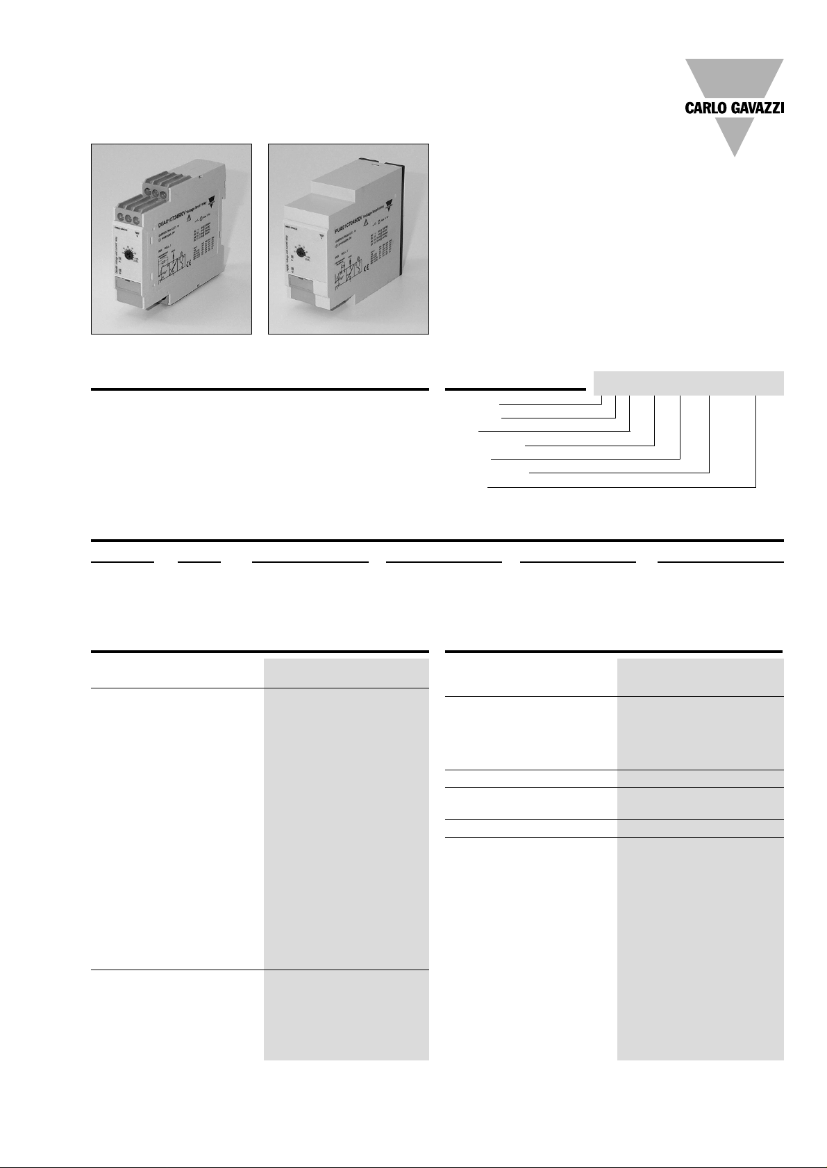
DUA01
PUA01
Mounting Output Supply: 24 VDC Supply: 48 VDC Supply: 24/48 VAC Supply: 115/230 VAC
DIN-rail SPDT DUA 01 C 724 500V DUA 01 C 748 500V DUA 01 C B48 500V DUA 01 C B23 500V
Plug-in SPDT PUA 01 C 724 500V PUA 01 C 748 500V PUA 01 C B48 500V PUA 01 C B23 500V
2 Specifications are subject to change without notice (06.11.01)
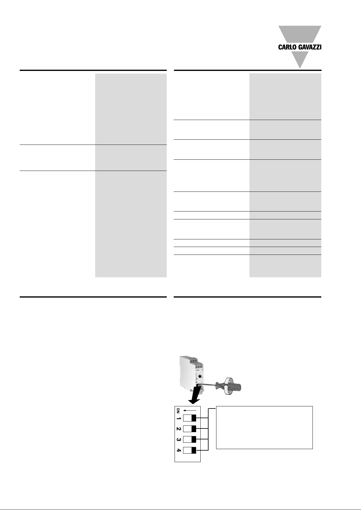
Range - Level Setting
Adjust the measuring range
setting the DIP switches 1 to
4 as shown below.
To access the DIP switches
open the grey plastic cover
using a screwdriver as
shown below.
Centre knob:
Setting of voltage on relative
scale: from 10 to 110% of the
full-scale value.
Hysteresis:
Approx. 4% of set value, it
can be extended by inserting
a resistor between terminals
Z1, Y1 or 8, 9.
Approx. resistor values:
10%: 180 kΩ
25%: 47 kΩ
50%: 22 kΩ
75%: 15 kΩ
Latch: < 500 Ω
DUA01, PUA01
Mode of Operation
DUA01 and PUA01 monitor
both AC and DC over voltage.
When connected with MI or
MP current transformer
(using the 0.4 - 4 V
p
range)
they can monitor 1-phase or
3-phase AC currents up to
500 A.
Example 1
(connection between terminals Z1, Y1 or 8, 9 - latch
function enabled)
The relay operates and latches in operating position
when the measured value
exceeds the set level. Provided that the voltage has
dropped min. 4% below the
set point (see hysteresis),
the relay releases when the
interconnection between terminals Z1, Y1 or 8, 9 is interrupted or the power supply
is interrupted as well.
Example 2 (MI CT)
(no connection between terminals Z1, Y1 or 8, 9)
The relay operates when the
current flowing through the
CT exceeds the set level. It
releases when the current
drops min. 4% below the set
level (see hysteresis) or
when power supply is interrupted.
Example 3 (MP CT)
(no connection between terminals Z1, Y1 or 8, 9 - latch
function disabled)
The relay operates when the
maximum current flowing
through the CT exceeds the
set level. It releases when
the maximum current drops
min. 4% below the set level
(see hysteresis) or when
power supply is interrupted.
Power supply
Overvoltage cat. III
Rated operational voltage (IEC 60664, IEC 60038)
through terminals:
A1, A2 or A3, A2 (DUA01)
2, 10 or 11, 10 (PUA01)
724: 24 VDC ± 20%, insulated
748: 48 VDC ± 20%, insulated
B48: 24/48 VAC ± 15%
45 to 65 Hz, insulated
B23: 115/230 VAC ± 15%
45 to 65 Hz, insulated
Dielectric voltage DC supply AC supply
Supply to input 2 kV 4 kV
Supply to output 4 kV 4 kV
Input to output 4 kV 4 kV
Rated operational power
AC 4 VA
DC 2 W
Supply Specifications
Reaction time
Alarm ON delay < 100 ms
(voltage rising from
-20% to +20% set value)
Alarm OFF delay < 300 ms
(voltage decreasing from
+20% to -20% set value)
Accuracy (15 min warm-up time)
Temperature drift ± 1000 ppm/°C
Repeatability ± 0.5% on full-scale
Indication for
Power supply ON LED, green
Output relay ON LED, red
Environment (EN 60529)
Degree of protection IP 20
Pollution degree 3 (DUA01), 2 (PUA01)
Operating temperature -20 to 60°C, R.H. < 95%
Storage temperature -30 to 80°C, R.H. < 95%
Housing dimensions
DIN-rail version 22.5 x 80 x 99.5 mm
Plug-in version 36 x 80 x 87 mm
Weight Approx. 150 g
Screw terminals
Tightening torque Max. 0.5 Nm
acc. to IEC 60947
Approvals UL, CSA (except 748)
CE Marking Yes
EMC
Electromagnetic Compatibillity
Immunity According to EN 61000-6-2
Emission According to EN 50081-1
General Specifications
Measuring range
OFF ON OFF OFF 0.4 to 4 V
p
ON OFF OFF OFF 2 to 20 VAC/DC
OFF OFF OFF OFF 5 to 50 VAC/DC
ON OFF ON OFF 20 to 200 VAC/DC
ON OFF OFF ON 50 to 500 VAC/DC
 Loading...