

Carlo Gavazzi DTA01 Catalog Page
Specifications are subject to change without notice (19.12.03) 1
Monitoring Relays
Product Description Ordering Key
Housing
Function
Type
Item number
Output
Power supply
• Motor temperature monitoring relay
• Measuring ranges: PTC according to EN 44081
• Remote and local alarm reset (DTA02, PTA02)
• Output: 8 A SPDT relay normally energized
• For mounting on DIN-rail in accordance with DIN/EN
50 022 (DTA01, DTA02) or plug-in module (PTA01,
PTA02)
• 22.5 mm Euronorm housing (DTA01, DTA02) or
36 mm plug-in module (PTA01, PTA02)
• LED indication for relay and power supply ON (DTA02,
PTA02)
• Galvanically separated power supply
Type Selection
Input (PTC) DTA01, DTA02: Terminals T1, T2
PTA01, PTA02: Terminals 5, 6
Measuring ranges
Max cold PTC resistance 1500 Ω
Alarm setpoint 3100 Ω ± 10%
Return setpoint 1650 Ω ± 10%
Short-circuit detection 0 to 10 Ω
Measurement voltage
≤2.5V (acc. to IEC 60034-11)
Contact input
DTA02 Terminals Z1, Z2
PTA02 Terminals 8, 9
Disabled > 10 kΩ
Enabled < 500 Ω
Alarm reset > 500 ms
Motor temperature
Types DTA01, PTA01, DTA02, PTA02
Input Specifications
Output SPDT or DPDT relay
Rated insulation voltage 250 VAC
Contact ratings (AgSnO2)µ
Resistive loads AC 1 8 A @ 250 VAC
DC 12 5 A @ 24 VDC
Small inductive loads AC 15 2.5 A @ 250 VAC
DC 13 2.5 A @ 24 VDC
Mechanical life ≥ 30 x 10
6
operations
Electrical life ≥ 10
5
operations
(at 8 A, 250 V, cos ϕ = 1)
Operating frequency ≤ 7200 operations/h
Dielectric strength
Dielectric voltage
≥ 2 kVAC (rms)
Rated impulse withstand volt. 4 kV (1.2/50 µs)
Output Specifications
DTA 01 C 230
DTA01, DTA02, PTA01 and
PTA02 are precise thermistor
monitoring relays.
They can be used to monitor
the temperature of the coils of
a motor with built-in PTC’s.
The alarm status of the relay
can be reset by either an
external contact or an internal
button (DTA02, PTA02).
The test button allows the
simulation of the fault condition (DTA02, PTA02).
The red LED indicates the
alarm status.
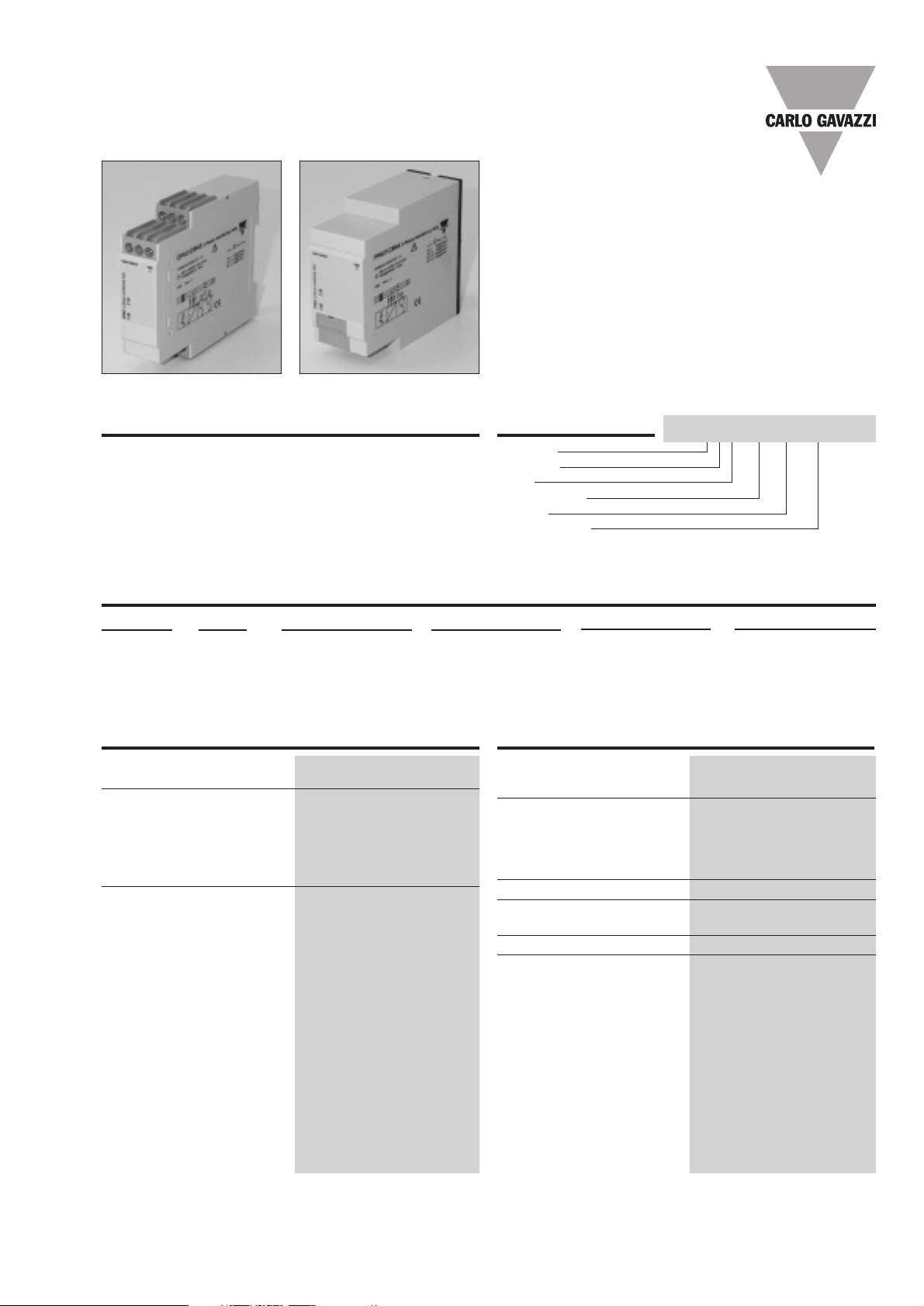
DTA01, DTA02
PTA01, PTA02
Mounting Output Supply: 24 VDC Supply: 24 VAC Supply: 115 VAC Supply: 230 VAC
DIN-rail SPDT DTA 01 C 724 DTA 01 C 024 DTA 01 C 115 DTA 01 C 230
Plug-in SPDT PTA 01 C 724 PTA 01 C 024 PTA 01 C 115 PTA 01 C 230
DIN-rail SPDT DTA 02 C 724 DTA 02 C 024 DTA 02 C 115 DTA 02 C 230
Plug-in SPDT PTA 02 C 724 PTA 02 C 024 PTA 02 C 115 PTA 02 C 230

2 Specifications are subject to change without notice (19.12.03)
DTA01, DTA02, PTA01, PTA02
Mode of Operation
DTA01, DTA02, PTA01 and
PTA02 monitor the resistance value of the PTC
resistors connected to the
terminals T1 and T2 (or 5
and 6). This value is related
with their temperature (often
the three coils of a motor) so
to offer a prompt reaction to
over temperature.
Example 1 - DTA01 or PTA01
The relay operates as long
as the measured resistance
is below the rated value. The
relay releases if the measured resistance (i.e. the
temperature of the motor
coils) exceeds the rated value.
Example 2 - DTA02 or PTA02
The relay operates and the
yellow LED is ON as long as
the measured resistance is
below the rated value. The
relay releases and the yellow
LED is OFF if the measured
resistance (i.e. the temperature of the motor coils)
exceeds the rated value.
Provided that the resistance
has dropped below the rated value (i.e. the temperature of the motor coils has
returned cold), the relay
operates when the interconnection between terminals
Z1, Z2 or 8, 9 is interrupted
or the reset button on the
front of the unit is pressed.
Power supply
Overvoltage cat. III
Rated operational voltage (IEC 60664, IEC 60038)
through terminals:
A1, A2 (DTA01, DTA02)
2, 10 (PTA01, PTA02)
724: 24 VDC ± 20%, insulated
024: 24 VAC ± 15%
45 to 65 Hz, insulated
115: 115 VAC ± 15%
45 to 65 Hz, insulated
230: 230 VAC ± 15%
45 to 65 Hz, insulated
Dielectric voltage
(1.2/50 µs)
DC supply AC supply
Supply to input 2 kV 4 kV
Supply to output 4 kV 4 kV
Input to output 4 kV 4 kV
Rated operational power
AC 2.5VA
DC 1.5W
Supply Specifications
Reaction time
Alarm ON delay < 150 ms
(resistance rising from
-20% to +20% set value)
Reset delay < 500 ms
(resistance decreasing from
+20% to -20% set value)
Accuracy (15 min warm-up time)
Temperature drift ± 1000 ppm/°C
Repeatability ± 0.5% on full-scale
Indication for
Power supply ON LED, green
Relay ON LED, yellow
Environment (EN 60529)
Degree of protection IP 20
Pollution degree 3 (DTA01, DTA02),
2 (PTA01, PTA02)
Operating temperature -20 to 60°C, R.H. < 95%
Storage temperature -30 to 80°C, R.H. < 95%
Housing dimensions
DIN-rail version 22.5 x 80 x 99.5 mm
Plug-in version 36 x 80 x 87 mm
Weight Approx. 150g
Screw terminals
Tightening torque Max. 0.5 Nm
acc. to IEC 60947
Approvals UL, CSA
CE Marking Ye s
EMC
Electromagnetic Compatibillity
Immunity According to EN 61000-6-2
Emission According to EN 50081-1
General Specifications
 Loading...