

Page 1
Installation, Operation, and Maintenance Instructions
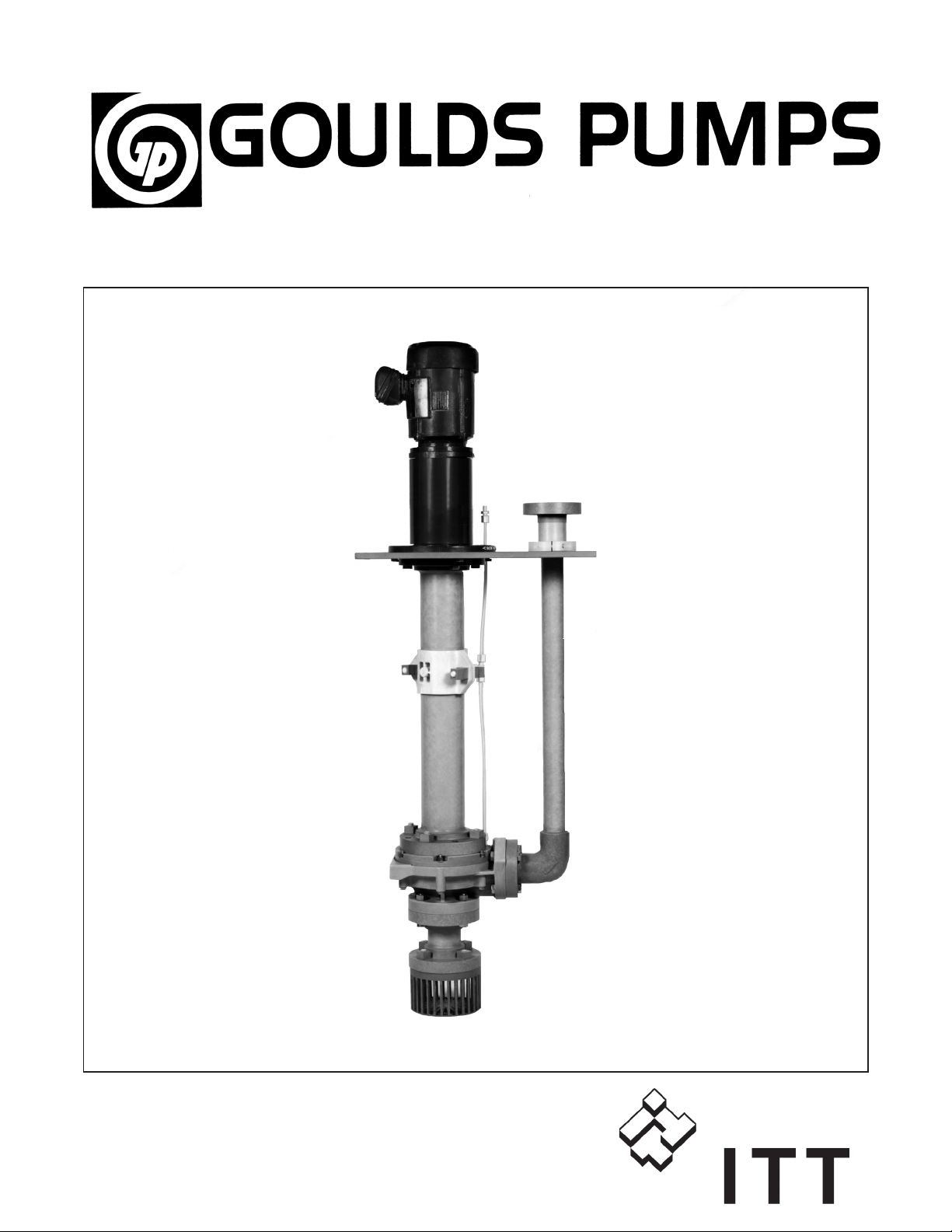
Model 4550
Page 2

4 4550 IOM 5/08
Page 3

FOREWORD
This manual provides instructions for the Installation, Operation, and Maintenance of the ITT Goulds
Model 4550 Non-Metallic Vertical Process Pump. This manual covers the standard product plus
common options that are available. For special options, supplemental instructions are supplied. This
manual must be read and understood before installation and start-up.
The design, materials, and workmanship incorporated in the construction of ITT Goulds pumps makes
them capable of giving long, trouble-free service. The life and satisfactory service of any mechanical
unit, however, is enhanced and extended by correct application, proper installation, periodic inspection,
condition monitoring, and careful maintenance. This instruction manual was prepared to assist operators
in understanding the construction and the correct methods of installing, operating, and maintaining these
pumps.
ITT Goulds shall not be liable for physical injury, damage, or delays caused by a failure to
observe the instructions for installation, operation, and maintenance contained in this manual.
Warranty is valid only when genuine ITT Goulds parts are used.
Use of the equipment on a service other than stated in the order will nullify the warranty, unless written
approval is obtained in advance from ITT Goulds Pumps.
Supervision by an authorized ITT Goulds' representative is recommended to assure proper installation.
Additional manuals can be obtained by contacting your local ITT Goulds representative or by calling
1-800-446-8537.
THIS MANUAL EXPLAINS
n
Proper Installation
n
Start-up Procedures
n
Operation Procedures
n
Routine Maintenance
n
Pump Overhaul
n
Troubleshooting
n
Ordering Spare or Repair Parts
4550 IOM 5/08 5
Page 4

6 4550 IOM 5/08
Page 5

TABLE OF CONTENTS
PAGE SECTION
9 SAFETY 1
11 GENERAL INFORMATION 2
13 INSTALLATION 3
17 OPERATION 4
21 PREVENTIVE MAINTENANCE 5
23 DISASSEMBLY & REASSEMBLY 6
1
29 ORDERING SPARE PARTS 7
31 APPENDIX 8
4550 IOM 5/08 7
Page 6

8 4550 IOM 5/08
Page 7

IMPORTANT SAFETY NOTICE
To: Our Valued Customers
User safety is a major focus in the design of our products. Following the precautions outlined in this
manual will minimize your risk of injury.
ITT Goulds pumps will provide safe, trouble-free service when properly installed, maintained, and
operated.
Safe installation, operation, and maintenance of ITT Goulds Pumps equipment are an essential end user
responsibility. This Pump Safety Manual identifies specific safety risks that must be considered at all
times during product life. Understanding and adhering to these safety warnings is mandatory to ensure
personnel, property, and/or the environment will not be harmed. Adherence to these warnings alone,
however, is not sufficient — it is anticipated that the end user will also comply with industry and corporate
safety standards. Identifying and eliminating unsafe installation, operating and maintenance practices is
the responsibility of all individuals involved in the installation, operation, and maintenance of industrial
equipment.
Please take the time to review and understand the safe installation, operation, and maintenance guidelines
outlined in this Pump Safety Manual and the Instruction, Operation, and Maintenance (IOM) manual.
Current manuals are available at
your nearest Goulds Pumps sales representative.
www.gouldspumps.com/literature_ioms.html or by contacting
These manuals must be read and understood before installation and star t-up.
For additional information, contact your nearest Goulds Pumps sales representative or visit our Web site at
www.gouldspumps.com.
S-1
Page 8
SAFETY WARNINGS
Specific to pumping equipment, significant risks bear reinforcement above and beyond normal safety precautions.
WARNING
A pump is a pressure vessel with rotating parts that can be hazard o us. An y press ure vessel can explode,
rupture, or discharge its contents if sufficiently ove r press u r i zed causi n g deat h, personal injury, property
damage, and/or damage to the environment. All necessary measures must be taken to ensure over
pressurization does not occur.
WARNING
Operation of any pumping system with a blocked suction and discharge must be avoided in all cases.
Operation, even for a brief period under these conditions, can cause superheating of enclosed pumpage and
result in a violent explosion. All necessary measures must be taken by the end user to ensure this condition is
avoided.
WARNING
The pump may handle hazardous and/or toxic fluids. Care must be taken to identify the contents of the pump
and eliminate the possibility of exposure, particularly if hazardous and/or toxic. Potential hazards include, but
are not limited to, high temperature, flammable, acidic, caustic, explosive, and other risks.
WARNING
Pumping equipment Instruction, Operation, and Maintenance manuals clearly identify accepted methods for
disassembling pumping units. These methods must be adhered to. Specifically, applying heat to impellers
and/or impeller retaining devices to aid in their removal is strictly forbidden. Trapped liquid can rapidly
expand and result in a violent explosion and injury.
ITT Goulds Pumps will not accept responsibility for physical injury, damage, or delays caused by a failure to
observe the instructions for installation, operation, and maintenance contained in this Pump Safety Manual or the
current IOM available at www.gouldspumps.com/literature.
S-2
Page 9
SAFETY
DEFINITIONS
Throughout this manual the words WARNING, CAUTION, ELECTRICAL, and ATEX are used to indicate
where special operator attention is required.
Observe all Cautions and Warnings highlighted in this Pump Safety Manual and the IOM provided with
your equipment.
WARNING
Indicates a hazardous situation which, if not avoided, could result in death or serious injury.
Example:
Pump shall never be operated without coupling guard installed correctly.
CAUTION
Indicates a hazardous situation which, if not avoi ded, could result in minor or moderate injury.
Example: Throttling flow from the suction side may cause cavitation and pump damage.
ELECTRICAL HAZARD
Indicates the possibility of electrical risks if directions are not followed.
Example: Lock out driver power to prevent electric shock, accidental start-up, and physical injury.
When installed in potentially explosive atmospheres, the instructions that follow the Ex symbol must be
followed. Personal injury and/or equipment damage may occur if these instructions are not followed. If there
is any question regarding these requirements or if the equipment is to be modified, please contact an ITT
Goulds Pumps representative before proceeding.
Example:
parts, resulting in a spark and heat generation.
Improper impeller adjustment could cause contact between the rotating and stationary
S-3
Page 10

GENERAL PRECAUTIONS
WARNING
A pump is a pressure vessel with rotating parts that can be hazardous. Hazardous fluids may be contained by the
pump including high temperature, flammable, acidic, caustic, explosive, and other risks. Operators and
maintenance personnel must realize this and follow safety measures. Personal injuries will result if procedures
outlined in this manual are not followed. ITT Goulds Pumps will not accept responsibility for physical injury,
damage or delays caused by a failure to observe the instructions in this manual and the IOM provided with your
equipment.
WARNING
WARNING
General Precautions
NEVER use heat to disassemble pump due to risk of explosion from tapped liquid.
NEVER APPLY HEAT TO REMOVE IMPELLER. It may explode due to
trapped liquid.
WARNING
WARNING
WARNING
WARNING
WARNING
WARNING
WARNING
WARNING
WARNING
NEVER operate pump without safety devices installed.
NEVER operate pump without coupling guard correctly installed.
NEVER run pump below recommended minimum flow when dry, or without
prime.
ALWAYS lock out power to the driver befo re per fo rming pump maintenance.
NEVER operate pump with discharge valve closed.
NEVER operate pump with suction valve closed.
DO NOT change service application without approval of an authorized ITT
Goulds Pumps representative.
Safety Apparel:
Insulated work gloves when handling hot bearings or using bearing heater
Heavy work gloves when handling parts with shar p ed ges, especially
impellers
Safety glasses (with side shields) for eye protection
Steel-toed shoes for foot protection when handling parts, heavy tools, etc.
Other personal protective equipment to protect against hazardous/toxic fluids
Receiving:
Assembled pumping units and their components are heavy. Failure to properly lift
and support equipment can result in serious physical injury and/or equipment
damage. Lift equipment only at specifically identified lifting points or as
instructed in the current IOM. Current manuals are available at
www.gouldspumps.com/literature_ioms.html or from your local ITT Goulds
Pumps sales representative. Note: Lifting devices (eyebolts, slings, spreaders, etc.)
must be rated, selected, and used for the entire load being lifted.
Alignment:
WARNING
Shaft alignment procedures must be followed to prevent catastrophic failure of
drive components or unintended contact of rotating parts. Follow coupling
manufacturer’s coupling installation and operation procedures.
S-4
Page 11

WARNING
CAUTION
General Precautions
Before beginning any alignment procedure, make sure driver power is locked out.
Failure to lock out driver power will result in serious physical injury.
Piping:
Never draw piping into place by forcing at the flan ged con necti on s of t he pump.
This may impose dangerous strains on the unit and cause misalignment between
pump and driver. Pipe strain will adversely effect the operation of the pump
resulting in physical injury and damage to the equipment.
WARNING
WARNING
WARNING
WARNING
WARNING
WARNING
WARNING
WARNING
WARNING
WARNING
WARNING
CAUTION
CAUTION
WARNING
Flanged Connections:
Use only fasteners of the proper size and material.
Replace all corroded fasteners.
Ensure all fasteners are properly tightened and there are no missing fasteners.
Startup and Operation:
When installing in a potentially explosive environment, please ensure that the
motor is properly certified.
Operating pump in reverse rotation may result in contact of metal parts, heat
generation, and breach of containment.
Lock out driver power to prevent accidental start-up and physical injury.
The impeller clearance setting procedure must be followed. Improperly setting
the clearance or not following any of the proper procedures can result in sparks,
unexpected heat generation and equipment damage.
If using a cartridge mechanical seal, the centering clips must be installed and set
screws loosened prior to setting impeller clearance. Failure to do so could result
in sparks, heat generation, and mechanical seal damage.
The coupling used in an ATEX classified environment must be properly certified
and must be constructed from a non-sparking material.
Never operate a pump without coupling guard properly installed. Personal injury
will occur if pump is run without coupling guard.
Make sure to properly lubricate the bearings. Failure to do so may result in excess
heat generation, sparks, and / or premature failure.
The mechanical seal used in an ATEX classified environment must be properly
certified. Prior to start up, ensure all points of potential leakage of process fluid to
the work environment are closed.
Never operate the pump without liquid supplied to mechanical seal. Running a
mechanical seal dry, even for a few seconds, can cause seal damage and must be
avoided. Physical injury can occur if mechanical seal fails.
Never attempt to replace packing until the driver is properly locked out and the
coupling spacer is removed.
WARNING
WARNING
S-5
Dynamic seals are not allowed in an ATEX classified environment.
DO NOT operate pump below minimum rated flows or with suction and/or
discharge valve closed. These conditions may create an explosive hazard due to
vaporization of pumpage and can quickly lead to pump failure and physical injury.
Page 12

WARNING
WARNING
WARNING
WARNING
WARNING
CAUTION
CAUTION
WARNING
CAUTION
CAUTION
General Precautions
Ensure pump is isolated from system and pressure is relieved before
disassembling pump, removing plu gs, ope ni n g vent or drain valves, or
disconnecting piping.
Shutdown, Disassembly, and Reassembly:
Pump components can be heavy. Proper methods of lifting must be employed to
avoid physical injury and/or equipment damage. Steel toed shoes must be worn at
all times.
The pump may handle hazardous and/or toxic fluids. Observe proper
decontamination procedures. Proper personal protective equipment should be
worn. Precautions must be taken to prevent physical injury. Pumpage must be
handled and disposed of in conformance with applicable environmental
regulations.
Operator must be aware of pumpage and safety precautions to prevent physical
injury.
Lock out driver power to prevent accidental startup and physical injury.
Allow all system and pump components to cool before handling them to prevent
physical injury.
If pump is a Model NM3171, NM3196, 3198, 3298, V3298, SP3298, 4150, 4550,
or 3107, there may be a risk of static electric discharge from plastic parts that are
not properly grounded. If pumped fluid is non-conductive, pump should be
drained and flushed with a conductive fluid under conditions that will not allow
for a spark to be released to the atmosphere.
Never apply heat to remove an impeller. The use of heat may cause an explosion
due to trapped fluid, resulting in severe physical injury and property damage.
Wear heavy work gloves when handling impellers as sharp edges may cause
physical injury.
Wear insulated gloves when using a bearing heater. Bearings will get hot and can
cause physical injury.
S-6
Page 13

ATEX CONSIDERATIONS and INTENDED USE
Special care must be taken in potentially explosive environments to ensure that the equipment is properly
maintained. This includes but is not limited to:
1. Monitoring the pump frame and liquid end temperature.
2. Maintaining proper bearing lubrication.
3. Ensuring that the pump is operated in the intended hydraulic range.
The ATEX conformance is only applicable when the pump unit is operated within its intended use. Operating,
installing or maintaining the pump unit in any way that is not covered in the Instruction, Operation, and
Maintenance manual (IOM) can cause serious personal injury or damage to the equipment. This includes any
modification to the equipment or use of parts not provided by ITT Goulds Pumps. If there is any question
regarding the intended use of the equipment, please contact an ITT Goulds represe ntative before proceeding.
Current IOMs are available at
Pumps Sales representative.
All pumping unit (pump, seal, coupling, motor and pump accessories) certified for use in an ATEX classified
environment, are identified by an ATEX tag secured to the pump or the baseplate on which it is mounted. A
typical tag would look like this:
www.gouldspumps.com/literature_ioms.html or from your local ITT Goulds
The CE and the Ex designate the ATEX compliance. The code directly below these symbols reads as follows:
II = Group 2
2 = Category 2
G/D = Gas and Dust present
T4 = Temperature class, can be T1 to T6 (see Table 1)
Table 1
Max permissible
surface temperature
Code
T1 842 (450) 700 (372)
T2 572 (300) 530 (277)
T3 392 (200) 350 (177)
T4 275 (135) 235 (113)
T5 212 (100) Option not available
T6 185 (85) Option not available
o
F (oC)
The code classification marked on the equipment must be in accordance with the specified area where the
equipment will be installed. If it is not, do not operate the equipment and contact your ITT Goulds Pumps sales
representative before proceeding.
Max permissible
liquid temperature
o
F (oC)
S-7
Page 14

PARTS
The use of genuine Goulds parts will provide the safest and
most reliable operation of your pump. ITT Goulds Pumps ISO
certification and quality control procedures ensure the parts are
manufactured to the highest quality and safety levels.
Please contact your local Goulds representative for details on
genuine Goulds parts.
S-8
Page 15

GENERAL INFORMATION
PUMP DESCRIPTION .................................11
GENERAL INFORMATION .............................11
Importance of Instructions ...................................... 11
Precautions .............................................. 11
Special Warnings ........................................... 12
Receiving Inspection - Shortages................................... 12
Preservation and Storage ....................................... 12
Handling Techniques ......................................... 12
PUMP DESCRIPTION
3
ITT Goulds Model 4550 pumps are centrifugal wet pit
type pumping units for installation in a pit or a tank
vented to atmospheric pressure. All pump parts in contact
with the fluid are constructed of glass reinforced vinyl
ester (VR-1) or epoxy (EY-1) resin with the exception of
the shaft and hardware, which are of an alloy selected for
GENERAL INFORMATION
IMPORTANCE OF INSTRUCTIONS
This instruction manual is intended to assist those
involved with the installation, operation and maintenance
of ITT Goulds Model 4550 pump. It is recommended that
this manual be thoroughly reviewed prior to installing or
performing any work on the pump or motor.
Study thoroughly and carefully follow the instructions for
installation and operation. Keep this instruction manual
available for reference.
Further information may be obtained by contacting the
Seneca Falls Operations at ITT Goulds Pumps, Seneca
Falls, N.Y. 13148, or your nearest ITT Goulds sales
office or representative.
compatibility with the fluid pumped. Vertical pumps
contain one or more nonmetallic line bearings which
require a source of fluid flush to lubricate and cool the
bearings. Cantilever pumps are of the overhung shaft type
and do not contain any bearings below the mounting
plate.
2. Never rotate pump in the wrong direction. Severe
pump damage can be caused by wrong rotation.
Proper rotation direction is indicated on the motor
support (240).
3. Never force pump parts during disassembly or
assembly.
4. Avoid undue impacts or shocks to pump while
hanging.
5. Do not put pipe strain or bending moments on
discharge pipe and flange (195). Piping should be
independently supported and should line up naturally
with the discharge. Use properly restrained expansion
joints between pump and piping.
PRECAUTIONS
s
! WARNING
Personal injuries will result if procedures outlined
in this manual are not followed.
1. Do not over tighten bolts and nuts. Tighten according
to chart in Appendix I.
4550 IOM 5/08 11
6. Clean liquid must be applied to the column bearings
(213) at a rate of 0.25 - 0.50 GPM (0.16 - 0.32 I/s)
7. Never operate pump without coupling guard correctly
installed.
8. Never operate pump beyond the rated conditions to
which the pump was supplied.
9. Never operate pump without safety devices installed.
Page 16

10. Lower ends of pumps must be braced in turbulent
sumps.
11. Always lock out power to the driver before
performing pump maintenance.
SPECIAL WARNINGS
PRESERVATION AND STORAGE
ITT Goulds' normal domestic storage preparation is
suitable for protecting the pump during shipment in
covered trucks. It also provides protection during covered
storage at the job site and for a short period before
installation and start-up.
ITT Goulds Pumps will not be liable for any damages or
delay caused by failure to comply with the provisions of
this instruction manual.
This pump is not to be operated at speeds, working
pressures, discharge pressures or temperatures higher
than, or used with liquids other than, that stated in
original order acknowledgement without written
permission of ITT Goulds Pumps.
RECEIVING INSPECTION SHORTAGES
Care should be taken when unloading pumps. If shipment
is not delivered in good order and in accordance with the
bill of lading, note the damages or shortages on both
receipt and freight bill. Make any claims to the
transportation company promptly.
Instruction sheets on various components, as well as the
installation, operation and maintenance instructions for
the pump, are included in the shipment.
Do not discard!
Motor manufacturers should be contacted for their
recommendations on preservation and protection
procedures.
HANDLING TECHNIQUES
! WARNING
s
Pump and components are heavy. Failure to
properly lift and support equipment could result in
serious physical injury, or damage to pumps. Steel
toed shoes must be worn at all times.
Care should be used in moving pumps. Slings should be
put under the mounting plate (189) to properly support
the unit.
The best method of lifting unit is with parallel straps
attached to a horizontal bar.
12 4550 IOM 5/08
Page 17

INSTALLATION
LOCATION OF UNIT .................................13
PREPARATION FOR INSTALLATION .......................13
INSTALLATION OF UNIT IN PIT ..........................13
Assembly of Motor to Motor Support ................................ 14
Rotation Check ............................................ 14
Connection of Piping ......................................... 14
Alignment of Flexible Coupling ................................... 14
Impeller Adjustment - All Models .................................. 14
LOCATION OF UNIT
Vertical sump pumps are to be mounted directly in a
sump or tank, with proper support under the polyester
mounting plate (189). Floor space and head room allotted
to the unit must be sufficient for removal from the sump
or tank.
PREPARATION FOR INSTALLATION
3
Vertical units are shipped completely assembled except
for level controls and motors. Make sure all bolts are
securely tightened. Use a torque wrench on all
non-metallic joints. Bolt and nut torque values should not
exceed those shown in the chart in Appendix I.
INSTALLATION OF UNIT IN PIT
1. Inspect pump and any accessories packed with the
unit to assure no damage has occurred during transit.
NOTE: Motors are shipped separately and should
also be inspected.
Install the pump assembly in the pit before mounting
the motor to prevent damage.
$
When handling the pump unit, it is very important
to pick up the unit by the top to prevent damage to
the pump.
2. A rope or sling should be attached to the bearing
pedestal (108) or the mounting plate (189). Serious
damage may result if the unit is picked up by the
column shaft (192) or discharge pipe (195). The
CAUTION
Install level controls per the manufacturer's
recommendations included with the controls.
pump assembly must be lowered carefully into the
pit. Care must be taken to guide the pump as it is
lowered into the pit to avoid striking the sides.
3. When the mounting plate (189) is resting in the
proper position, check the level of the plate, and shim
if necessary to level the unit. The pump shaft must be
vertical to avoid a bending stress on the shaft column,
and to avoid bearing damage during operation. Check
the shaft column (192) with a level to be sure the unit
is straight and plumb.
4. Bolt down the mounting plate, and be sure it is
supported on all four sides.
NOTE: There should be a minimum of 4 to 12
inches between the bottom of the suction strainer
and the bottom of the tank of pit.
For higher flow pumps, this clearance may be
specified as greater; check your outline drawing.
4550 IOM 5/08 13
Page 18

5. Be sure the source of lubrication to the line bearings
on 4550 Series vertical pumps has been connected if
an external flush source is required. Check all fittings
at the line bearings to be sure no damage has
occurred during shipment.
6. Connect level control, if the pump is so equipped.
ASSEMBLY OF MOTOR TO MOTOR
SUPPORT
If motor is shipped from ITT Goulds' factory, both
coupling halves will be assembled on shafts in their
correct positions. If motor is shipped direct or furnished
by customer, the motor half coupling must be fitted on
motor shaft.
Place motor on motor support (240) and tighten hex cap
screws snugly.
ROTATION CHECK
Before coupling is connected, motor should be wired and
the direction of rotation checked. A rotation arrow is
located on the motor support (240).
IMPELLER ADJUSTMENT - ALL
MODELS
NOTE: All models are preadjusted before leaving
the factory. Check to see if shaft turns freely by
hand. If no binding is noted, no further adjustment
is needed. If binding is noted, follow adjustment
procedure below.
! WARNING
s
Never adjust impeller with coupling connected.
The impeller must be adjusted with the pump mounted in
the vertical position.
Impeller Adjustment for 4550 Series Vertical Sizes
1x1.5-6 3x4-8
1.5x3-6 1.5x3-10
2x3-6 2x3-10
1x1.5-8 3x4-10
1.5x3-8 4x4-10
2x3-8
Standard rotation for Model 4550 is clockwise (CW) as
viewed from the driver.
s! CAUTION
Serious damage may result if pump is run in the
wrong direction.
CONNECTION OF PIPING
Connect discharge piping to discharge pipe flange (195)
above mounting plate (189). This piping should be
independently supported, should align naturally with the
discharge flange, should be as direct as possible, and
should have a minimum number of fittings. A gate valve
should be used for flow control. There should be no strain
on the piping, and a properly restrained expansion joint
must be used.
s
! WARNING
Never draw piping into place by forcing at the
flange connections of the pump. This may impose
dangerous strains on the unit and adversely affect
the operation of the pump resulting in physical
injury and damage to the equipment.
ALIGNMENT OF FLEXIBLE
COUPLING
Check for coupling alignment by laying a straight edge
across both coupling rims at four points 90 degrees apart.
When the straight edge rests evenly at all four points, the
coupling will be in correct alignment. Tighten hex cap
screws (370U).
1. Loosen bearing cap set screw.
2. Loosen clamping screw in adjusting collar (283A).
3. Slowly rotate adjusting collar counterclock-wise
while pushing down on shaft, and rotate shaft until
you feel the impeller touch the casing face.
4. Place a dial indicator on the end of the shaft. Rotate
the collar clockwise (CW), raising the shaft to the
clearance specified in Table 1.
NOTE: For “Quick Field” adjustment, rotate the
collar 90° clockwise, while securing the shaft.
5. Re-lock adjusting collar clamping screw (283A).
6. Tighten set screw.
7. Rotate shaft by hand to insure that there is no binding
or rubbing of parts.
Table 1
Impeller Diameter
(Inches)
Up to 8" .015
8" to 10" .020
10" to 15" .025
Clearance
(Inches)
14 4550 IOM 5/08
Page 19

Impeller Adjustment for Vertical Sizes:
4x6-10 6x8-13
2x3-13 8x10-15
3x4-13 10x12-16
4x6-13 All Cantilever Sizes
1. Loosen three adjusting screws evenly.
2. Tighten up equally on outer screw until you can feel
the impeller just starting to rub on the casing face.
Rotate the shaft frequently while taking up on these
bolts, so you know when it begins to bind.
3. Now loosen the outer screw evenly until you can
insert a feeler gauge, corresponding to the impeller
clearance from Table 1 above, under each of the three
bolt heads.
NOTE: For “Quick Field” adjustment, loosen outer
screw two flats.
4. Tighten adjusting screw evenly until the bearing
housing is backed up against the outer screw.
5. Check to be sure the shaft turns freely.
4
4550 IOM 5/08 15
Page 20

16 4550 IOM 5/08
Page 21

OPERATION
PREPARATION FOR OPERATION .........................17
Motor Assembly ............................................ 17
Motor Bearings ............................................ 17
Rotation Check ............................................ 17
Pump Bearings ............................................ 17
Piping the Pump............................................ 17
Coupling ................................................ 18
Check For Free Turning ....................................... 18
Priming ................................................ 18
OPERATION ......................................18
Start-Up Procedure .......................................... 18
Starting the Pump........................................... 19
Operational Checks .......................................... 19
Operating with Surge Conditions In Line .............................. 19
Freezing Conditions.......................................... 19
Shutdown Practice .......................................... 19
4
PREPARATION FOR OPERATION
MOTOR ASSEMBLY
When the motor is furnished by the customer, the motor
coupling half must be installed. Place motor on motor
support, start the mounting bolts into the motor, and
securely tighten the motor mounting bolts.
MOTOR BEARINGS
Check and follow motor manufacturer's lubrication
instructions.
ROTATION CHECK
Before coupling sleeve is connected, the motor should be
wired and the direction of rotation checked. The motor
should be rotating in a clockwise (CW) direction when
looking down on top of the motor.
s
! WARNING
Serious damage could occur if pump is operated in
the wrong direction.
After the proper motor rotation direction is established,
loosen the motor coupling half and install the coupling
sleeve. Adjust the motor coupling half and tighten. Rotate
the coupling to insure no binding occurs and install the
coupling guard. Proper alignment of the pump and motor
is of extreme importance for trouble free mechanical
operation. Check the coupling alignment by laying a
straight-edge across both coupling hubs at four points, 90
degrees apart.
PIPING THE PUMP
The pump discharge pipe is connected to the process
piping above the mounting plate. The piping should be as
direct as possible with a minimum number of fittings. It is
recommended that a check valve be installed in the pump
discharge line as close as possible to where the discharge
pipe comes through the mounting plate. This will prevent
backflow from the discharge line upon pump shutdown
and reverse rotation of the pump shaft, which could cause
serious pump damage. This is particularly critical when
the pump is on level control operation with frequent
start/stop cycles.
NOTE: It is also highly recommended for long
pump life that properly anchored bellows type
expansion joints be installed at the discharge flange
connection. See Figure 1 in Disassembly Section
for typical installations.
4550 IOM 5/08 17
Page 22

COUPLING
Assure that the coupling is properly lubricated if required
by the coupling manufacturer's instructions.
CHECK FOR FREE TURNING
Before pump is started, rotate shaft by hand to be sure it is
free. If pump cannot be turned by hand, or binding or
rubbing is noticed, refer to Installation of Unit in Pit.
Install coupling guard securely before starting the pump
to prevent serious injury.
PRIMING
The pump must be full of liquid with specified
submergence head above centerline of impeller.
PUMP BEARINGS
Pump Bearings - Vertical 4550 Series
1. Upper Ball Type (Pedestal)
All vertical pumps have one ball type thrust bearing
(112) located above the mounting plate. With the
exception of sizes 4x6-10, 2x3-13, 3x4-13, 4x6-13,
6x8-13 and 8x10-15, the bearings are permanently
lubricated sealed bearings, and require no further
lubrication. To lubricate the bearing, shut off the
pump and remove the coupling guard. Remove the
grease vent plug opposite the grease fitting. Inject
grease through the fitting until it appears at the
opposite vent hole. Reinstall the coupling guard and
run the pump until it reaches operating temperature
(approximately 1-2 hours). This will allow excess
grease to purge from the bearing cavity. Shut off the
pump and reinstall the grease vent plug.
2. Lower Sleeve Type
4550 Series vertical pumps have one or more sleeve
type line shaft bearings (197B). The bearings are
nonmetallic and are self-lubricating, but must have
continuous clean liquid injected to flush the bearing
surface to clean and cool the bearing. The various
methods of flushing the bearing (s) are described as
follows:
External Clean Flush - In this arrangement the pump
unit is provided with flush tubing to all the line
bearings through the mounting plate where a
connection is provided for a continuous source of
clean liquid at a rate of 1/4 to 1/2 gpm per bearing
at 10-20 psi. This is the most desirable method of
bearing flush and will offer the greatest bearing life.
From the Pump Discharge - Bearings may be flushed
in this manner when the pumped fluid is clean and
free of solids. The flush tubing can be connected to
the discharge pipe to provide the lubricating and
cooling.
Cyclone Separator - When it is impossible to use an
external clean flush and the pumped fluid is not
clean, a cyclone separator may be used. The flush
tubing is run from the pump discharge to the cyclone
separator mounted on top of the mounting plate. The
clean fluid out of the separator is run to the line
bearings, and solids are returned back into the sump.
This method will prolong bearing life, but eventual
clogging of bearings must be expected, due to solid
buildup. Clean external flush is the best bearing flush
method.
$
Regardless of the method of bearing flush, the flush
system must be checked periodically to insure fluid
is being supplied to all the line bearings to prevent
damage to the pump.
CAUTION
OPERATION
s
! WARNING
Check motor rotation before coupling motor to
pump. Refer to Rotation Check for instructions.
$
Serious damage may result if pump is run in the
wrong rotation.
CAUTION
18 4550 IOM 5/08
START-UP PROCEDURE
Before the pump is started, turn pump by hand at the
coupling to insure it is free and does not rub or bind, and
reinstall the coupling guard. Turn on the flush to the
steady bearings if provided from an external source.
Inspect the pump casing to be sure it is submerged before
engaging the motor.
Page 23

$
DO NOT operate pump at reduced capacity or with
discharge valve closed. At this point, all energy
developed by the pump will convert to heat, which
may cause either mechanical damage, or vaporizing
of pump liquid in the impeller eye, causing
cavitation.
$
DO NOT operate pump when tank level drops below
minimum pump submergence.
$
DO NOT operate pump if surging occurs.
$
DO NOT operate pump if motor overloads. This will
cause overheating of the motor and possible motor
damage.
CAUTION
CAUTION
CAUTION
CAUTION
STARTING THE PUMP
! WARNING
s
Do not run pump at greatly reduced flow because
all the motor power will go into heating the liquid in
the pump and damage may result. If this condition
exists over a long period, the temperature of the
liquid in the pump may increase until the boiling
point is reached. If this occurs, the rotating parts
are exposed to vapor with no lubrication, and they
may score or even seize to the stationary parts.
Continued operation under these conditions may
create an explosive hazard due to the confined
vapor under high pressure and temperature.
OPERATING WITH SURGE
CONDITIONS IN LINE
$
If the pump is installed with a quick-acting valve in
the discharge line that could close when the pump is
running, dangerous pressure surges may be built up
that can cause damage to the pump or line. In
services of this kind, some cushioning arrangement
must be provided to protect the pumping equipment.
CAUTION
5
1. Connect coupling, following instructions for the
particular make of coupling used. This data is
supplied separately, giving complete instructions for
connection, lubrication, alignment and maintenance.
2. Check for free turning.
3. Install coupling guard.
s
! WARNING
Never operate a pump without coupling guard
properly installed. Personal injury will occur if
pump is run without coupling guard.
4. Before pump is started, the flushing flow specified in
Pump Bearings should be started. Do not run the
pump without flush to the column bearings (197B).
(Internal for clean liquids - external for dirty liquid).
5. Starting: Pump is now ready to start. Start pump with
closed or slightly opened discharge valve. Open
immediately after starting.
OPERATIONAL CHECKS
Inspect pump carefully and frequently during the first few
hours of operation. Check motor for excessive heating.
Check motor for excessive vibration or unusual noise.
FREEZING CONDITIONS
If exposed to freezing conditions while the pump is
standing idle, liquid inside the pump must be drained.
SHUTDOWN PRACTICE
When a check valve is installed in the discharge, the
pump can be shut off without closing any valves. When
no check valve is used, the discharge valve must be
closed before the pump is stopped to prevent back flow
through the pump.
s
! WARNING
When handling hazardous and/or toxic fluids,
proper personal protective equipment should be
worn. If pump is being drained, precautions must
be taken to prevent physical injury. Pumpage must
be handled and disposed of in conformace with
applicable environmental regulation.
4550 IOM 5/08 19
Page 24

20 4550 IOM 5/08
Page 25

PREVENTIVE MAINTENANCE
GENERAL COMMENTS ...............................21
Lubrication .............................................. 21
Maintenance .............................................. 21
Vibration................................................ 21
GENERAL COMMENTS
LUBRICATION
The ball bearing (112) supplied is greased for life. No
further lubrication is required. Column bearings (197B)
must be lubricated by an integral pumpage flush or clean
source of external liquid flush. Consult ITT Goulds
Pumps for appropriate option. Follow motor and
coupling manufacturers lubrication instructions.
MAINTENANCE
1. Periodically lubricate the upper ball bearing(s) when
equipped with grease fittings.
2. Check for noise (mechanical or hydraulic) and
vibration.
3. Check float switch operation.
4. Check flush line to the line shaft bearings for
buildup.
5. Check discharge pressure gauge periodically.
VIBRATION
It is good practice to periodically monitor vibration of the
pump. Normally, vibration level will be well below
accepted standards. Of equal importance is that the
vibration level not increase. If a problem with vibration is
encountered, refer to Troubleshooting in the Disassembly
& Reassembly Section.
6
4550 IOM 5/08 21
Page 26

22 4550 IOM 5/08
Page 27

DISASSEMBLY & REASSEMBLY
DISASSEMBLY.....................................23
Disassembly - Vertical 4550 Series .................................. 23
Inspection And Parts Replacement Guidelines ........................... 23
REASSEMBLY .....................................24
Troubleshooting ............................................ 25
Cross Sectional ............................................ 26
Materials of Construction ...................................... 27
Typical Vertical Pump Installations ................................. 28
DISASSEMBLY
! WARNING
s
Lockout driver power ro prevent accidental start up
and physical injury.
! WARNING
s
Operator must be aware of pump and safety
precautions to prevent physical injury.
s
! WARNING
Pump components can be heavy. Proper methods of
lifting must be employed to avoid physical injury
and/or equipment damage. Steel toed shoes must he
worn at all times.
DISASSEMBLY - VERTICAL 4550
SERIES
1. Shut off motor. Shut off all valves controlling flow
of liquid from the pump. Disconnect the power to the
motor.
2. Disconnect discharge pipe and flush piping.
3. Unbolt motor and remove from motor support.
4. Remove the pump unit from the pit unless the pit can
be drained and the pump can be worked on from the
pit.
5. When the pump is lying in the horizontal position,
the pump column and shaft should be supported to
remove any bending stress from the shaft.
6. Disconnect discharge pipe flange at the pump casing.
7. Remove casing bolts (370) and remove casing (100)
from cover (180).
8. Fix the pump shaft at the coupling and remove the
impeller (101) by turning the impeller in a
counterclockwise (CCW) direction facing the
impeller. A strap wrench or similar device may be
required to disengage the screw threads. Remove the
sleeve cap and O-ring if the pump is so equipped.
9A. Shaft removal for sizes: 1x1.5-6, 1.5x3-6, 2x3-6,
1x1.5-8, 1.5x3-8, 2x3-8, 3x4-8, 1.5x3-10, 2x3-10,
3x4-10, 4x4-10.
a) Remove coupling from the pump shaft and
remove slinger and bearing snap ring (496).
b) Slide pump shaft (126) up through the column
and pedestal. If resistance is encountered, tap on
the impeller end with a soft mallet, or use wood
as a buffer.
$
Be careful not to damage screw threads at the
impeller end.
c) Remove set screw.
d) Loosen lock screw in the threaded collar (283A)
and unscrew from shaft.
e) Slide bearing holder and bearing off shaft. If
bearing (197B) is to be replaced, it must be
pressed off the bearing holder (213).
f) Unscrew the shaft sleeve if the pump is so
equipped. Care must be taken not to mar or
scratch the shaft in removal or handling.
9B) Shaft removal for sizes: 4x6-10, 3x4-13, 6x8-13,
2x3-13, 4x6-13, 8x10-15.
CAUTION
6
a) Remove coupling and outer screws.
4550 IOM 5/08 23
Page 28

b) Turn adjusting screws (283A) clockwise
completely and jack shaft and bearing assembly
until bearing is clear.
Shaft (122) - Check for runout (.005" MAX) to see that
the shaft has not been bent. Shaft surface and threads
must be in good condition. Replace if necessary.
c) Pull shaft and bearing assembly through the
pedestal.
d) Remove bearing housing snap-ring (496).
e) Slide bearing housing from thrust bearing.
f) Remove snap-ring and press bearing off shaft.
10) Remove the bearing flush line(s).
11) Remove the column-cover nuts (317W) and
disengage cover (180) from the column. Note
position of cover relative to column flange.
12) Remove cover snap-ring and slide cover sleeve
bearing (849) and pin from the cover.
13) Remove bearing holder nuts (372B) and remove
bearing holders (213) from the column. Slide the
sleeve bearing (197B) from the bearing holder.
Save all bolts, nuts, screws and miscellaneous
hardware. they are of alloy construction for
corrosion resistance.
INSPECTION AND PARTS
REPLACEMENT GUIDELINES
Casing (100) - Replace if casing shows excessive
erosion, corrosion or extreme wear.
Lip Seals - upper (332) and lower (333A) - Replace if
damaged.
Vapor Seal (215A) - Replace if damaged.
Column Bearing Assembly (213) - Assure flush
passages are clean. Check clearance. Assembly should be
replaced if diametral clearance exceeds 0.062" (1.6mm).
Flush Tubing (190) - Make sure tubing is clear and
clean.
Ball Bearing (112) - Renew at each overhaul and when
damage is obvious (through vibration, etc.).
NOTE: Refer to Spare Parts for information on
ordering spare parts.
Impeller (101) - Replace if impeller shows excessive
erosion, corrosion, extreme wear or vane breakage.
O-ring groove and impeller hub must be in good
condition. Check impeller balance if possible.
REASSEMBLY
VERTICAL4550 SERIES
Replace all worn or defective parts as required. Clean all
those to be reused. Reassemble in reverse order of
disassembly, with the following notes:
1. After the shaft is installed in the pedestal and column,
adjust the shaft downward, prior to installing the
impeller.
2. When the impeller (and shaft sleeve, if so provided)
is installed, be certain the threads are firmly seated
against the shaft shoulder.
3. After the impeller is installed, adjust the shaft upward
until the back of the impeller starts to touch the face
of the cover, before the casing is installed.
4. With the casing assembled, check discharge pipe and
shaft column alignment. Trim or shim thrust collar
(283A) as required.
5. Adjust impeller as outlined under “Impeller
Adjustment” in the Installation Section.
6. Check motor rotation prior to connecting and
adjusting the coupling.
7. Install coupling guard.
24 4550 IOM 5/08
Page 29

TROUBLESHOOTING
Problem Possible Causes & Corrections
No liquid delivered, not enough liquid delivered or not enough pressure 1, 2, 3, 4, 5, 6, 7, 9, 10, 11, 15, 16, 17
Pump works a while and then quits 4, 5, 7, 8, 9, 17
Pump takes too much power 6, 10, 11, 12, 13, 14, 18, 19, 20, 22
Pump is noisy or vibrates 4, 12, 13, 14, 21, 22
1. Priming - Liquid level in sump not equal to or greater
than minimum submergence.
2. Speed too low - check whether motor wiring is
correct and receives full voltage.
3. System discharge head too high - check system head,
particularly friction losses.
4. Suction lift too high - check sump level.
5. Impeller or piping obstructed - check for
obstructions.
6. Wrong direction of rotation - check rotation.
7. Air pocket in casing increasing - increase level in
sump.
8. Float controls operating incorrectly - check
operation.
9. Entrained air or gases in liquid - consult factory.
10. Impeller clearance too great - check for proper
clearance.
11. Impeller damaged - inspect and replace as required.
13. Shaft bent - straighten or replace as required.
14. Coupling or pump and driver misaligned - check
alignment and realign if required.
15. Impeller diameter too small - consult factory for
proper impeller diameter.
16. Improper pressure gauge location - check correct
position and discharge nozzle or pipe.
17. Pump cover O-ring damaged - check O-ring and
replace as required.
18. Speed too high - check motor winding voltage.
19. Head lower than rating; pumps too much liquid
-consult factory. Install throttle valve, cut impeller.
20. Liquid heavier than anticipated - check specific
gravity and viscosity.
21. Cavitation - Consult factory. Increase NPSH
available.
22. Bearings worn out - inspect and replace as required.
Assure bearings have proper lubrication.
6
12. Rotating parts bind - check internal wearing parts for
proper clearances.
4550 IOM 5/08 25
Page 30

4550 CROSS SECTIONAL
26 4550 IOM 5/08
Page 31

MATERIALS OF CONSTRUCTION
Item
No.
100 Casing Fiberglass Reinforced Vinyl Ester
108 Adapter Cast Iron
112 Thrust Bearing Steel
122 Shaft 316 SS
123 Flinger Buna N
126 Journal Sleeve (Optional) not shown 316SS
180 Pump Cover Fiberglass Reinforced Vinyl Ester
181 Strainer Fiberglass Reinforced Vinyl Ester
189 Mounting Plate Fiberglass Reinforced Vinyl Ester
190 Flush Tubing Polypropylene
192 Column Pipe Fiberglass Reinforced Vinyl Ester
195 Discharge Pipe Fiberglass Reinforced Vinyl Ester
197B Radial Bearing, Split Carbon/Teflon PPS
213 Bearing Holder, Split Fiberglass Reinforced Vinyl Ester
215A Vapor Seal Teflon
222J Set Screw - Pipe Collar / Discharge Assembly 304 SS
240 Motor Support Steel
242 Pipe Collar Polypropylene
283A Adjusting Nut Steel
317W Stud and Nut, Column to Cover Fiberglass Reinforced Vinyl Ester
340 Motor Adapter Steel
351A Gasket Viton
361H Snap Ring Polypropylene
370 Bolt, Casing to Cover 316SS
370C Hex Bolt, Bearing Housing 303SS
371Z Hex Bolt, Column to Plate 316SS
372A Bolt, Strainer to Casing Fiberglass Reinforced Vinyl Ester
372B Stud and Nut Assembly Fiberglass Reinforced Vinyl Ester
496 Snap-Ring Steel
849 Lower Bearing Assembly Carbon/Teflon PPS
Part Name Material
6
4550 IOM 5/08 27
Page 32

TYPICAL VERTICAL PUMP INSTALLATIONS
Fig. 1
Page 33

SPARE PARTS
GENERAL COMMETNS ...............................29
Spare Parts .............................................. 29
Instructions for Ordering Spare Parts................................ 29
HOW TO ORDER ...................................29
EMERGENCY SERVICE ...............................29
GENERAL COMMENTS
SPARE PARTS
To insure against possible long and costly down time
periods, it is advisable to have spare parts on hand.
The recommended spare parts for the 4550 are:
1. Impeller (101)
2. Shaft Assembly (122)
3. Ball Bearing (112)
4. Column Bearing Assembly (213)
5. Complete set of O-rings and gaskets
INSTRUCTIONS FOR ORDERING
SPARE PARTS
Repair orders will be handled with a minimum of delay if
the following directions are followed:
1. Give model number, size of pump, and serial number.
These can be obtained from the nameplate.
2. Write plainly the names, part numbers and materials
of the parts required. The names and numbers should
agree with those on the sectional view.
3. Give the number (quantity) of each part required.
4. Give complete shipping instructions.
7
4550 IOM 5/08 29
Page 34

30 4550 IOM 5/08
Page 35

APPENDIX I
RECOMMENDED FASTENER TORQUE .....................31
RECOMMENDED FASTENER TORQUE
Model 4550 Vertical Pumps
Fastener(s) Item #
Casing 370 10 (13.6)
Cover Nut 317W 15 (20.4)
Adjusting Bolt 370 N/A 15 (20.4) 40 (54.4)
Pipe Collar 242 20 (27.2)
Pipe Collar to
Coverplate
Column to Pedestal 371Z 40 (54.4)
Pedestal to Coverplate N/A 25 (34)
Discharge Elbow 371H
Pedestal to Motor
Adapter
Strainer Nut 372A
Tailpipe N/A
N/A 20 (27.2)
340
3/8 – 16UNC 10 (13.6) 1/2 - 13UNC 25 (34) 1/2 - 13UNC 25 (34)
1/2 – 13UNC 25 (34) 5/8 - 11UNC 40 (54.4) 5/8 - 11UNC 40 (54.4)
Group 1 Group 2 Group 3
1/2 - 13UNC 10 (13.6) 1/2 - 13UNC 10 (13.6) 3/4 - 10UNC 30 (40.8)
5/8 - 11UNC 20 (27.2) 5/8 - 11UNC 20 (27.2) 7/8 - 9UNC 40 (54.4)
1/2 - 13UNC 10 (13.6) 5/8 - 11UNC 15 (20.4) 3/4 - 10UNC 20 (27.2)
5/8 - 11UNC 15 (20.4) 3/4 - 10UNC 20 (27.2) 7/8 - 9UNC 30 (40.8)
1/2 - 13UNC 10 (13.6) 5/8 - 11UNC 20 (27.2) 3/4 - 10UNC 30 (40.8)
5/8 - 11UNC 20 (27.2) 3/4 - 10UNC 30 (40.8) 7/8 - 9UNC 40 (54.4)
Recommended Torque – ft-lbs (N-m)
1/2 - 13UNC 20 (27.2)
5/8 - 11UNC 35 (47.6)
5/8 - 11UNC 15 (20.4)
3/4 - 10UNC 20 (27.2)
3/8 – 16UNC 20 (27.2) 5/8 - 11UNC 35 (47.6)
5/8 – 11UNC 35 (47.6) 3/4 - 10UNC 50 (68)
1/2 – 13UNC 20 (27.2)
5/8 – 11UNC 35 (47.6)
5/8 - 11UNC 40 (54.4)
3/4 - 10UNC 60 (81.6)
1/2 - 13UNC 25 (34)
5/8 - 11UNC 40 (54.4)
3/8 – 16UNC 10 (13.6)
1/2 - 13UNC 10 (13.6)
1/2 - 13UNC 10 (13.6)
35 (47.6)
20 (27.2)
50 (68)
60 (81.6)
40 (54.4)
4550 IOM 5/08 31
Page 36

HOW TO ORDER
When ordering parts call
1-800-446-8537
or your local ITT Goulds Representative
EMERGENCY SERVICE
Emergency parts service is available
24 hours/day, 365 days/year...
Call 1-800-446-8537
Form No. I4550 Rev. 5/08
© copyright 2007 Goulds Pumps, Incorporated,
a subsidiary of ITT Corporation
 Loading...