


Instruction manual
Contents
PLEASE read this fi rst.......................................................... 2
Codes and standards........................................................... 2
G3B Gas burner at-a-glance .............................................. 3
Prepare site • prepare burner • mount burner ................ 4
Install gas piping .................................................................. 9
Wire burner .........................................................................10
Check system • start-up burner/appliance ....................12
Perform checkout procedure • fi ll out certifi cate ........ 14
Maintenance and service procedures ...........................17
Troubleshooting .................................................................. 19
Dimensions and mounting information .......................... 21
Replacement parts............................................................. 22
™
Ratings
Input: .................................................... 60,000 to 180,000 BTUH
Fuels: .........................................Natural gas or propane gas
Max. supply pressure .............................14 INCHES W.C.
Min. supply pressure ................................5 INCHES W.C.
Manifold pressure .................................3.5 INCHES W.C.
Electrical: Power ...................................120
Motor..................................................1/50 HP, 3450 RPM
Ignition: .................................. Norton hot surface ignitor, 120V
Control: .................................Honeywell S89C primary control
Agencies: ........................CSA certifi ed, U. S.
The G3B burner has been assigned
U. S. Patent No. 4397631
V/60HZ/1-PHASE, 8 AMPS
Installer/servicer — Except where specifi -
cally stated otherwise, this manual must be used only by
a qualifi ed service technician. In the state of MA, this
product must be installed by a licensed plumber or gas
fi tter. Failure to comply with this or other requirements
in this manual could result in severe personal injury, death
or substantial property damage.
Handling — Handle burner (and hot surface ignitor)
carefully to avoid cracking or breaking the ceramic ignitor.
Ignitor protrudes slightly beyond burner head. Do not set
burner on its end.
User — Refer only to User’s Information manual
for information regarding operation of this burner. The
remainder of this manual is intended only for your
service technician. The burner and heat exchanger must
be inspected and started at least annually by your service
technician.
© Copyright 2008 — Carlin Combustion Technology, Inc.
Carlin Combustion Technology, Inc.
70 Maple Street East Longmeadow, MA 01028
Ph 413-525-7700 Fx 413-525-8306
TECH SUPPORT 800-989-2275
carlincombustion.com
Model G3B Gas burner — Instruction manual
PLEASE read this fi rst . . .
Special attention fl ags
Please pay particular attention to the following when you see them throughout this manual.
Notifi es you of hazards that WILL cause severe personal injury,
death or substantial property damage.
Notifi es you of hazards that CAN cause severe personal injury,
death or substantial property damage.
Notifi es you of hazards that WILL or CAN cause minor personal
injury or property damage.
Notifi es you of special instructions on installation, operation or
maintenance that are important, but are not normally related to
injury or property damage hazards.
General information
Burner applications
Follow all instructions in this manual and the appliance manual. Where
appliance instructions differ from this manual, follow the appliance instructions. Read the label attached to the burner air tube to verify the burner is
correct for the appliance being used. See pages 6 and 7 for procedures.
Damage or shortage claims
The consignee of the shipment must fi le damage or shortage claims
immediately against the transportation company.
When calling or writing about the burner . . .
Please provide us with the burner serial number and burner model number
to assist us in locating information. Enter this information on the Installation
Certifi cate in this manual. The certifi cate information can be helpful when
troubleshooting or obtaining replacement parts.
Follow the guidelines below to avoid potential severe
personal injury, death or substantial property damage.
Installer/service technician . . .
• Read all instructions before proceeding. Perform all procedures,
and in the order given to avoid potential of severe personal injury,
death or substantial property damage.
• Before leaving the site after startup or service, review the User’s
information manual with the user. Make the user aware of all
potential hazards and perform the training outlined below.
Train the user . . .
• To properly operate the burner/appliance per this manual, the
appliance instructions and the User’s information manual.
• To keep this manual at or near the burner/appliance for ready
access by the user and service technician.
• To contact the service technician, gas supplier or fi re department
should the user smell gas.
• To keep the appliance space free of fl ammable liquids or vapors
and other combustible materials.
• Do not use laundry products, paints, varnishes or other chemicals
in the room occupied by the burner/appliance.
• To contact the service technician at least annually for startup and
burner/appliance service.
When servicing the burner . . .
• Disconnect electrical supply to burner before attempting to
service to avoid electrical shock or possible injury from moving
parts.
• Burner and appliance components can be extremely hot. Allow
all parts to cool before attempting to handle or service to avoid
potential of severe burns.
• Handle the ceramic ignitor with care to avoid breaking or cracking
the ignitor. Do not handle ignitor when it is hot. NEVER touch
the surface of the ignitor with bare fi ngers. Body oils can cause
damage.
Codes and standards
The installer/servicer is solely responsible for compliance
with all applicable codes and standards.
Burner listings/approvals
Carlin G3B gas burners are CSA certifi ed for use with natural gas or propane
gas, United States installations only.
Burners are NYC/MEA approved. MEA-369-89-E.
2
Installation:
Burner/appliance installations must comply with the latest editions of:
• “Installation of Domestic Gas Conversion Burners,” ANSI Z21.8.
• National Fuel Gas Code, ANSI Z223.1/NFPA 54.
• National Electrical Code, ANSI/NFPA 70.
• All additional applicable national, state and local codes.
Carlin part number MNG3B Gas Rev. 03/17/09
Model G3B Gas burner — Instruction manual
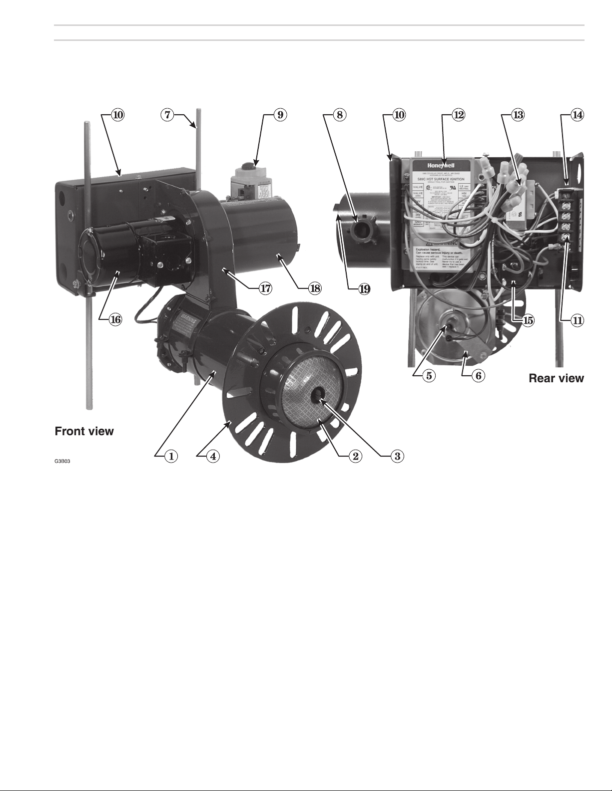
G3B Gas burner at-a-glance
1 Air tube, with powder coat paint fi nish
2 Flameholder
3 Hot surface ignitor
4 Adjustable fl ange
5 Rear ignitor assembly with terminal boots
6 Ignition tube assembly mounting plate
7 Pedestal legs
8 Burner gas inlet connection (see page 8)
9 Combination gas valve (with integral gas pressure regulation — set
for 3½” w.c. outlet pressure)
10 Control panel
11 Terminal strip
Carlin part number MNG3B Gas Rev. 03/17/09
12 Primary control (Honeywell Model S89C primary control, for use with
fl ame rectifi cation)
13 Control transformer, 120
14 Gas valve on indicator light
15 Motor relay
16 High-effi ciency motor
17 Blower housing (cast aluminum), with powder coat paint fi nish
18 Air inlet tube assembly
19 Air throttle indicator — Only a single adjustment required for setting
combustion air; see page 8 for starting setting based on appliance
model and input)
VAC / 24 VA C, 40 VA
3
Model G3B Gas burner — Instruction manual
1. Prepare site • prepare burner • mount burner
Inspect installation site
Inspect, repair and/or replace vent system
Do not install this burner unless you have verifi ed the entire
vent system and the appliance are in good condition and
comply with all applicable codes. And . . .
The vent and chimney must be sized and constructed in
accordance with all applicable codes. If intended for use
with an oil burner as well, the vent system must comply with
relevant codes for both gas and oil fi ring.
The vent system must not be pressurized unless the vent
piping and vent system are designed accordingly. The vent
must provide draft at all times (negative pressure in vent).
Do not install or use an existing manual damper in the vent
connector or vent.
Do not connect the appliance vent connector to a chimney
or vent serving a fi replace, incinerator or solid-fuel-burning
apparatus.
In a cold climate, do not vent into a masonry chimney that
has one or more sides exposed to the outside. Install a listed
stainless steel liner to vent the fl ue products.
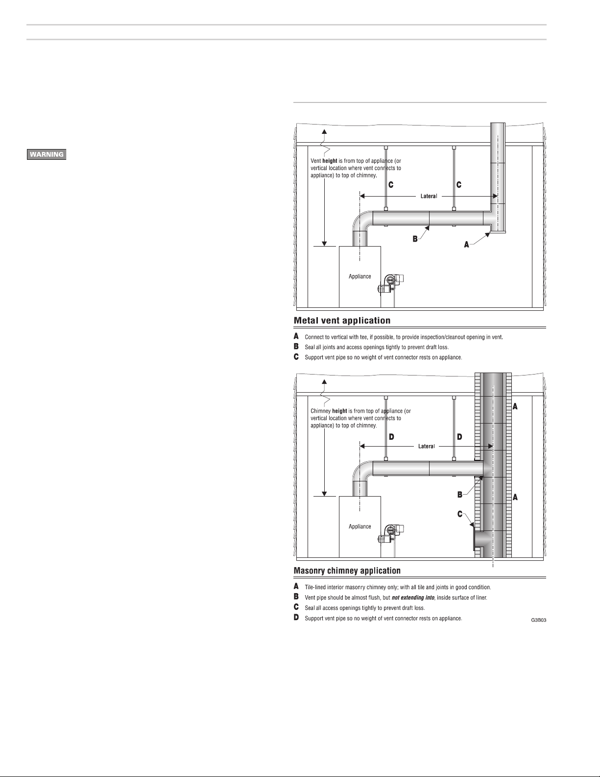
Figure 1 Vent and vent connector installation
A defective vent system could result in severe personal injury,
death or substantial property damage.
Vent/chimney sizing
• Follow all local codes when sizing the vent and chimey
• Refer to the appliance manufacturer’s manual, when available, for
venting recommendations
Prepare vent/chimney
• Secure all metal vent joints with screws, following the vent manufacturer’s instructions. Seal all joints in the vent system and chimney. Repair
masonry chimney lining and repair all mortar joints as needed.
• Install a double-acting barometric draft regulator in the vent piping. (The
damper must be located in the same space as the appliance.) Install a
manual reset spill switch in the top of the draft regulator outlet. Wire the
switch into the appliance limit circuit to shut off the appliance/burner if
sustained downdraft should occur.
• Provide support for the vent piping. Do not rest the weight of any of the
vent piping on the appliance fl ue outlet.
Verify clearances
• Verify that clearances required for service/maintenance comply with
the appliance manual and applicable codes. Provide at least 6 inches
around burner and 24 inches in front of burner panel for service
access.
4
Carlin part number MNG3B Gas Rev. 03/17/09
Model G3B Gas burner — Instruction manual
1. Prepare site • prepare burner • mount burner (continued)
Inspect installation site
Combustion/ventilation air openings
Installing the burner/appliance in a space that does not provide
enough air for combustion and ventilation can result in severe
personal injury, death or substantial property damage. Follow
all applicable codes and guidelines below to ensure space has
suffi cient air openings.
Large spaces
For appliances located in basements, ventilated crawl spaces or other large
areas, no additional air openings should be necessary.
Exception: If the building construction is unusually tight (see National Fuel
Gas Code or CSA B149.1 or .2 for defi nition), you will need to provide air
openings into the building if appliance air comes from inside. Provide one
opening within 12 inches of the ceiling, and one opening within 12
inches of the fl oor. Size each opening to provide free area (after deduction
for louvers) of 1 square inch per 1,000 Btuh input of all fuel-burning
appliances in the building.
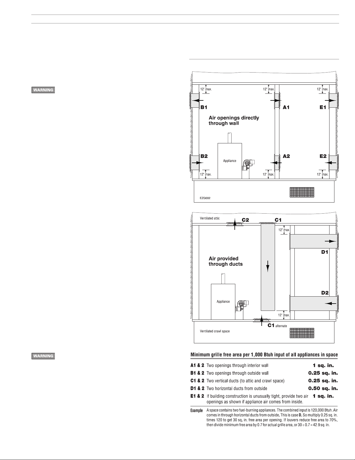
Confi ned spaces — air from inside building
If air openings connect to areas inside the building, provide two openings,
one within 12 inches of the ceiling, the other within 12 inches of the fl oor.
Each opening must have a free area (after deduction for louvers) of 1 square
inch per 1,000 Btuh of all appliances in the space. If the building construction is unusually tight (see National Fuel Gas Code or CSA B149.1 or .2 for
defi nition), you will need to provide air openings into the building. Provide
two openings sized and located as for the openings into the boiler space.
Figure 2 Locating & sizing air openings
Confi ned spaces — air from outside
If air openings connect directly to outside, provide two openings, one within
12 inches of the ceiling, the other within 12 inches of the fl oor. Each opening
must have a free area (after louver deduction) of:
• If directly through side wall: 1 square inch for each 4,000 Btuh of all
appliances in the space.
• If through vertical ducts: 1 square inch for each 4,000 Btuh of all
appliances in the space.
• If through horizontal ducts: 1 square inch for each 2,000 Btuh of all
appliances in the space.
Verify openings
When sizing air openings for combustion and ventilation, include
air required for exhaust fans and other appliances, such as
clothes driers, that require air for operation.
Check appliance manual and applicable codes for required sizing of
combustion and ventilation air openings.
• Verify that openings are unobstructed.
• Verify that appliance space and air source spaces are free of:
– gasoline or other fl ammable liquids or vapors.
– combustible materials.
– air contaminants, such as laundry products, paint, thinner, varnish, etc.
• Confi rm with user that the area will be kept free of these materials at
all times.
Carlin part number MNG3B Gas Rev. 03/17/09
5
Model G3B Gas burner — Instruction manual
1. Prepare site • prepare burner • mount burner (continued)
Prepare the appliance
Burner input: Install a gas burner sized for the normal input
rating of the appliance. Do not install a burner with a higher
fi ring rate than the appliance rating. Do not install a burner
with a fi ring rate more than 10% lower than the appliance
rating. The appliance and vent system could be damaged
due to condensation.
Seal the appliance: Seal all fl ue-gas containing joints. Seal
all connections to the vent piping or breeching.
Clean and check the appliance: Clean the appliance
thoroughly. Test all electrical components and verify the
relief valve works (boilers only).
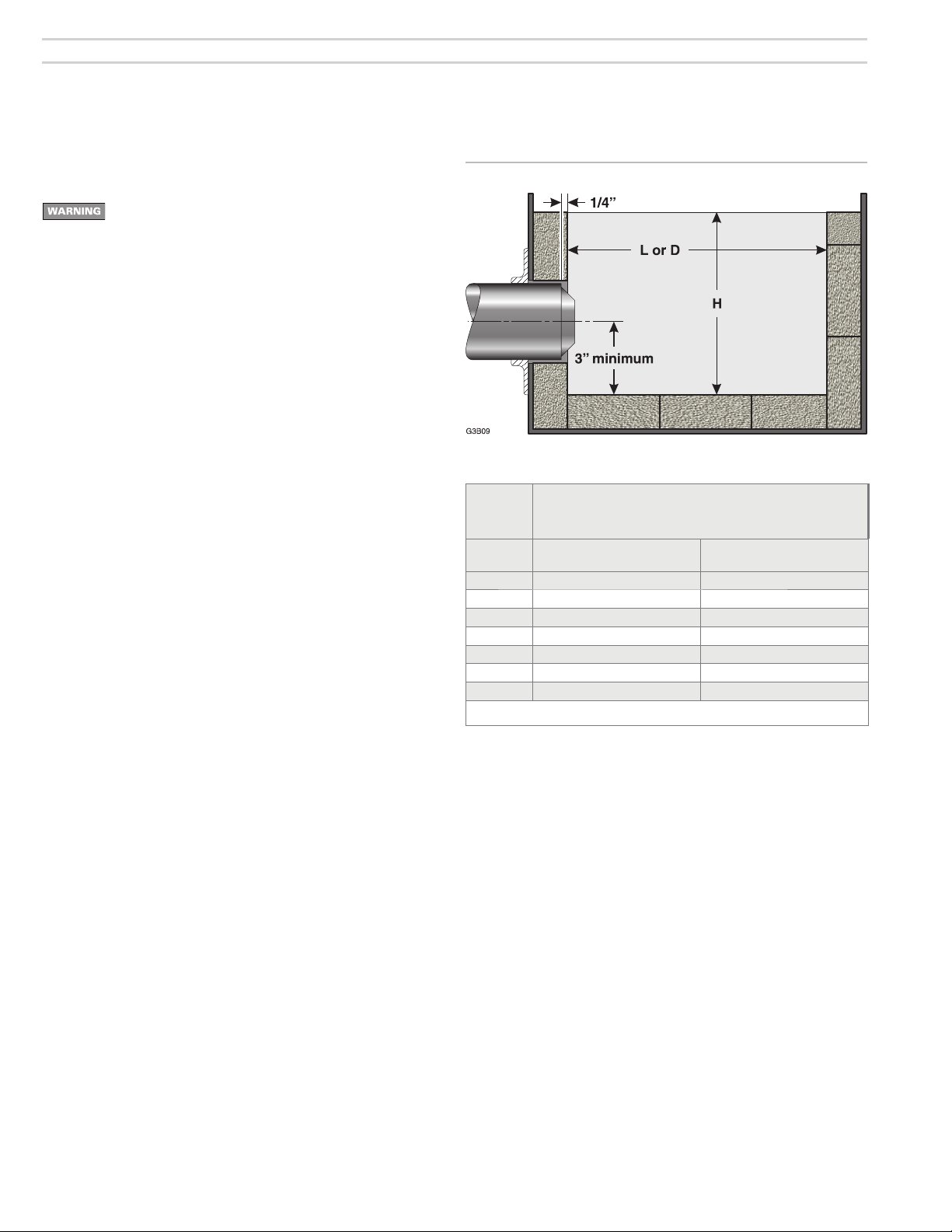
Verify combustion chamber dimensions comply with the
minimum dimensions shown in Figure 3. Install or replace
combustion chamber liner if required by the appliance
manufacturer. The burner air tube must not extend into the
combustion chamber. The end of the burner air tube must be
within ¼” of the inside face of the combustion chamber. If the
space around the burner air tube is more than ¼”, wrap the
burner air tube with minimum 2300-°F-rated ceramic fi ber
blanket to seal off the gap. Notice that the fl ameholder may
extend slightly into chamber as shown in Figure 3.
Repair or replace damaged appliance components. Inspect
the appliance thoroughly. Follow appliance manufacturer’s
guidelines for repair or replacement of any component found
defective.
When cleaning the appliance or working with ceramic fi ber
refractories or fi berglass insulation, see WARNING on page
7.
Figure 3 Minimum combustion chamber dimensions
Input Minimum chamber dimensions, Inches
(Note 1)
Btuh
60,000 7 x 7 x 9 8 x 9
70,000 7½ x 7½ x 9 8½ x 9
100,000 8 x 8 x 9 9 x 9
120,000 9 x 9 x 9 10 x 9
140,000 10 x 10 x 9 11 x 9
160,000 11 x 11 x 9 12 x 9
180,000 12 x 12 x 9 13 x 9
Note 1: Rectangular chambers of similar fl oor area are equally acceptable, but the L/W ratio should not
exceed 2 and the width should be at least 5 inches.
(Using 2300ûF or higher refractories)
Square
L x W x H
Vertical cylinder
Diameter x H
Failure to comply with the above could result in severe
personal injury, death or substantial property damage.
6
Carlin part number MNG3B Gas Rev. 03/17/09

Model G3B Gas burner — Instruction manual
1. Prepare site • prepare burner • mount burner (continued)
Inspect burner and components
Do not install or operate the burner if any component is
damaged or if burner does not comply with the specifi cations
and guidelines in this manual and the appliance manual.
Air tube insertion length (UTL)
• Usable air tube length (UTL) is the distance from mounting fl ange to
end of air tube.
• Verify that the end of the air tube will be fl ush with, or no more than
¼ inch short of, the inside of the appliance combustion chamber front
wall when the burner is mounted. See Figure 3, page 6.
• Minimum UTL is 1¾ inches. Maximum UTL is tube length less 1¾
inches. Tubes are available in 6-inch, 9-inch and 12-inch lengths.
• Notice that the fl ameholder may extend slightly into chamber as
shown.
Prepare appliance for burner mounting
The universal fl ange supplied with G3B Gas burners is
intended only for fi ring chambers with negative overfi re
pressure. The G3B burner must not be installed on a product
that operates with a pressurized combustion chamber. Failure
to comply could result in severe personal injury, death or
substantial property damage.
Ceramic fi ber or
Fiberglass insulation
Ceramic fi ber materials, such as chamber liners, may
contain carcinogenic particles (chrystobalites) after
exposure to heat. Airborne particles from fi berglass or
ceramic fi ber components have been listed as potentially carcinogenic by the State of California. Take the
following precautions when removing, replacing and
handling these items.
Avoid breathing dust and avoid contact with skin
or eyes. Wear long-sleeved, loose-fi tting clothing,
gloves and eye protection. Use a NIOSH N95 certifi ed
respirator. This respirator meets requirements for
protection from chrystobalites. Actual job requirements
or NIOSH regulations may require other or additional
protection. For information, refer to the NIOSH website,
http://www.cdc.gov/niosh/homepage.html.
Ceramic fi ber removal: To prevent airborne dust, thor-
oughly wet ceramic fi ber with water before handling.
Place ceramic fi ber materials in a plastic bag and seal
to dispose.
• See page 21 for required dimensions and bolt locations.
Avoid blowing, tearing, sawing or spraying fi ber-
glass or ceramic fi ber materials. If such operations are
necessary, wear extra protection to prevent breathing
dust.
Wash work clothes separately from other laundry.
Rinse clothes washer thoroughly afterwards to prevent
contamination of other clothing.
NIOSH First aid procedures:
Eye exposure — irrigate immediately
Breathing — fresh air.
Carlin part number MNG3B Gas Rev. 03/17/09
7
Model G3B Gas burner — Instruction manual
1. Prepare site • prepare burner • mount burner (continued)
Inspect burner and components
Drill or ream gas orifi ce to size (initial installation)
You must disconnect power to burner and close main manual
gas valve before proceeding. Failure to do so could result
in severe personal injury, death or substantial property
damage.
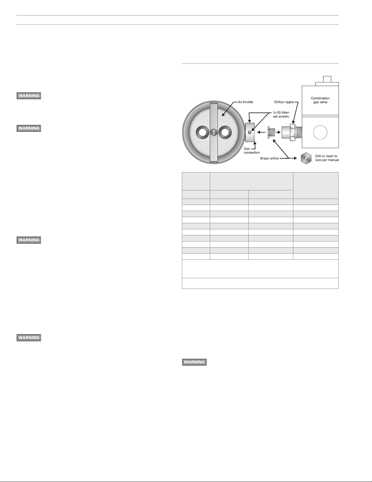
You must drill or ream the burner orifi ce to the size given in
Figure 4. The orifi ce is shipped with a pilot hole only. Firing the
burner with the orifi ce as shipped can result in damage to the
burner. Never fi re the G3B burner below 60,000 Btuh input.
The fl ameholder can overheat, resulting in potential severe
personal injury, death or substantial property damage.
1. After drilling or reaming orifi ce to correct size, thread orifi ce fi tting into
orifi ce nipple as shown in Figure 4.
Install gas valve on burner
1. Read WARNING’s on page 9 before installing gas valve.
2. Apply a small amount of pipe dope (suitable for propane gas) to gas
valve outlet connection, gas line elbow and orifi ce nipple. Assemble
elbow and orifi ce nipple to gas valve.
To avoid damage to gas valve, do not hold valve with a pipe
wrench or over-tighten. Use only a crescent wrench or other
means. Failure to comply could result in severe personal
injury, death or substantial property damage.
3. Insert orifi ce nipple into burner gas connection and secure in place
using the two Allen screws.
4. Connect gas valve wires to gas valve.
Inspect/redrill gas orifi ce when required
1. Turn off power to the burner/appliance before proceeding.
2. Close main manual gas valve in gas line to burner. Then disconnect the
ground joint union to allow rotating burner combination gas valve.
You must disconnect power to burner and close main manual
gas valve before proceeding. Failure to do so could result
in severe personal injury, death or substantial property
damage.
3. Loosen Allen screws securing gas line to burner gas connection.
4. Remove combination gas valve (item 9, page 3) and gas piping to burner
gas connection (item 8, page 3) on burner air tube.
5. Read correct orifi ce drill size from Figure 4. Then check actual orifi ce
size using that size twist drill bit.
• If gas orifi ce is smaller than required, redrill orifi ce to correct size,
if necessary. Replace gas valve and piping, using only pipe dope listed
for use with liquefi ed petroleum gases.
• If gas orifi ce is larger than required, obtain a replacement gas orifi ce
fi tting. Drill orifi ce hole in replacement orifi ce fi tting.
Figure 4 Orifi ce and gas valve installation
Input
Btuh
Note 1 Natural Gas Propane Gas
60,000 #28 (0.141) #33 (0.113) 0
70,000 #24 (0.152) ¹⁄₈ (0.125) ½
80,000 #20 (0.161) #30 (0.129) ¾
90,000 #17 (0.173) #28 (0.141) 1
100,000 #14 (0.182) #25 (0.150) 1½
110,000 #11 (0.191) #22 (0.157) 1¾
120,000 #7 (0.201) #20 (0.161) 2¼
140,000 #3 (0.213) #16 (0.177) 3
160,000 A (0.234) #12 (0.189) 4¼
180,000 D (0.246) #7 (0.201) 9
Note 1: High altitude applications: The maximum burner input at sea level is 180,000 Btuh.
Note 2: Use this as the starting setting only. Adjust air throttle, if necessary, after performing
Burner orifi ce drill size
Diameter, inches
Reduce this capacity by 4% per 1,000 feet above sea level. Example — max.
capacity at 5,000 feet is 144,000 Btuh (20% reduction).
combustion testing (see page 14).
Air throttle
turns (appr.)
Notes 1 & 2
Hot surface ignitor
• Inspect the burner from air tube end. The hot surface ignitor must extend
slightly past the end of the burner.
• Carefully inspect the ignitor, ensuring it is intact, with no cracks or visual
signs of degradation.
• Do not touch the ignitor with bare hands. Body oils can cause deterioration
of the silicon carbide.
• Replace ignitor if there are any signs of damage.
You must allow ignitor to cool before attempting to handle.
Failure to do so could result in severe personal injury or
damage to the ignitor.
Inspect components and wiring
• Visually inspect all burner components and wiring.
• Verify that wiring is intact and leads are securely connected.
• Verify that all burner components are in good condition.
Mount burner in appliance
• Verify appliance burner front plate dimensions per page 21.
• Slide gasket supplied with burner over end of air tube.
• Insert burner into appliance opening and bolt in place.
8
Carlin part number MNG3B Gas Rev. 03/17/09

Model G3B Gas burner — Instruction manual
2. Install gas piping from meter to combination gas valve
Code compliance
The burner/appliance installation must comply with codes listed on page 2 and
any other locally applicable codes.
Piping from meter to burner
Connect from the gas supply to the burner combination gas valve
inlet using new, clean black iron pipe and malleable iron fi ttings only.
Do not use copper, brass, cast iron or galvanized pipe or fi ttings.
Provide support for gas piping. Do not rest weight of piping on burner
gas valve.
Apply pipe dope sparingly at all joints. Use only pipe dope listed for
use with propane gas. Do not use pipe sealing tape.
Do not hold gas valve with pipe wrench. Use crescent wrench or
other smooth-jawed device. Do not over-tighten.
Failure to comply with above could result in severe personal injury,
death or substantial property damage.
1. If possible, install a new gas line directly from the gas meter. If you
are using an existing gas line, verify it is clean and in good condition,
and verify it is large enough to handle the load of all connected appliances.
2. When branching from a common gas line, do not tap off from the bottom
of horizontal sections — only from the side or top.
3. Install a main manual shutoff valve, sediment trap and ground joint
union near the burner combination gas valve connection as shown in
Figure 5.
4. If the burner is installed inside the appliance jacket, install the main
manual gas valve and sediment trap external to the jacket.
5. Size piping (or verify size) using Table 2. You will fi nd additional information on gas line sizing in the National Fuel Gas Code, ANSI Z223.1.
Gas supply pressure — natural or propane
• Maximum supply pressure: 14 inches w.c.
• Minimum supply pressure: 5 inches w.c.
Do not expose the combination gas valve to gas pressure in
excess of 14 inches water column. Higher pressure could
damage the valve seat, resulting in potentially hazardous
condition. When pressure testing piping at higher pressures,
disconnect burner from gas line before testing.
If the gas supply pressure can exceed 14 inches water
column at any time, you must install a lockup type gas
pressure regulator in the gas supply piping, ahead of the main
manual gas valve installed at the burner.
Test and purge gas line
Read WARNING above.
Pressure test and purge the line. Pressure testing should be done by the
gas supplier or utility, following all applicable codes.
Table 2 Capacities of black iron pipe, cubic feet gas/hour
Figure 5 Connecting gas supply piping to burner
1 Pipe to meter or branch
2 Main manual gas shutoff valve (must
be ‘T’ handle in state of MA)
3 Use clean, burr-free black iron pipe
and malleable iron fi ttings
4 Ground joint union
Carlin part number MNG3B Gas Rev. 03/17/09
5 Sediment leg
6 Burner combination gas valve
7 Upstream pressure tap, 1/8”
8 Outlet pressure tap, 1/8” NPT
9 Gas pressure regulator access screw
10 Gas valve wire terminal strip
NPT
9

Model G3B Gas burner — Instruction manual
3. Wire burner
Code compliance
The burner/appliance installation must comply with codes listed on page
2 and any other locally applicable codes.
General wiring requirements
Read and follow the guidelines in this manual. Failure to
comply could result in severe personal injury, death or
substantial property damage.
Electrical shock hazard — Disconnect electrical supply to the
burner before attempting to service. Failure to comply could
result in severe personal injuiry, death or substantial property
damage.
Figure 6 Ladder wiring diagram
Electrically ground burner — The burner must be grounded
in accordance with local codes or, in the absence of local
codes, with the National Electrical Code, ANSI/NFPA 70 (in
Canada, the Canadian Electrical Code Part 1, C.S.A. Standard
C22.1.)
Label all wires before removing for servicing. Wiring errors
could result in unsafe appliance/burner operation.
Read appliance manufacturer’s instructions completely before
wiring burner.
Check polarity carefully. If hot and neutral wires are reversed
at appliance power source, the control will not operate.
If replacing any of the wire supplied with the burner, use
minimum #14 AWG 125°C or better.
10
Carlin part number MNG3B Gas Rev. 03/17/09

Model G3B Gas burner — Instruction manual
3. Wire burner (continued)
Verify power supply
1. The burner requires a 120VAC/60HZ/single-phase power supply. The
current draw will be aproximately 8.0 amps. Protect line with a 10-amp
or 15-amp fuse or breaker.
Figure 7 Wiring diagram — wire routing
Control panel enclosure
Wh
Yel
BlueBk
Yel
Yel
Honeywell S89C
control
GND (BURNER)
24V (GND)
24V
VALVE (GND)
VALVE
L1
Gray
Blue
HSI
HSI
Gn
Yel
Red
Or
Br
Bk
40
VA
Transformer
2. The 120
shown in Figure 7. The control is polarity-sensitive, and will not work if
the hot and neutral lines are reversed.
3. Verify that the power supply to the burner is no less than 102
more than 132 VAC.
VAC power connections to the burner must be connected as
**
Supplied by installer
Line switch **
Thermostat **
Spill switch (if used)
(may also be wiring in
the 120-v limit circuit)
Bk
Wh
Yel
Red
Gn
Pur
Pur
Gnd
L1
L2
T
T
Valve on
light
NOTICE: Line voltage polarity
The hot and neutral power wires
must connect as shown for correct
operation of the burner controls.
120-v limit
circuit
120 VAC
**
VAC nor
GND
Hot
Neu
Wh
L2
Bk
Hot surface
Bk
ignitor
BkBk
MV MV
G3B01
Carlin part number MNG3B Gas Rev. 03/17/09
TH/TR
Bk
Red
Motor
end switch
Combination
gas valve
Motor
relay
Red
Bk
Red
Wire color coding
Bk = black
Blue = blue
Terminal
strip
120 factory wiringVAC
24 factory wiringVAC
120 field wiringVAC
24 field wiringVAC
Wire connector
Bk
Connect ground wires
M
Motor
120
VAC
Or = orange
Br = brown
Gr = green
Pur = purple
Gray = gray
to green terminal strip
screws when replacing
a Fenwal control with a
Honeywell S89C.
Red = red
Wh = white
Yel = yellow
11

Model G3B Gas burner — Instruction manual
4. Check system • start-up burner/appliance
Inspect/check system
Before starting the burner and appliance, verify the system has been installed
as directed by this manual and the appliance instructions.
Check gas piping for leaks
Disconnect the burner from the gas supply line if gas line
test pressure will exceed 14 inches w.c. Exposing the burner
combination gas valve to pressure higher than 14 inches w.c.
can damage the valve seat, resulting in potentially unsafe
operation.
You can usually test the gas piping by allowing the line to fi ll with gas to
main regulator outlet pressure.
1. Shut off gas fl ow to all appliances connected to the meter.
2. If test pressure will be less than 14 inches w.c., turn the burner combi-
nation gas valve knob to OFF. If test pressure will be higher than 14
inches, disconnect the burner from the gas line by shutting off the
main manual gas valve installed near the burner (per Figure 5, page 9)
and disconnecting the ground joint union. See warning above.
3. Watch the gas meter dial. For a one half cubic foot per revolution dial,
there should be no movement of the dial for at least 5 minutes. For
larger volumes per revolution, increase this time proportionately.
Figure 8 Air throttle adjustment
6. The Figure 4 setting will probably be satisfactory without change. If the
combustion test indicates a need for more or less air, however, you will
have to adjust the throttle accordingly.
Check burner and Honeywell S89C control
Inspect burner thoroughly. Verify all components are secure and burner
is in good condition. Verify all wiring is in place and all components are
secure and in position.
Verify fl ame failure lockout of Honeywell control
4. If you detect a gas leak, locate the leak with a soap suds mixture and
repair it. Then test the system for leaks again.
Do not test for leaks with an open fl ame. And do not use
oxygen as a test gas. Either of these could cause an
explosion, resulting in severe personal injury, death or
substantial property damage.
Bleed gas line
Purge all air from the gas line. Purge to outside of the building, NEVER into
the appliance or burner.
Leak test near-burner gas piping
If piping near burner has not already been pressure tested, open main
manual gas valve on supply to burner and smell around area for any signs of
gas. Apply a soap suds mixture to all gas piping joints near burner and check
for any leaks. If any leaks appear, repair before proceeding and retest.
Set air throttle
1. See Figure 8. Loosen air throttle locking nut.
2. Rotate the air throttle plate clockwise to the closed position.
3. Check the air throttle indicator. The “0” position of the indicator should
be even with the end of the air inlet tube. If not, bend the arm slightly
until the indicator reads zero.
4. Rotate air throttle until indicator points to setting given in Figure 4,
page 8.
5. Tighten air throttle locking nut.
1. Install a hose barb fi tting in the combination gas valve outlet pressure tap
and connect with a hose to a U-tube manometer.
2. Close the main manual gas valve and turn the combination gas valve knob
to ON.
3. Turn on power to appliance and set appliance limit(s) to call for heat.
4. Burner motor will start. The Honeywell S89C control will run the blower for
34 seconds (pre-purge and ignitor warm-up). Then the combination gas
valve will open and the “Valve on” light will light. (The manometer should
show almost no pressure, because the main manual gas valve is closed.)
5. After 6 seconds, the S89C will lockout. The ignitor will shut off and the gas
valve will close. Turn off power or interrupt thermostat circuit for 45 seconds.
The control should reset. Turn off power and set controls to stop call for
heat.
6. If lockout does not occur, replace the S89C control.
Do not start the burner if you smell gas or if there may be gas
present in the appliance combustion chamber, heat exchanger
or the vent system. An explosion could occur, causing severe
personal injury, death or substantial property damage.
During initial start-up, you must be constantly alert for
emergency conditions such as fuel leaks, electrical malfunctions, etc. Familiarize yourself with the location of manual
shutoff valves and switches so you can quickly use them if
needed.
If the burner fails to ignite, NEVER attempt to manually bypass
the normal sequence of the control, which provides purging
of the combustion chamber.
12
Carlin part number MNG3B Gas Rev. 03/17/09

Model G3B Gas burner — Instruction manual
4. Check system • start-up burner/appliance (continued)
Installer/servicer
Should overheating or an emergency occur, immediately:
• Shut off main manual gas valve.
• Shut off power to burner.
NOTICE: Under some circumstances power should remain
on for water pumps or circulating blowers. Determine proper
response before attempting start-up.
If burner fails ignition on several attempts, close gas valve
and use burner blower to purge appliance before restart.
Before starting burner, verify:
❏ Burner/appliance installed per appliance instruction manual?
❏ Burner orifi ce size and air throttle verifi ed against Figure 4, page 8?
❏ Burner/appliance installed per all applicable codes?
❏ Installation site has adequate ventilation openings and vent
system?
❏ Gas supply line in good condition and sized correctly?
❏ All gas line joints sealed with pipe dope listed for use with liquefi ed
petroleum gases?
❏ Gas supply pressure to combination gas valve checked?
❏ Regulator installed if pressure can exceed 14 inches w.c.?
❏ Air purged from gas line?
❏ Gas piping checked for leaks?
❏ Wiring installed per burner and appliance instruction manuals?
Ignition and fl ame sensing
Ignition The G3B burner uses a silicon carbide hot surface ignitor
for ignition. The Honeywell S89C primary control feeds 120
VAC power to the ignitor and allows time for the ignitor to
warm up to ignition temperature during the burner pre-purge
period.
Sensing The S89C primary control uses fl ame rectifi cation to detect
fl ame, with the hot surface ignitor acting as the “fl ame
rod.”
Start-up & operation
Do not start the burner if the combustion chamber contains
residual gas. Allow gas to disperse. Failure to comply could
result in severe personal injury, death or substantial property
damage.
Power ON Open all manual gas line valves. Turn burner combination gas
valve knob to “ON.” Close the line switch. (If burner does not
follow sequence below, see troubleshooting suggestions on
pages 19 and 20.)
Stand-by (No call for heat) Control waits for heat call.
Call for heat Set operating control and all limit controls to call for heat.
The thermostat circuit must be closed and power coming to
control panel L1 and L2 terminals
Burner on The motor starts. The hot surface ignitor starts. The motor
centrifugal switch makes.
Pre-purge The primary control allows 34 seconds for pre-purge and
ignitor warm-up.
Gas valve on After the pre-purge/ignitor warm-up period, the primary
control activates the gas valve (if motor centrifugal switch
is closed). The green “Gas valve on” light turns on.
TFI The primary control turns off the ignitor within 2 to 6 seconds
after gas valve activation. When the control deactivates the
ignitor, it begins checking for fl ame signal. If fl ame is not
detected within 6 seconds after gas valve activation, the
primary control will lockout with continuous purge (see
following).
Run period The burner continues fi ring during call for heat if the fl ame
rod (hot surface ignitor) senses fl ame. The green “Gas valve
on” light remains on during normal running, indicating gas
valve is energized.
Shutdown When the call for heat ends, the primary control immediately
deactivates the gas valve and blower. The burner returns to
stand-by.
Flame failure If the primary control loses fl ame signal during a run period,
it deactivates the gas valve within 2 seconds. The control
restarts the heating cycle, beginning with a 34-second
pre-purge/ignitor warm-up period, then a 6-second trial for
ignition. If ignition/fl ame sensing is successful, the burner
returns to normal operation. If the attempt is not successful,
the primary control will lockout.
Lockout If the primary control does not sense fl ame within the TFI
time limit after gas valve activation (6 seconds), lockout
occurs. The control deactivates the gas valve. The blower
motor continues to run, providing a post-purge of the burner
and appliance.
Reset To reset after a lockout, turn off power to burner or interrupt
the thermostat circuit for at least 45 seconds. Then restore
power (or thermostat circuit). Burner should restart.
Carlin part number MNG3B Gas Rev. 03/17/09
13

Model G3B Gas burner — Instruction manual
5. Perform checkout procedures • fi ll out certifi cate
Make fi nal burner adjustments
Check for leaks in gas piping
❏ Smell around burner to make sure there is no gas leak in near-burner
piping. Verify integrity of gas line joints between combination gas
valve and burner gas inlet tapping using soap suds mixture. Verify
gas piping is fully supported, independently of burner.
Check for leaks from burner components
❏ Smell around burner to make sure there is no leakage from the burner
inlet air tube, blower housing or air tube. Verify burner is properly
supported and fl ange is securely tightened.
If you detect leakage from any burner component, immediately
close the main manual gas valve. Use a soap suds mixture to
determine leakage location. Replace burner if leakage cannot
be corrected by properly securing components. You may have
to restart the burner several times during leakage testing
since the control will lockout when fl ame is not detected.
Failure to correct leakage problems could result in severe
personal injury, death or substantial property damage.
Make fi nal burner adjustments (continued)
Check/adjust gas valve outlet pressure
❏ With burner running, check manometer reading for combination gas
valve outlet pressure. Adjust valve regulator if necessary so the
reading is 3.5 inches w.c. for either natural gas or propane gas.
Inspect fl ame
❏ Look at fl ame through appliance observation port. The fl ame should
be a soft blue with well-defi ned orange and yellow tips for natural
gas, or well-defi ned yellow tips for propane gas. (If you make air or
gas pressure changes later, inspect the fl ame again.)
Check the fi ring rate
❏ Natural gas only — Turn off all other gas appliances connected to
the gas meter. Use a stopwatch to time the number of seconds for a
fl ow of one cubic foot of gas (two revolutions for a one half cubic foot
per revolution dial, for example). You will also need to know the gas
heat content in Btu per cubic foot. Determine the actual input from:
INPUT = (3600 x Btu per cubic foot) ÷ (number of seconds for one cubic
foot), for fi ring rate in Btuh. For example, for 1050 Btu per cubic foot
natural gas, with meter timed at 30.2 seconds for one cubic foot of
gas: INPUT example = (3600 x 1050) ÷ (30.2) = 125,200 Btuh. Firing
rate should be within ± 5% of rated input for the appliance. Adjust
the combination gas valve pressure regulator if necessary to obtain
the correct fi ring rate. Valve outlet pressure must not be lower than
3.2 inches w.c. nor higher than 3.8 inches w.c.
❏ For propane gas, contact your propane supply for procedure to verify
fi ring rate.
14
Carlin part number MNG3B Gas Rev. 03/17/09

Model G3B Gas burner — Instruction manual
5. Perform checkout procedures • fi ll out certifi cate (continued)
Make fi nal burner adjustments (continued)
Check combustion using instruments
You must use combustion test instruments. Failure to properly
verify/adjust combustion could allow unsafe operation of the
burner, resulting in severe personal injury, death or substantial
property damage.
CO
Fuel
Natural Gas 9.6% 10.8% 4.0% 2.0%
Propane Gas 11.0% 12.5% 4.0% 2.0%
Minimum Maximum Maximum Minimum
2
O
2
❏ Insert test probe into vent above appliance to sample fl ue products.
The results should show CO2 or O2 as follows:
❏ If the combustion results are outside the range above, and the fi ring
rate of the burner is within 5% of rated input, open or close the air
throttle until the CO
After CO2 (O2) tests are completed satisfactorily, measure
fl ue products for carbon monoxide (CO) concentration. The
CO must not exceed 50 ppm adjust to “air free”, or other if
specifi ed by local codes.
(or O2) are acceptable.
2
Make fi nal burner adjustments (continued)
Check fl ame signal
Electrical shock hazard — Turn off power to burner before
proceeding with setup for fl ame signal measurement.
❏ (See Figure 9.) The HSI is powered with 120 VAC during pre-purge
so a microammeter with a shunt switch must be used to test fl ame
signal or the meter will be destroyed. USE ONLY needle movementtype meters, not digital meters.
❏ Remove the ignitor lead wire from HSI terminal of the S89C primary
control. Connect a shunt switch and
HSI terminal and the ignitor lead wire. Make sure shunt switch is
closed. Then turn on power to the burner. After the burner fl ame
starts, wait at least 15 seconds, then open shunt switch and read DC
amps (must be at least 0.8 microamps DC).
DO NOT start the burner or adjust the air throttle with the
shunt switch open. The 120 V supply to the HSI will destroy
the microammeter.
Figure 9 Flame signal measurement connections
DC microammeter between
❏ Adjust the draft in the appliance so the draft overfi re is about –0.01
inch w.c. and take a fl ue gas sample from the combustion chamber.
If CO
is noticeably lower overfi re than in the vent, the appliance has
2
leaks that must be repaired.
Carlin part number MNG3B Gas Rev. 03/17/09
15

Model G3B Gas burner — Instruction manual
5. Perform checkout procedures • fi ll out certifi cate (continued)
Verify burner/appliance operation
Check burner/appliance/controls operation
❏ Test operating and limit controls on appliance as specifi ed in appliance
instruction manual.
❏ Check operation of the S89C primary control, forcing lockout by
closing the main manual gas cock and cycling the burner. See page
13 for procedure to reset the control.
Verify burner operation
❏ Start and stop the burner several times, allowing the primary control
to sequence through normal operation. Verify correct operation of
burner and control throughout. See page 13 for burner sequence of
operation.
Verify vent system operation
❏ Verify vent is operating correctly and fl ue products are properly
exhausted from building.
❏ Check operation of barometric damper and spill switch.
❏ If the building contains any exhaust fans or conditions that could
affect vent performance, check burner/appliance/vent operation with
exhaust fans (or other conditions) operating.
Prepare burner for normal operation
❏ Cycle burner off with appliance controls. Then turn off power to the
appliance.
❏ Close the main manual gas valve.
❏ Remove the U-tube manometer line from the combination gas valve
outlet pressure tap hose barb. Remove hose barb and replace 1/8"
NPT pipe plug in tapping.
❏ Verify all components and wires are in place and burner is ready for
operation.
Train the user
❏ Train the user to operate the burner and appliance under normal
conditions. Explain procedure to shut down burner/appliance when
required.
❏ Review the user information section of this manual (and the appliance
manual) with the user.
❏ Verify the user is aware of all procedures specifi ed in the manual.
❏ Verify user will not store or use combustible liquids or materials or
contaminants in the vicinity of the burner/appliance.
16
Carlin part number MNG3B Gas Rev. 03/17/09

Model G3B Gas burner — Instruction manual
6. Maintenance and service procedures
Annual start-up & service
This burner should be started and serviced at least annually
by a qualifi ed service technician. Failure to properly maintain
and service the burner could result in severe personal injury,
death or substantial property damage.
Turn off power to appliance and close main manual gas
valve when servicing burner. See WARNINGS on page 2
and elsewhere in this manual regarding correct procedures.
Failure to comply could result in severe personal injury, death
or substantial property damage.
❏ Discuss burner/appliance operation with user to determine any prob-
lems that may have occurred during the previous season and to verify
user is aware of proper operation and care of the burner/appliance.
❏ Turn off power to appliance and close main manual gas valve.
❏ Remove burner from appliance and inspect fl ame holder, hot surface
ignitor and burner components.
❏ Inspect ignitor and ignition tube assembly.
1. The hot surface ignitor (HSI) is a silicon carbide element that performs dual
functions of ignition and fl ame detection. On a call for heat, the ignitor
is powered with 120 vac and is electrically heated to about 2600°F. This
ignites the gas/air mixture when the primary control energizes the gas
valve.
2. The primary control then switches the HSI to the fl ame detector circuit,
using fl ame rectifi cation to monitor the fl ame.
3. The ignitor is positioned in the ignition tube assembly against a factoryset non-adjustable stop ring for proper ignition and fl ame sensing.
4. To inspect the HSI, fi rst be sure the 120 vac power supply to burner is
disconnected. Then slide the two silicone insulating boots off of the
insulators.
5. Pull off the quick-disconnect terminals.
6. Remove the four #8-32 screws securing the air tube back plate.
Annual start-up & service (continued)
7. Swing the hold-on bracket away and carefully pull out the ignition tube
assembly.
As the white ceramic is exposed, support it using a rag. It
could be HOT. Do not let the hot surface ignitor element bump
into anything. Do not drop the assembly or ignitor element.
The element is very fragile. Even a small hairline fracture will
destroy the HSI.
8. If the ignitor element is damaged in any way, replace it with a new
one.
9. If replacing the ignition tube assembly in the burner, replace the back
plate gasket with a new one. Replace the hold-on bracket and screws.
Ensure the back plate gasket is sealed gas-tight to the burner air tube.
❏ Inspect and clean fl ameholder.
1. Remove the ignition tube assembly from the burner as described in the
steps for inspecting the hot surface ignitor.
2. Reach in and, with one fi nger through the center hole of the fl ameholder,
pull the fl ameholder out of the burner air tube.
3. Use a small brush to remove dirt and lint from the inside surface of the
fl ameholder. All holes must be clean and unobstructed.
4. If the fl ameholder is damaged, dented or defective in any way, replace
it with a new one.
5. Replace the fl ameholder in the air tube.
6. Replace the ignition tube assembly as described in the steps for inspecting
the hot surface ignitor. Be sure to install a new back plate gasket and
seal assembly to air tube gas-tight.
7. Follow the instructions on page 8 to inspect the hot surface ignitor.
If the inside surface of the air tube needs to be cleaned,
clean with a vacuum cleaner with brush attachment while
the ignition tube assembly is out of the burner.
❏ Check the burner fl ange gasket. It must be in good condition. Replace
gasket on burner fl ange and mount burner in appliance, securing to
mounting studs.
Carlin part number MNG3B Gas Rev. 03/17/09
❏ Perform the complete checkout procedures of pages 12 through 17,
including system inspection and checks.
17

Model G3B Gas burner — Instruction manual
6. Maintenance and service procedures (continued)
Maintenance/service procedures
Cleaning blower wheel
❏ Periodically inspect and clean the blower housing and wheel.
1. The best time to clean the blower housing and blower wheel is while
the ignition tube assembly is out of the air tube (see “Inspect ignitor and
ignition tube assembly”).
2. Remove the four #8-32 slotted screws in the motor mounting plate.
3. By pulling about 1 “ of slack in the motor wires from the control box, the
motor blower/wheel assembly can be pulled out and rotated to a good
position for cleaning the blower wheel.
4. With a small brush or pipe cleaner, remove all dirt from the blades in the
wheel.
5. With a clean rag, wipe out all the dirt from inside the blower housing.
6. Dirt that drops into the burner tube must be removed while the ignition
tube is out.
7. Replace the motor plate gasket with a new one.
8. Replace the motor blower wheel assembly, being very careful that the
gasket on the motor mounting plate makes a gas-tight seal against the
blower housing cover.
Maintenance/service procedures (continued)
Replacing blower motor or wheel
Follow this procedure to replace motor or wheel.
1. Remove the four #8-32 screws in the motor mounting plate.
2. Pull about 1” of slack in the motor wires from the control box. Then pull
out and rotate the motor/blower wheel assembly.
3. Loosen Allen set screw in blower wheel hub and take the wheel off the
motor shaft.
4. Remove four #8-32 nuts holding motor to mounting plate. Be sure to take
the four nylon washer seals from the motor studs and save for the new
motor. Also remove the nylon motor bushing. Save the motor bushing for
use with the new motor.
5. Disconnect the motor wires from their wire nuts in the control panel,
keeping track of their locations.
6. Connect the new motor wires to their proper terminals.
7. Place the four nylon washer seals on the new motor studs and assemble
the motor plate to the motor using the four nuts.
8. Replace the blower wheel with about 1/16” of shaft protruding beyond
the hub.
9. Replace the motor plate gasket with a new one.
10. Replace the entire assembly, making sure that the gasket on the motor
plate makes a gas-tight seal against the blower housing cover.
18
Carlin part number MNG3B Gas Rev. 03/17/09

Model G3B Gas burner — Instruction manual
7. Troubleshooting
Problem Possible
cause
WARNING
Burner motor will
not start
Burner prepurges for 34
seconds but
does not light
(continued on
next page)
120 V power Check 120 V at terminal strip. L1 - L2
24 V circuit Check that 24 V thermostat/circuit is calling for heat.
Incorrect wiring Check all fi eld and factory wiring.
Bad motor relay Check 24 V at motor relay. Relay should click (pull-in) on call for heat.
Bad motor If motor relay is good (see above) and wiring is correct, disconnect the
Bad primary
control
Incorrect air
setting
Wrong orifi ce
size
Manual gas shutoff valve closed
Manifold
pressure
Gas valve not
opening
Motor end switch
not making
Hot surface
ignition element
damaged
Corrective action
These procedures must only be performed by a qualifi ed service
technician. Use care when performing tests on electrically or
mechanically live parts. Disconnect power to burner/appliance and close
main manual gas valve when removing components for service. Failure
to comply could result in severe personal injury, death or substantial
property damage.
Check limit/operative circuit.
Check transformer output. Each “T” on terminal strip should read
approx. 24 volts to “G” ground.
Check continuity across contacts (N.O.) or each side of contact to L2 on
terminal strip should read 120 volts.
motor leads and power the motor directly with 120 V to check motor
operation.
If all above tests prove negative replace control.
For initial light-off set air throttle according to desired input.
Check orifi ce drill size.
Check supply line gas cock and manual shut-off valve on combination
gas valve.
Adjust regulator to 3.5 W.C. for natural gas and propane.
Check for 24 V valve coil during TFI. Indicator light should also be on.
Line pressure in excess of 14.0 W.C. can damage valve.
Check motor end switch.
Disconnect the two red leads in the panel coming from the motor end
bell. Check continuity during pre-purge. End switch will not activate if
motor is not running up to speed.
Element normally glows red within 20 seconds during pre-purge. Use
fl ame mirror to visually inspect.
Check for 120 V at rear of ignitor assembly during pre-purge.
If visual inspection cannot be done, remove element and power directly
with 120 V. Replace element if it does not glow red within 45 seconds.
Carlin part number MNG3B Gas Rev. 03/17/09
19

Model G3B Gas burner — Instruction manual
7. Troubleshooting (continued)
Problem Possible
cause
WARNING
Burner prepurges for 34
seconds but
does not light
(continued)
Burner lights but
primary control
locks out after TFI
Bad primary
control
Incorrect air
setting
Wrong orifi ce
size
Manifold
pressure
Inadequate gas
supply
Insuffi cient fl ame
signal
Improper draft Improperly adjusted air throttle setting for the fuel input.
Polarity Check 120 V at L1 on terminal strip.
Corrective action
These procedures must only be performed by a qualifi ed service
technician. Use care when performing tests on electrically or
mechanically live parts. Disconnect power to burner/appliance and close
main manual gas valve when removing components for service. Failure
to comply could result in severe personal injury, death or substantial
property damage.
Check for 24 V on valve lead on control during TFI.
Check for 120 V on HSI lead on control during pre-purge.
Replace primary control if either above tests show negative.
For initial light-off, set air throttle according to desired input.
Check orifi ce drill size.
Adjust regulator to 3.5 W.C. for natural gas or propane.
Line pressure requirements are: 5.0 W.C. for both natural and propane
fuels.
Line pressure in excess of 14.0 W.C. could damage combination gas
valve.
Watch line pressure gauge during TFI. If pressure drops below minimum
required when gas valve is energized look for partially closed gas cocks
in line, other appliances using the same supply or improperly adjusted
intermediate regulators.
If other appliances are on the same supply line and piping will not
sustain adequate pressure for all units on that piping, then it is
undersized. Check with gas utility.
Check fl ame signal. Minimum signal 0.8 DC microamps.
Over-fi re draft is normally -0.01 W.C. Refer to boiler/furnace
manufacturer’s recommendations for specially packaged units.
20
Carlin part number MNG3B Gas Rev. 03/17/09

Model G3B Gas burner — Instruction manual
8. Dimensions and mounting information
Figure 10 Dimensional data
Mounting burner to appliance
The universal fl ange supplied with G3B Gas burners is
intended only for fi ring chambers with negative overfi re
pressure. The G3B burner must not be installed on a product
that operates with a pressurized combustion chamber. Failure
to comply could result in severe personal injury, death or
substantial property damage.
Prepare the burner opening on the front of the appliance as shown in
Figure 11. See page 6 to determine the location of the fl ange on the burner
air tube. Tighten the fl ange locking screws fi rmly.
Figure 11 Universal fl ange mounting
Carlin part number MNG3B Gas Rev. 03/17/09
21

Model G3B Gas burner — Instruction manual
9. Replacement parts
Item
Description Part
number
1 Air Inlet Tube Assembly 50823
2 Air Throttle 50757
3 G3B Orifi ce, No. 33 drill (.113 dia.), Propane 60,000 BTUH, drill open for other rates 60582
4 Orifi ce Nipple 61663
5 Gas Valve, dual, 24-volt (1/2” X 1/2” LH-outlet) 41053
6 Gasket, mounting fl ange 40287
7 Air Tube/Flange Assembly, 3-3/4 ID Flame Ring G3B 6”, overall length approx. 9-7/8”
G3B 9”, overall length approx. 12-7/8”
G3B 12”,overall length approx. 157/8”
8 Air Tube Housing Clamp (2 required) 50807
9 Flameholder 57117
10 Ignition Tube Assembly with gasket 6”, overall length approx. 10-9/16”
9”, overall length approx. 13-9/16”
12”, overall length approx. 16-9/16”
11 Gasket, motor mounting ring & air tube back plate (2 required) 40402
12 Electrode Hold-in 54858
13 Insulator Tube (2 required) 74617
number
50070
50112
50021
97875
97876
97877
14 Hot Surface Ignitor, NORTON 120-volt, 5-3/8” OAL 87197S
15 Gasket, ignitor assembly 40360
16 Rear Ignitor Assembly 6”, overall length 7-1/2”
9”, overall length 10-1 /2”
12”, overall length 13-1 /2”
17 Ignition Terminal boot (2 required) 9788401
18 Housing and cover plate (with liquid gasket) 45856
19 Blower Wheel, 4” OD x 1” wide, 5/16” bore, CCW rotation facing open end 28613
20 Motor Mounting Ring 51060
21 Bushing, motor shaft, nylon 34686
22 Washer, motor stud, nylon (4 required) 30577
23 Burner Motor, 1/50 hp, 3300 rpm, 115-volt, 60-hz, permanent split capacitor with centrifugal
switch, CCW rotation facing shaft
24 Control Panel Base 61028
25 Indicator Light, 24-volt 33936
26 Pedestal Legs, 3/8” OD x 12” long (2 required) 61036
27 Control, Honeywell No. S89C hot surface ignition primary control, with 6 sec. TFI 99564
28 Transformer, 40-VA rating, 115-volt primary, 24-volt secondary 24315S
29 Terminal Block 33944
46631
46656
46615
27789S
30 Motor Relay, 24-volt coil, SPST 35782
31 Control Panel Cover less nameplate 61150
22
Carlin part number MNG3B Gas Rev. 03/17/09

Model G3B Gas burner — Instruction manual
9. Replacement parts (continued)
Carlin part number MNG3B Gas Rev. 03/17/09
23

Model G3B Gas burner — Instruction manual
24
Carlin part number MNG3B Gas Rev. 03/17/09
 Loading...