

Carlin Flame Funnel 1050FFD, Flame Funnel 1150FFD Installation And Operating Instructions Manual

IT IS IMPORTANT THAT THE INSTALLATION OF
THE OIL BURNER, PIPING AND FITTINGS, SAFETY
DEVICES, CONTROLS, ELECTRICAL WIRING AND
EQUIPMENT BE DONE IN ACCORDANCE WITH NATIONAL AND/OR LOCAL REGULATIONS OF THE
AUTHORITIES HAVING JURISDICTION OVER SUCH
INSTALLATION.
Installation
and
Operating
Instructions
For
Carlin Flame Funnel®
Oil Burners
Models 1050FFD and
1150FFD
SPECIFICATIONS
MODEL NUMBER
ITEM
Fuel Specification No. 2
Firing Range
High-Fire*
Low-Fire
Motor HP, RPM, Hz 1, 3450, 60
Motor Volts, 1-phase
Motor Amps; 115 volts, 1-phase
Control Volts, Hz 120, 60 120, 60
Ignitor Volts 120 120
Burner Housing Rugged casting Rugged casting
Blower Wheel, Dia. x W. 7" x 5" 7
Flame Retention Ring, O.D. 3
2-Stage Fuel Unit Pressure 100 100
Low and High-Fire Oil Valve 120V, 60-Hz 120V, 60-Hz
Damper Motor with End Switch 120V, 60-Hz 120V, 60-Hz
Oil Nozzle Specs. (3) 45°SS (3) 45°SS
Approximate Shipping Weight 135 lbs. 145 lbs.
** Gph ratings are based on sea level to 2,000 ft. elevation. For every
1,000 ft. rise over 2,000 ft., reduce the maximum gph rating by 4%.
**Motor volts and phase must be specified when ordering.
3-phase
230 volts, 1-phase
230 volts, 3 phase
460 volts, 3 phase
1050FFD 1150FFD
ASTM D396
15.00-25.00*
9.00-12.00
115/208-230**
208-230/460**
16.4
8.2
4.0
2.0
13
/16" 41/4"
No. 2
ASTM D396
20.00-35.00*
12.00-15.00
1
1
/2, 3450, 60
115/208-230**
208-230/460**
22.0
11.0
5.0
2.5
5
/8" x 5"
Copyright 2016 — Carlin Combustion Technology, Inc.
©
Carlin Combustion Technology, Inc.
126 Bailey Rd North Haven, CT 06473
Ph 203-680-9401 Fx 203-680-9403
Tech Support 800-989-2275 carlincombustion.com
Description
Model 1050FFD and Model 1150FFD Flame-Funnel oil
burners for use with No. 2 fuel oil are low-high-low (step
modulating) high speed flame retention burners. Oil flow
rate is step-modulated by the use of two oil valves and
three nozzles, low-fire from the first nozzle and high-fire
added by the second and third nozzles firing simultaneously. Combustion air is controlled by a damper motor. Its end
switch energizes the second-stage valve as the air shutter
opens.
Due to the low-high-low feature of these burners they are
very versatile and efficient.
1. They can operate in forced draft boilers or furnaces at
pressures up to 0.50 inches W.C.
2. They will save typically, 20% in seasonal fuel consumption compared to conventional single-stage flame retention burners.
3. They can operate with or without refractory lined combustion chambers.
4. They are superior for process applications.
5. They can be installed through fire door openings.
Low-High-Low
(step-modulation) firing
Advantages: There are several strong advantages to lowhigh-low firing in both heating and process applications:
1. Smooth ignition both in natural and forced draft operations.
2. Closer control than with a single input.
3. Less strain or wear on the burner, boiler and combustion
chamber components:
a. Longer cycles.
b. Gradual changes; less thermal shock.
4. Lower fuel consumption:
a. Higher efficiencies of both low and high-fire.
b. Lower stand-by loss due to longer ON cycles and to
the closed air damper during OFF cycles.
Operation: A true low-high-low burner controls both air and
oil flow rates. A low-fire start burner (low-high-off) controls
only the oil rate and has a fixed air setting with none of
the preceding advantages. The low-high-low burner cycle
operates as follows:
1. Call for heat. Burner motor and ignition are energized. Air
is in the low-fire position. The low-fire oil valve admits oil
to the low-fire nozzle and its spray ignites, burning clean
with proper air/fuel ratio.
2. If demand exceeds low-fire, the damper motor is energized through a high-fire operating control (aquastat,
airstat, pressuretrol, or outdoor thermostat). As the
damper motor approaches a wide open position, the
auxiliary end switch energizes the high-fire valve and the
full fire with open air, burns clean with high C02 and high
efficiency.
3. As the high-fire input begins to exceed the demand of
the high-fire operator, the operating control opens to
de-energize the damper motor. As the damper motor
returns the air shutter to low-fire the auxiliary end switch
in the damper motor opens and de-energizes the highfire valve.
4. If the demand exceeds low-fire, the high-fire operating
control would again call for more heat as in Step 2 and
then followed by Step 3.
5. If, after returning to low-fire, the load should drop to
below the low-fire output, the operating limit would shut
off the burner completely.
Both models are completely pre-wired and fire-tested at
the factory. Photocells are factory-mounted in air tube.
Self-checking ultraviolet detectors, miniature UV and lead
sulphide detectors are assembled to the factory-located
nipple on the burner-mounting flange.
Unpacking
Remove form-in place top which will expose assembled
burner and pedestal carton. Note that primary control is
mounted to burner. Carefully lift entire burner from carton.
BE CAREFUL NOT TO BEND OIL LINES AND DO NOT
PULL WIRING HARNESS WHEN LIFTING BURNER.
Assemble Pedestal (when used)
1. Carefully tip burner back on housing to expose pedestal
mounting hole.
2. Fasten pedestal to mounting block. The pedestal height
is adjustable from 10¾" minimum to 13½" maximum to
centerline of air tube.
3. Tighten at desired height.
2 32961 110916
Installing the Burner
Before installing, check the following items:
1. The combustion space can be larger, but not smaller
than indicated by the dimensions in Table 3, page 4. An
exception is as follows: When a refractory chamber is
used, the length can be reduced by 10 percent, only if
necessary.
2. The mounting plate opening and tappings must be
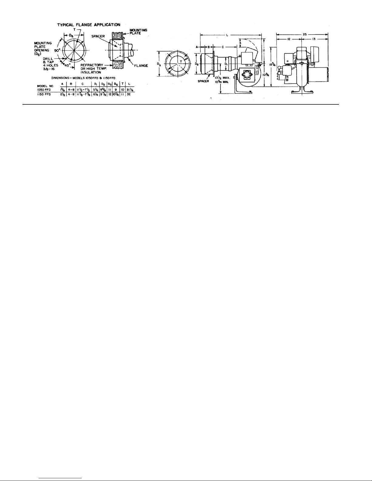
according to the dimensions shown at the top of the
previous page. (See Typical Flange Application.)
3. The diameter of the opening in the refractory or front
insulating block should equal the diameter of the opening
in the mounting plate.
4. Dimension “B”, the length of the stainless steel spacer,
should be approximately equal to the distance from the
outside of the front plate to the inside of the insulation or
refractory. See Fig. 1. When the above requirements are
met, proceed as follows:
a. Insert end of burner into opening and fasten flange
to mounting plate using four 3/8-16 x 3/4 cap
screws provided.
b. The burner mounting flange is designed to support
the burner by itself. The pedestal is furnished for
ease of installation and service where the burner is
close to the floor, also for additional support when
the mounting plate is not sufficiently strong. For the
latter purpose, blocks or bricks may be used, or a
steel shelf or the like may be fabricated and fastened to the boiler front or to the floor to support the
pedestal.
c. Make sure burner is approximately level or, if delib-
erately pitched down for a low crown sheet, that the
angle is correct.
If a system is being converted from heavy oil, the oil storage
tank must be clean. Install properly sized copper oil lines
all the way to the tank if possible. If not, replace as much of
the old piping as possible with copper lines. Also replace
old filters and fire-protective valves with new ones properly
sized.
VALVES AND FILTERS: Domestic-type fire-protective
valves, check valves, and oil filters are too small and too
restrictive for the 40 gph pumping rate of the fuel unit. Use
fittings which are equal or greater in size than the oil line on
both suction and return.
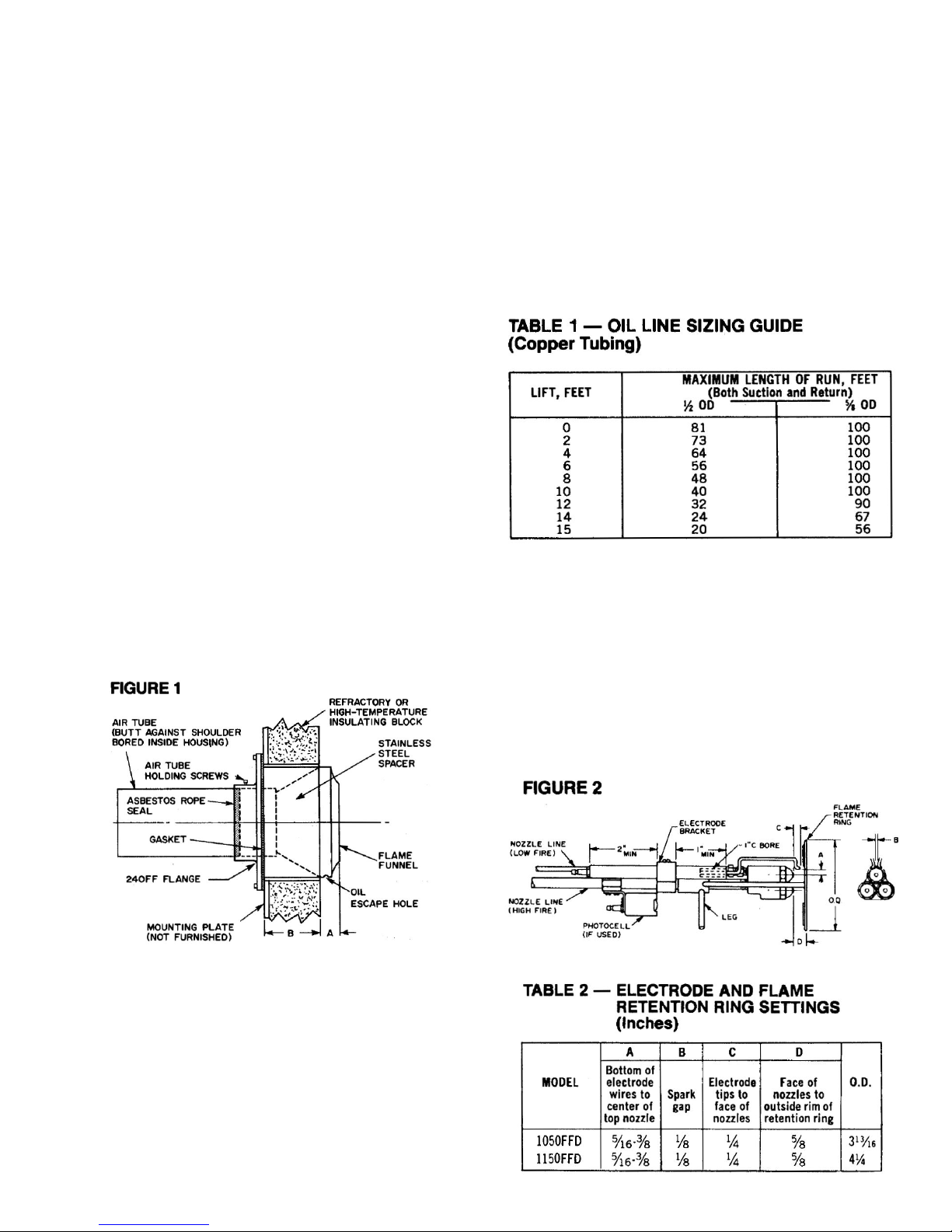
OIL LINE SIZES: Table 1 shows the OD of the copper tubing recommended, depending upon the lift and the length
of run.
NOTES
1. If lift exceeds 15 feet or if the length of run exceeds the
above, use a booster pump and system.
2. Sizes shown apply to both suction and return line for a
two-pipe system for one burner only.
3. For a multiple burner installation, use a separate suction
line for each burner. If a common return is used, it must
be increased by one size for each additional burner.
4. For one-pipe (gravity or no-lift) installations, use 1/2-inch
OD tubing for runs up to 94 feet long, and 5/8-inch OD
for runs of 95 to 150 feet long.
Oil Supply Piping
GENERAL: In systems where the bottom of the tank is
higher than, or about equal to, the level of the fuel unit, a
one-pipe system may be used. In systems requiring lift, a
two-pipe installation is required. It is essential that all air
leaks be eliminated before starting the burner. Overhead
systems should be avoided. In no case should the top of
the tank be more than 12 feet above the fuel unit. Flexible
copper tubing with flared end-fittings is strongly recommended.
32961 110916 3
 Loading...