


Component Testing
Carlin Combustion Technology, Inc.
70 Maple Street
East Longmeadow, MA 01028
Tech Service Hotline: 1-800-989-2275
Carlin Ignitor Testing Procedure
This test procedure consists of three tests. The first test should be
the ignitor spark test. The second test is a secondary coil resistance
test. The third test consists of an input current test. The following is a
step by step procedure to perform these tests. It is important that all
three of these tests be performed.
41000 Ignitor Spark Test
1. Turn off the power to the burner/appliance.
2. Disconnect the ignitor wires in the burner junction box.
3. Release the ignitor hold down screws or clips.
4. Swing the ignitor plate fully open.
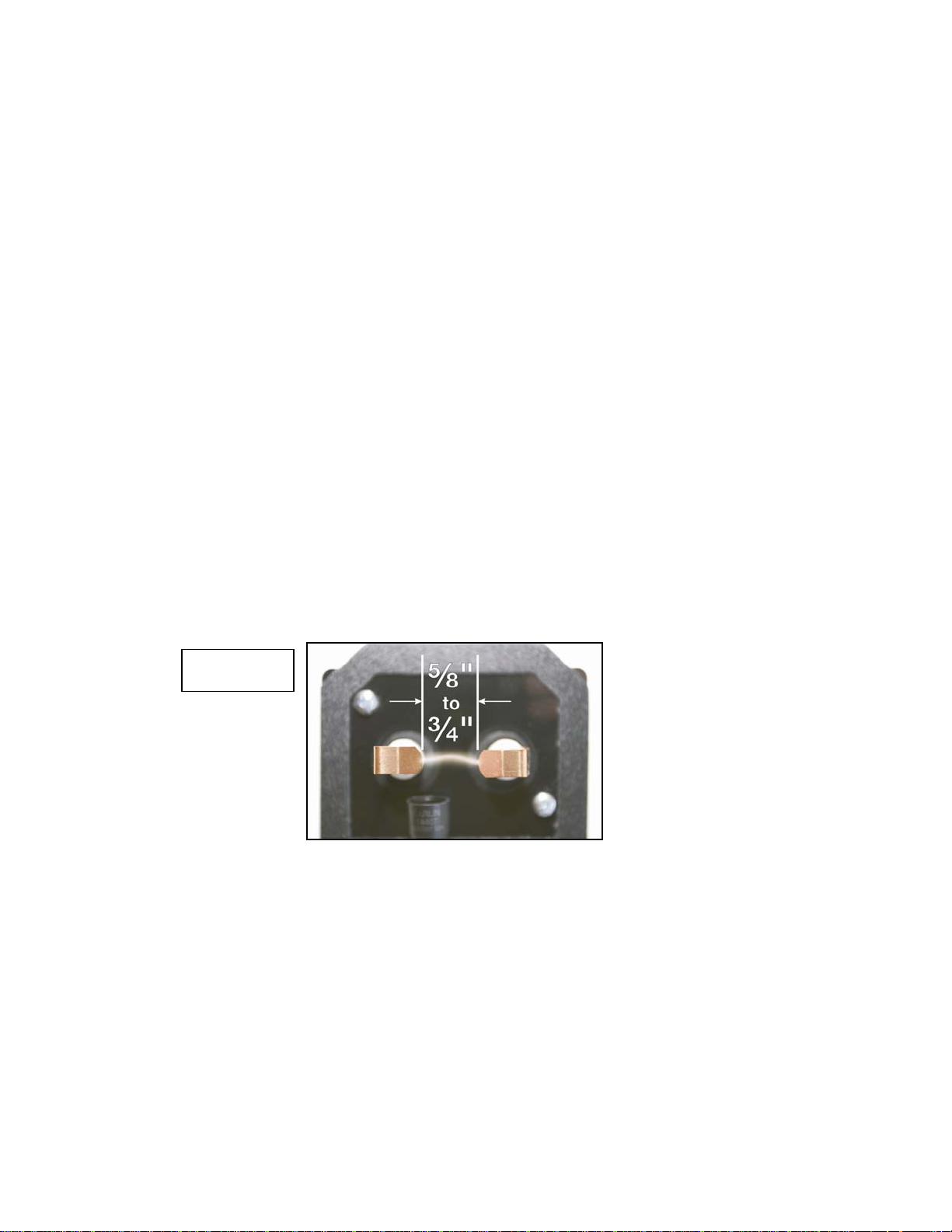
5. Bend the copper ignitor clips until the clip ends are from 5/8” to ¾” apart (see
figure 1).
6. Connect a test power cord with a switch to the ignitor leads in the burner
junction box.
7. Turn on the test power cord switch to power the ignitor.
8. Check for spark across the ignitor clip ends (see Figure 1).
9. If spark occurs, proceed the secondary coil test below.
10. If spark does not jump the gap, or if the spark jumps intermittently, ignitor is
defective and should be replaced.
11. Turn off power to the ignitor.
Figure 1
41000 Secondary Coil Resistance Test
1. Turn off the power to the burner/appliance.
2. Release the ignitor plate hold down screws or clips.
3. Swing the ignitor plate fully open.
4. Use an ohmmeter to check the resistance from electrode to ground for each of
the electrodes (Figure 2 and 3).
5. The secondary coils are good if the difference between the two readings is less
than 10%.
6. If the difference in the electrode-to-ground resistance is more than 10%, the
secondary coil may be failing. Replace the ignitor.
7. If the difference between electrode-to-ground is within 10%, proceed with the
input current test.
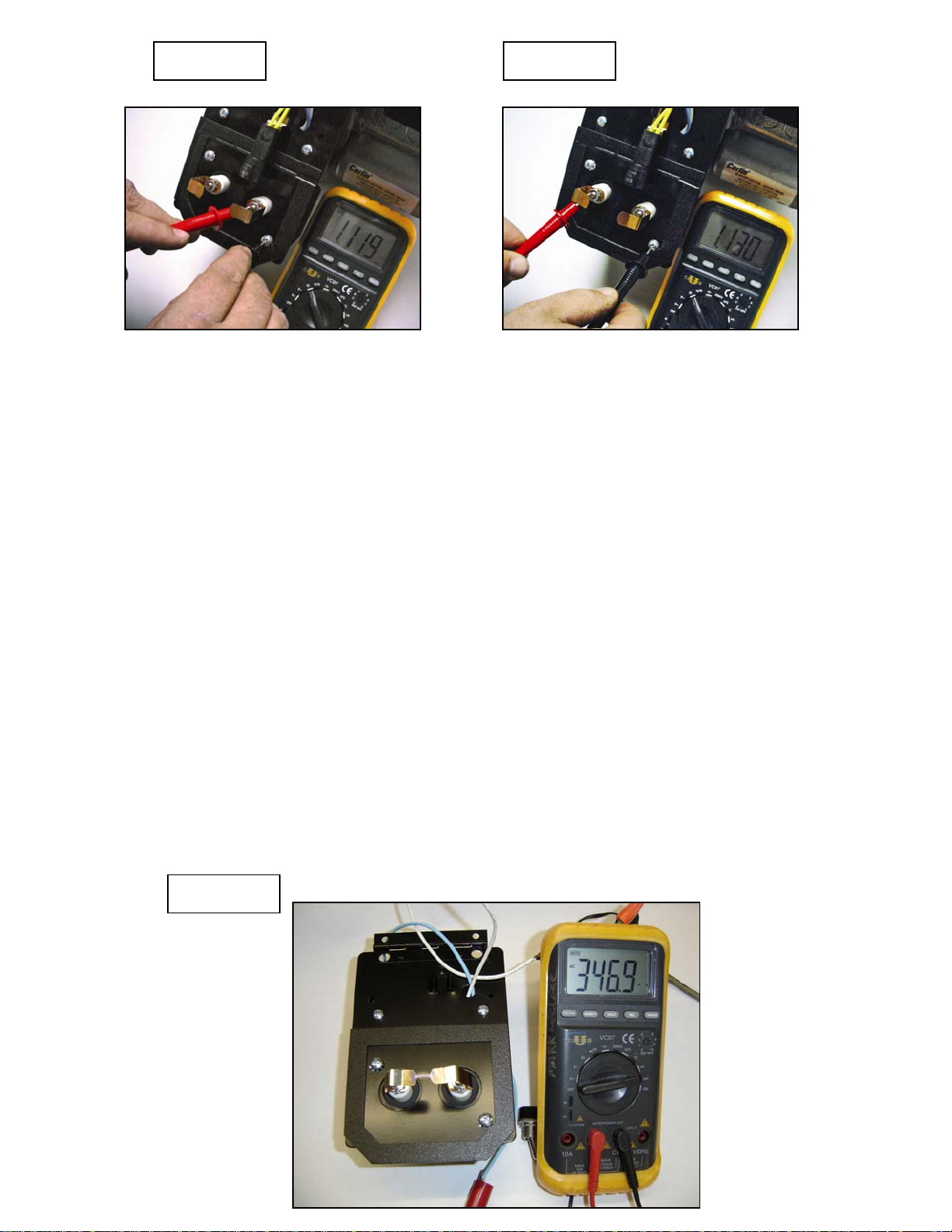
Figure 2 Figure 3
41000 Input Current Test
1. Turn off the power to the burner/appliance.
2. Disconnect the ignitor wires in the burner junction box.
3. Release the ignitor hold down screws or clips.
4. Swing the ignitor plate fully open.
5. Bend the copper ignitor clips or springs until the clip ends are ½” apart.
6. Set a multimeter to read AC milliamps.
7. Using a test power cord with a switch, wire the ignitor blue lead to one of the
multimeter leads. Wire the other lead of the multimeter to the hot side of the
test cord. Wire the white ignitor wire to the neutral side of the test cord.
(Figure 4)
8. Insure the multimeter is set for AC milliamps and turn on the test power cord
switch to power the ignitor. If there is no spark, replace the ignitor.
9. Monitor the input current with the multimeter set on AC milliamps for 5
minutes.
10. If at any time the reading drops below 300 milliamps AC, the ignitor should be
replaced.
11. Turn off the power to the ignitor.
12. Remove the power test cord.
13. Readjust ignitor clip spacing (1 inch ± 1/8 inch).
14. Wire the ignitor in its original condition (per burner wiring diagram).
15. Replace all components to normal condition.
Figure 4
Oil
Carlin U – Residential Oil Burners – Page 70
coil is normal by measuring the resis-
tance across the coil.
between the
bottom two
Valves
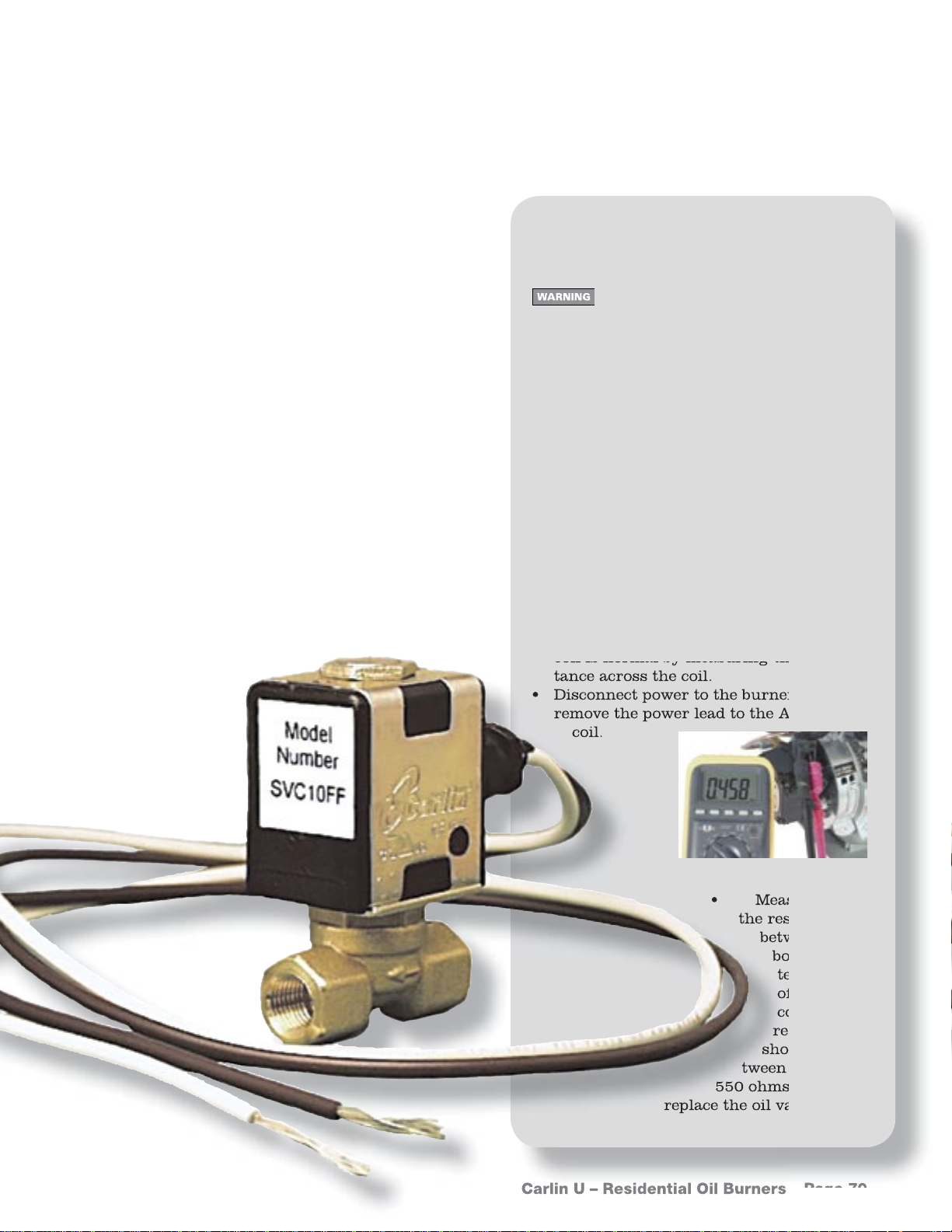
Carlin SVC-10FF
Application tips
1. Carlin solenoid oil safety shut-off
valves help to provide years of safe,
effi cient oil burner performance
while adding reliability to the burner
and oil delivery system.
2. Carlin’s SVC oil valves are direct-acting, two-way, normally-closed. Use
on single or two-pipe oil systems to
isolate the fuel pump, preventing the
possibility of oil tank siphoning.
3. Carefully review the burner instruction manual when applying to ensure the oil valve is correctly wired
and the burner fuel lines are correctly installed.
Field testing oil valves
Always disconnect power source
before wiring to avoid electrical
shock or damage to electrical components.
Checking SVC-10FF coil resistance
• You can determine whether the oil valve
coil is normal by measuring the resistance across the coil.
• Disconnect power to the burner. Then
disconnect one of the oil valve wires in
the junction box.
• Measure the resistance from one coil
wire to the other. If the coil is good, the
resistance should be between 494 and
526 ohms. If not, replace the oil valve.
Check A2VA-3006 oil valve coil resistance
• You can determine whether the oil valve
coil is normal by measuring the resistance across the coil.
• Disconnect power to the burner. Then
remove the power lead to the A2VA-3006
coil.
• Measure
the resistance
between the
bottom two
terminals
of the
coil. The
resistance
should be be-
tween 350 and
550 ohms. If not,
replace the oil valve.
Carlin U – Residential Oil Burners – Page 70

Nozzle line heater
Field testing
Advantages
• Heating the oil reduces viscosity.
Nozzle line heaters
• You can check the
integrity of a nozzle
line heater using your
Carlin multimeter.
• Disconnect power to
the burner and appliance. Make sure the
burner and all internal
parts are cool to the
touch.
• Separate the nozzle line
heater at its disconnet.
• Insert the probes of
your multimeter into
the nozzle line heater
connector sockets.
• Set the meter for ohms
and read the resistance.
• The heater is acceptable if the resistance is
between 600 ohms and
1,500 ohms.
• Start-ups are cleaner
with heated oil.
Carlin U – Residential Oil Burners – Page 75
• Replace the heater if
the resistance is less
than 600 ohms or more
than 1,500 ohms.

Cad
resistor to the other “F-F” terminal.
Cells
Cad cell construction
A cad cell contains:
• a sensing plate coated with cadmium
sulfi de.
• a metal grid on the cadmium sulfi de
to supply the two connections from
the sensor.
• a clear coating over the cadmium
sulfi de and grid that prevents contamination from moisture, dirt and
oil.
• a housing to mount the sensor assembly.
What does cadmium sulfi de do?
• Cadmium sulfi de is an electrical conductor.
• When cadmium sulfi de is exposed to
visible light, its resistance changes. The
stronger the light source, the lower the
resistance.
• When the burner isn’t fi ring, with the
cad cell inside and not exposed to any
light, the cad cell has a high resistance
(over 50,000 ohms).
• When the burner fl ame starts, the cad
cell sees the light from the fl ame, and its
resistance drops.
• The primary control (48245, 60200, for
examples) knows fl ame is present because it senses this resistance change.
Fixed resistance primary test
Use this method to test the performance of
a primary control, removing the cad
cell as a factor.
• Remove the cad cell wires
from the primary control’s
“F-F” terminals.
• Connect one end of a
¼-watt, 1500 ohm (1.5 kΩ)
resistor to one of the “F-F”
terminals.
• Start the burner. AFTER
fl ame has been established,
connect the other end of the 1.5
kΩ resistor to the other “F-F” terminal.
• If the primary control is operating correctly, it should accept this resistance
and operate normally. If the control does
not operate correctly, replace the control.
• Remove the resistor and replace the cad
cel leads on the “F-F” terminals.
Carlin U – Residential Oil Burners – Page 78

Field testing a cad cell
Light resistance:
Check room light resistance
1. With normal room lighting, the cad cell
resistance when in the open, as at right,
should be less than 10 kohms.
2. In the example shown, the resistance
measured 195.1 ohms. Notice that the
meter automatically adjusts the range
for the best reading. In this case, the
range shifted to ohms.
3. If the cad cell resistance is too high, try
cleaning the cell and measure the resistance again. If resistance is still too
high, replace the cell.
4. If the cad cell resistance is below 10
kohms, perform a dark resistance test.
Check dark resistance
1. With the cad cell mounted inside the
burner, with no fl ame, the cad cell
should have very little light available.
The cad cell resistance should be at least
50 kohms.
Cad cell resistance in
room light
Dark resistance:
Cad cell resistance
with no light (or when
inside burner with no
fl ame)
2. The illustration on bottom right shows
a test of dark resistance by securely
covering the end of the cell. In this instance, the cad cell resistance measured
82.2 kohms. (The meter automatically
changed the range to kilohms.)
3. If the cad cell resistance is below 50
kohms when the cad cell is mounted inside a closed burner with no fl ame, make
sure the combustion chamber is cool
and there is no stray light entering the
burner.
Carlin U – Residential Oil Burners – Page 79

Combustion air temp
Air changes with temperature
Recommended combustion settings
based on inlet air temperature (for locations
operating with outside air temperature between -20°F and
+90°F)
As air temperature changes, so does
the CO2 and O
• Once an oil burner is setup, the fan always
pulls through about the same volume of air
(cfm) regardless of air temperature. (Air
fl ow will be reduced if the overfi re pressure
increases due to a dirty heat exchanger,
or if the inlet air is blocked or the blower
blades are dirty or linted.)
• Air density changes with temperature. The
colder the air, the more dense the air.
• The blower pulls in a constant volume of
air. If the air density changes, weight of
air (pounds) entering the burner changes.
When the air is colder (heavier), more
pounds of air enter. When the air is warmer (lighter), less pounds of air enter.
• When combustion air comes from inside,
it comes in at room temperature, so the
temperature of the air doesn't change
much throughout the year. But when air is
ducted directly from outside, it isn't heated
much before it reaches the burner. It comes
in pretty close to the outside temperature.
In the summer, it could come in at 90°F or
higher, while coming in at below -20°F in
the winter. The air temperature difference
between summer and winter could easily be
100°F for some areas.
• The table at left shows the change in the
amount of air (pounds) as the temperature
of the air changes.
• Take the air temperature into account
when you set up a burner with ducted combustion air.
2
Carlin U – Residential Oil Burners – Page 25
• % CO2 rises as air temperature rises.
• % CO2 drops as air temperature drops.
If you don't consider this, burner combustion can become very poor as air temperature changes.
• Refer to the setup temperature chart at left
for suggested setup values based on entering air temperature.
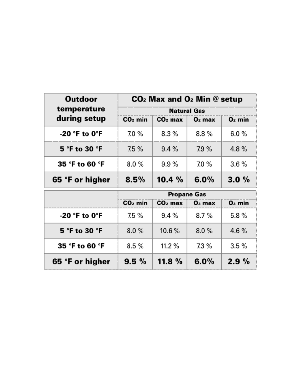
Combustion Air Temperature Chart

Thermistor Resistance
– EZ-Temp Sensors
Carlin U – Residential Oil Burners – Page 130

Thermistor Resistance
– EZ-Temp Sensors
Carlin U – Residential Oil Burners – Page 131
 Loading...